Generate an analog voltage with amplitude variations
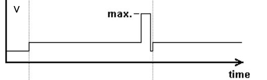
I want to generate a 0 - 5V analog voltage output that has a variable amplitude, as shown in the figure. The maximum voltage is 5V and low voltage a percentage of this, but I must not vary the amplitude during execution of VI.
With digital outputs, you are limited to two levels. Low and High. (1 and 0). Here are the outputs of the DIO lines as DC voltage levels. The two levels can be anything, but 0v is most commonly used for bass and 5v is used for the great. This is called (as well as some other features) TTL logic.
There are some cards that allow you to choose the digital voltage levels, but your all-in-one does not provide this functionality.
You could do something similar with digital, where you have only used the 0v and 5v levels.
You are absolutely right that software control timing is less precise than the timing control material, however, if you did a spot of digital output in this way and set it up to do the finished samples or continuous, it would use a material timing and would therefore be very accurate (in accordance with the specifications in the technical data of the device).
Tags: NI Hardware
Similar Questions
-
Helps with 7852R input analog voltage measurement
Hello
I'm trying to measure three signals of tension off a QPD, the three signals are connected to the IA the SCB - 68 and then I used the example of vi to acquire analog inputs with FPGA R in the finder of the example. However, I make a range of very large numbers. I don't know how to convert these volts or what are these numbers, units... etc.
Any help with this, please?
Thank you
Hi Biochemist_MU
Please take a look at the forum post FPGA of analog input and output scale. It deals with the scaling of the R-series cards.
Hope this helps and let us know if you have any other questions.
-
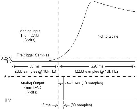
I am working with a combustion chamber and using a system of data acquisition (with the hardware OR SCB - 68) to read the pressure in the cylinder (such as analog voltage). I'm trying a pulse delayed, 1 millisecond to 5 volts of output once the pressure in the cylinder is high above 5 bar (which corresponds to an analogue voltage of 0.25 V). I would also like to record 30 ms samples before the trigger and 220 ms samples after the outbreak. The following image shows visually what I'm talking about.
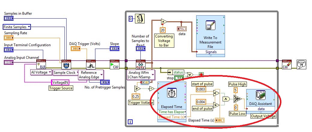
I created a LabVIEW VI (which is attached), but I keep running into 2 issues:
- When I run with samples finished after a period of time, I get error-200281which I don't quite understand.
- Using the Express VI 'Out of time' to keep time for the pulse I can not get a resolution of 1 millisecond, the pulse is not generated when I put the window between 0.003 and 0.004 seconds for high pulse (i.e. the resolution of 'Elapsed Time' seems to be too coarse).
I'm a beginner to LabVIEW sorry if my questions are trivial or my VI makes no sense, but I was stuck on this during more than a week. Any help would be greatly appreciated!
Thank you
Morgen
This isn't a good way to trigger a pulse.
Use a trigger DAQmx to send the pulse when your acquired signal exceeds 250 mV you specified.See this for DAQmx trigger:
-
faster identified measurement of AC voltage with hp34401a
Hello
I use the hp33120a to generate the signal sine with frequencysweep record und AC voltage measured with hp34401a. This measure however I consider taking unusually long for what it is(approx_3_seconds_per_measurement).here I have my postal code, if someone can give me some ideas how speed up these readings that would be appreciated.
I have
Thank you
Note: Labview 2009 SP1
You don't have to be reset and the resources of your VISA for every measurement of closing. You initialize the equipment once before the main loop, close them once after the main loop and do your reading inside the loop. This will reduce a large number of air communications that you do not want.
-
Get the duty cycle of DAQ to analog voltage input module
Hello.
I'm new to labview. I have an analog voltage input data acquisition module. I try to get the duty cycle of a square (generated from a function generator). What is the best way to go about this? When I use the vi to acquire an analog wave cyclical report, the values are incorrect.
Post your VI as well as real data of your signals so we can see what is happening.
Lynn
-
is it ok to connect two outputs analog voltage in series?
Ok... I have a PS-210 FieldPoint... basically an analog voltage output 0 - 10V, 200mA per channel (with additional external power supply)... my question is... can I plug two channels in series? Love how I can put two AA batteries in the series... and then to double my blood pressure? and then check my two separate channels and the sum of the tensions would be assujettirait I have my load in?
Thank you!
No, you can't. The channels all share the common side of their outputs. If you've tried to hang them in the series, you have wind of short-circuit one output from the ground.
The reason for which you can do with batteries is that the tensions are floating. There is no common reference between the negative terminals of both batteries.
-
Trigger SW analog voltage CONT Acq & graphic
Hello
In the example Cont Acq & chart analog voltage SW Trigger.vi It seems to me that if specify you a channel that relaxation comes on, then it would be a hardware trigger is not a software trigger. Why do call it a software trigger work?
I PCI6071E I want to trigger by sending in a channel if a pulse (63). Wouldn't that considered triggering material? If that is an example for this available?
Also I'm not clear on what they mean by the parameter ' Amplitude/hysteresis window' in the trip parameters. Could someone explain this to me?
Thank you!
-
Sampling motion controller analog voltage (from a load cell)
Dear nstroud,
Or the other of these commissions should work for you. You can configure one of the axes for engines step by step closed loop analog feedback and then put in place the other 2 axes as slaves to the first with a debt ratio of 1 to 1. This would cause all 3 of your axes to behave in the exact same way. This transmission is made on the card, and you should not see any negative impact on the axes update rates. The specified sampling rate should not be a problem either. The update of control loop period is definable in the adjustment of the loop tab, and for stepper motor axes, it determines how ofter the step generator is updated. The default for this value is 250 milliseconds. The 7340 user manual also lists the scanning speed of demultiplexer of analog input @ channel 25 microseconds / activated.
So you would be actually sampling and update the engine generator step much faster than 100 Hz with analog feedback on axis controllers.
See this knowledge base for more information about the configuration:
Analog feedback with a stepper motor:
http://digital.NI.com/public.nsf/allkb/AB3CCA7FBFAD749A8625713B001D8581?OpenDocumentBest regards
~ Nate
-
Generate the analog waveform based on the data file
I want to create an analog voltage output that follows I have a data file (excel, csv, text (which is easy)). The data file creates a waveform with equal time between steps (dT =.0034 sec). After the output through all the data points, I want it repeat indefinitely.
What is the best way to create the waveform of a data file?
To create a type of waveform data, calculate the dt by subtracting two values in column 1 and get the array of Y from column 2. If you save the file as a comma separated or tab text file, you can then use the spreadsheet file read. After obtaining a 2D array, you would use the index table and the subset of table functions.
Assuming you use a capture card data OR for the output signal, you can pass a type of waveform data to a writing DAQmx and set for the generation of types.
-
How can I connect an Apple TV to an analog TV with 2 RCA Sockets?
I have an analog TV with 2 jacks RCA - one for audio and one for video. Can I connect to an Apple TV box? Thank you.
Maybe you should try to buy this part, just connect the red plug if your TV does not have one. Here is the link: B01F77KXC0/ref = sr_1_3 https://www.amazon.com/VAlinks-Composite-Transmitter-CONVERSION-Transmission/dp/? ie = UTF8 & qid = 146898...
-
I use the outgoing/incoming analog DDK with the DAQ 6341 SMU map.
The examples, for example aoex5, show a single timer (method outTimerHelper::loadUI), but the example shows the DMA loaded with same size of vector data.
There is a comment in the outTimerHelper:
 call rogramUpdateCount, which implies that memory sizes different pad per channel can be used.
(the comment is: switching between the sizes of the various buffers is not used)
Nobody knows what should be the format the DMA buffer for data from multiple channels with different frequencies?
For example, we want a0 with a sinusoid at 1 kHz and a1 with a sine wave of 1.5 Khz. What looks like the DMA buffer?
With the same frequency for each channel, the data are interleaved, for example (ao0 #0, ao1 #0; ao0 ao1 #1, #1,...), but when the frequencies for each channel is different, what the stamp looks like?
Hello Kenstern,
Data are always intertwined since each card has only a single timing for each subsystem engine.
To AO, you must specify the number of samples that will be released to the AO. You also specify the number of channels. Because he didn't is that a single engine timing for AO, each AO will be channel will be updated at the same time to update clock tick. Data will be interlaced exactly as shown in the example because each channel AO needs output at each tick of the clock to update. The data itself can change depending on the frequency you want to copy.
kenstern wrote:
For example, we want a0 with a sinusoid at 1 kHz and a1 with a sine wave of 1.5 Khz. What looks like the DMA buffer?
With the same frequency for each channel, the data are interleaved, for example (ao0 #0, ao1 #0; ao0 ao1 #1, #1,...), but when the frequencies for each channel is different, what the stamp looks like?
In your example, you must come with an update rate that works for the two waveforms (sine waves of 1 and 1.5 KHz). To get a good representation of a sine wave, you need to update more than 10 x faster than your fastest frequency... I would recommend x 100 if possible.
Update frequency: 150 KHz
Channels: 2
Then create you stamps that include complete cycles of each wave you want to produce based on the frequency of update. These buffers must also be of the same size.
Buffer 1: Contains data for the sine wave of 1 KHz, 300 points 2 cycles of sine wave
Buffer 2: Contains data for the sine wave of 1.5 KHz, 300 points, 3 cycles of sine wave
You can Interleave them as before. When the data are performed through the ADC, they are out different sine waves, even if the AO channels are updated at the same speed.
-
PCI 6221 generating an output voltage
Hi all
I'm trying to use a card PCI-6221 to provide a voltage of 5V analogue output and use it HAVE read the returned signal using labview. Anyone know how I can do this using this hardware device?
Thank you
Hi lrving9,
First you need the DAQmx driver, here is the link for you to install the latest version.
NOR-DAQmx 15.0.1
http://www.NI.com/download/NI-DAQmx-15.0.1/5353/en/If you already have it, so go ahead and take a look at this example:
It shows you how an analog DC output voltage.
Community: Output analog voltage constant
https://decibel.NI.com/content/docs/doc-18631So you have a block of connection to connect the signals?
If you do, then you can simply create a task to read a continuous voltage entry, as in this example
Community: - Input voltage
https://decibel.NI.com/content/docs/doc-25105If you do not have a connection block and have no way to connect the OD to HAVE, then you can read the inner channel of AO, as shown in this link (there is an example at the bottom):
It is Possible to read the value of the digital or analog output channels?
http://digital.NI.com/public.nsf/allkb/CB86B3B174763C3E86256FFD007A2511Also when you install the driver a few examples are installed as well, this shows you how to get them:
Where are the examples of NOR-DAQmx installed?
http://digital.NI.com/public.nsf/allkb/E3BAF6FC4017960B8625755A00525D37Kind regards
Caroline
-
Hello
How acquire and store the values of voltage DAQmx?
I tried several code example, but they can't get the chart. I don't want to chart. I want to measure exactly the analog voltage values and record these values - as an excel chart, that contains the selected channels and voltage values.
What the example code that I can use?
My hardware is NI PCI-6251.
Thank you very much.
-
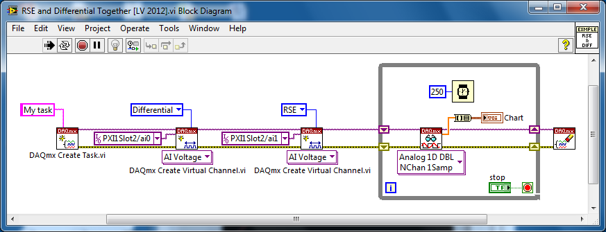
Several analog inputs with different configuration differential/CSR
Hello
Can anyone tell how to measure two analog inputs with different configurations using a USB-6009?
I am aware of the syntax for create virtual channels for the channels DAQmx create virtual so I created two strings using Dev3 / ai0:1 but I would like the first string of the CSR and the second to be differential.
So far I have found no way to specify the configuration of the separate channels.Any ideas much appreciated!
Jack
JackT wrote:
I prefer to use the 'low' level vi is therefore always curious to know if there is a way to set the configuration using the their.
It should be like this:
-
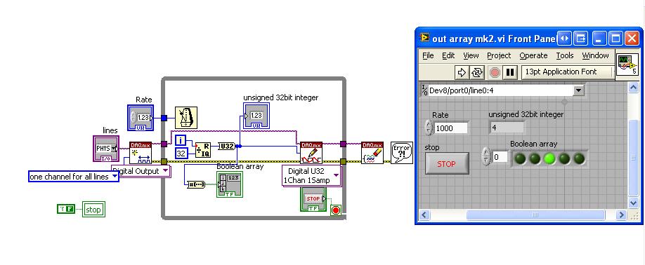
Generate a binary sequence with the NI USB-6008
Hi all
I'm new to LabView and I am trying to generate a binary sequence with a box NI USB-6008. The sequence, I'm currently generate is a counter of 5 bits, i.e. 00000 00001 00010, 00011... 11110, 11111 placing each bit in a different digital IO of the of the 6008 NOR, so that I can use the County as the bits of selection in a decoder/demux.
I managed to simulate the binary sequence and produce a graphical interface, but I have not found how to generate the sequence of bits with the NI 6008.
Totally, I'd appreciate any help you could provide. Thank you very much.
Hi JosephM,
Good Afternooon and I hope your well today.
I just tested the code on a 6008 and also released the above code is very complex - I was for some reason any fixed on using Boolean tables.
Please see the attached code, in LabVIEW 8.6.
Mind you, I have configured the task as a channel for all lines. i.e. digital single I spent, is the task value should apply to all channels selected in the entry. So if you select only port0/Dev8/$line0 for example, the DAQmx driver will examine the LSB of the digital and work so $line0 must be true from the false. It will NOT update all other channels. So when I select line0:4 - it will update the first 5 lines (bits) in digital. As the code generates a number from 0-32 he emotional generates 00000 to 11111.
I hope this finds you well and sorry for the first post!
Maybe you are looking for
-
I have 8 GB iphone4 I want to be updated with iOS 8
provide my with iOS 8
-
Satellite 5105-s701: one or two red vertical lines on LCD
My 5105-s701 suddenly started showing a line or two red vertically (top to bottom) of the screen. They appear as I change the angle of the screen and sometimes stay after the removal of the display. I can get rid of them by moving the screen several
-
L450 blocked to 0.77 GHz processor when it is on battery and can not downgrade the BIOS
Hello It seems that the CPU of my L450 is blocked to 0.77 GHz speed when it is running on battery power and no matter how heavy the load, the CPU speed does not fit on the rise, unless I plug in the AC power cord. This makes the laptop a bit useless
-
HP Deskjet F380 analysis does not correctly.
Original title: Device HP Deskjet F380 Hello When I scan a document, only 30% to 50% of the document is scanned. I don't know why. If I rescan it it can scan a whole page or can choose another 60% of the document and leave the rest in white.
-
Acer 1640Z crashed XP to restore aid.
Laptop spare as above Windows XP. Three days ago, I configured the Acer e parameters and inadvertently pressed a wrong button. He began to wipe everything. I turned off after 6-7 seconds, and restarting the laptop wouldn't start. 1 message: NTLDR is