Sampling motion controller analog voltage (from a load cell)
Dear nstroud,
Or the other of these commissions should work for you. You can configure one of the axes for engines step by step closed loop analog feedback and then put in place the other 2 axes as slaves to the first with a debt ratio of 1 to 1. This would cause all 3 of your axes to behave in the exact same way. This transmission is made on the card, and you should not see any negative impact on the axes update rates. The specified sampling rate should not be a problem either. The update of control loop period is definable in the adjustment of the loop tab, and for stepper motor axes, it determines how ofter the step generator is updated. The default for this value is 250 milliseconds. The 7340 user manual also lists the scanning speed of demultiplexer of analog input @ channel 25 microseconds / activated.
So you would be actually sampling and update the engine generator step much faster than 100 Hz with analog feedback on axis controllers.
See this knowledge base for more information about the configuration:
Analog feedback with a stepper motor:
http://digital.NI.com/public.nsf/allkb/AB3CCA7FBFAD749A8625713B001D8581?OpenDocument
Best regards
~ Nate
Tags: NI Hardware
Similar Questions
-
Configure a load cell connected to multifunction DAQ
I'm trying to connect a LCDH Omega 10 K scale by a module of constraint Dataforth SCM5B38-37 then AI0 gauge on a USB-6251 multifunction data acquisition.
In addition to the load cell, the application will use a pressure sensor with a strain gauge bridge module plugged into AI1 to read the pressure of hydrulic. The pressure transducer using a measure of the force will be calculated and compared with the reading of load cell.
Currently, the USB-6251 box is configured to read analog voltage on AI0. The scale is then performed using linear Fit.VI.
Review the example Bridge - entry continues shows some additional controls may increase the accuracy of the reading.
Unfortunately trying to use the DAQ Assistant only added to my confusion of the best practice in the acquisition of a signal from a load cell.
__________________________________________________________
Here are some of the questions I have...
What is the best practice implement a load cell using a full bridge strain gauge conditioning module labview?
What is shunt calibration? Is this similar to the USB-9237 DAQ modules-specific?
How do you know if your sensor is set up like a full bridge, half bridge, etc, the document load cell does not it?
You can use the VI delete DAQmx perform bridge?
_________________________________________________________________
I don't know, I understand all the information of the map calibration either.
Why is there resistance to entry and exit values?
What is the value of the zero balance signafiance?
Specifications of load cell
Lbs mV/V
0.000 0
2000 0.598
4000 1,201
6000 1,804
8000 2,404
10000 3.002
Excitement: 10 VDC
Input resistance: 350,41 Ohms
Output resistance: 352,08 Ohms
Balance zero: 0.01 mV/V
Hello!
I was looking into your question and found a few links that might help you configure your system. The first is a white paper that discusses some of the basic concepts of the gauges of constraint and their use with LabVIEW, shunt calibration and also covers some of the resistance values you see:
http://www.NI.com/white-paper/3642/en/
As you can see in this article, we have some specific hardware, built for the kind of measures you take. Because these devices are manufactured specifically for this application, they would provide better and more reliable results. That being said, you can configure your system with your USB-6521, it might not be as accurate as one of these systems. To set up your measurement system, rather than defining the analog input as a measure of deformation, you want to use the voltage custom with the option of excitement. This article treats this yet:
http://digital.NI.com/public.nsf/allkb/C66F92BDE229F45A86257B6D004D6033
We get you your data in the form of Volts/Volts (this document addresses more info on bridge probe scaling: http://zone.ni.com/reference/en-XX/help/370466W-01/measfunds/bridgescaling/), , but you should make sure you standardize this value to the excitement. Devices such as the NI 9237 provide the voltage and can take this known value in to account within the program, but you may need to do this manually for your application. Here is additional information on the NI 9237 and how it is configured to read information from strain gauge:
http://digital.NI.com/public.nsf/allkb/892C84122A6501AE86257547007E5C53?OpenDocument
Regarding the configuration of unit load and the information, you can try to contact the manufacturer for more information!
Thank you!
-
I use an external powere supply 12V to supply voltage to the load cell, and I'm reading data using AIO-600. There is a separate module that can do this, but is it possible to do it with the current material?
Russell,
The lowest input for the AIO-600 range is 0 - 6V. This means that you will have a resolution of 12 bits (11.3 effective) broadcast more than 6 volts. I guess that your full scale signal max will be 36mV. Without amplification, you will not have a very high quality signal. It would be the best bet to amplify your output signal mV as close to the load as possible cell and then connect this signal amplified to your AIO-600.
Best,
Chris LS
-
is it ok to connect two outputs analog voltage in series?
Ok... I have a PS-210 FieldPoint... basically an analog voltage output 0 - 10V, 200mA per channel (with additional external power supply)... my question is... can I plug two channels in series? Love how I can put two AA batteries in the series... and then to double my blood pressure? and then check my two separate channels and the sum of the tensions would be assujettirait I have my load in?
Thank you!
No, you can't. The channels all share the common side of their outputs. If you've tried to hang them in the series, you have wind of short-circuit one output from the ground.
The reason for which you can do with batteries is that the tensions are floating. There is no common reference between the negative terminals of both batteries.
-
NEITHER 9234 with quasi static analog voltage
Hello
I have a NI 9234 (4 channels + / IEPE 24-bit 5V) attached to a chassis cRIO module. This module is ideal for accelerometers and microphones where the tension is in constant evolution (ie; measures of variation rates).
I also have a module OR 9237 (4 channels 24-bit full-bridge module analog input) attached to the same cRIO. This module is ideal for measure variable voltages of strain gauges (quasi static and dynamic loads).
The attached graph shows the two channels, collected synchronously, but as you can see the (red trace) cell breaks down (as it should), but then drifts back to zero on its own, when in fact it should remain low just like the extensometer is beam. After all, the two sensors are physically secured.
Q1: Would that have something to do with AC/DC module 9234 internal coupling?
Q2: Is it really possible to collect "quasi static" ongoing tensions by using a NI 9234 module?
No explanation as to why this occurs, or if there is a way to remedy this would be appreciated.
Kind regards
Andreas
Coupling AC/DC must do a lot with your question. In mode AC voltages static will be fitered outside and the 9234 measure indeed only change voltages. In DC mode, the voltage goes directly to the AD converter and you can also detect static tensions.
A minute of Googling gave me the answer, this load cell electric piezo can measure dynamic changes, as any charge will escape the path the lowest resistance and the signal will go to zero after a certain time. I guess the other device you were using higher internal resistance (which is relatively low on the 9234), so it takes more time to what he flees, but he also took on the picture you attached your second try.
Here you can find more example under the title
"WHY ONLY DYNAMIC FORCE CAN BE MEASURED WITH SENSORS OF POWER PIEZOELECTRIC"
http://www.PCB.com/techsupport/tech_force
Andreas Jost
Technical sales engineer
National Instruments
-
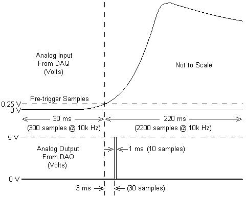
I am working with a combustion chamber and using a system of data acquisition (with the hardware OR SCB - 68) to read the pressure in the cylinder (such as analog voltage). I'm trying a pulse delayed, 1 millisecond to 5 volts of output once the pressure in the cylinder is high above 5 bar (which corresponds to an analogue voltage of 0.25 V). I would also like to record 30 ms samples before the trigger and 220 ms samples after the outbreak. The following image shows visually what I'm talking about.
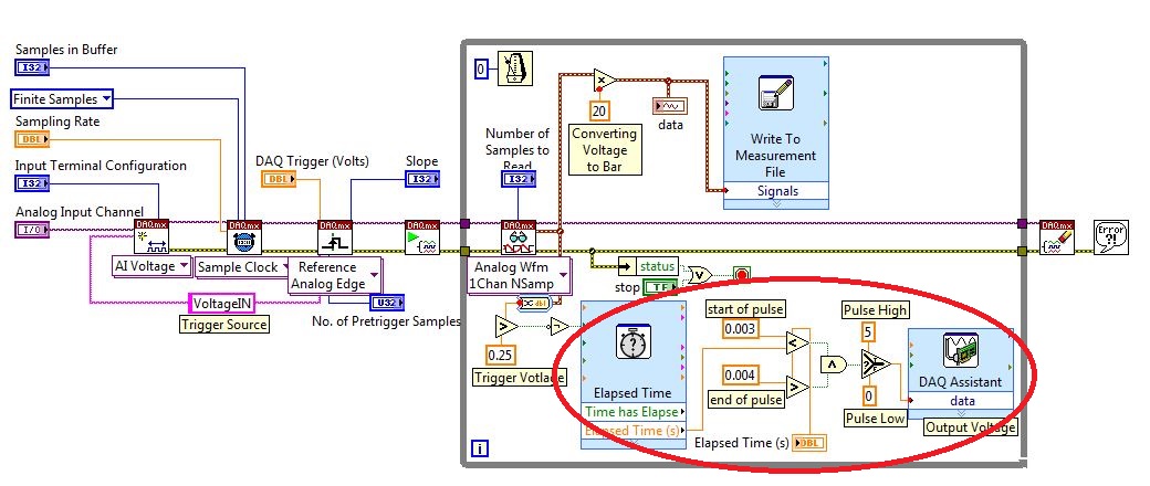
I created a LabVIEW VI (which is attached), but I keep running into 2 issues:
- When I run with samples finished after a period of time, I get error-200281which I don't quite understand.
- Using the Express VI 'Out of time' to keep time for the pulse I can not get a resolution of 1 millisecond, the pulse is not generated when I put the window between 0.003 and 0.004 seconds for high pulse (i.e. the resolution of 'Elapsed Time' seems to be too coarse).
I'm a beginner to LabVIEW sorry if my questions are trivial or my VI makes no sense, but I was stuck on this during more than a week. Any help would be greatly appreciated!
Thank you
Morgen
This isn't a good way to trigger a pulse.
Use a trigger DAQmx to send the pulse when your acquired signal exceeds 250 mV you specified.See this for DAQmx trigger:
-
Get the duty cycle of DAQ to analog voltage input module
Hello.
I'm new to labview. I have an analog voltage input data acquisition module. I try to get the duty cycle of a square (generated from a function generator). What is the best way to go about this? When I use the vi to acquire an analog wave cyclical report, the values are incorrect.
Post your VI as well as real data of your signals so we can see what is happening.
Lynn
-
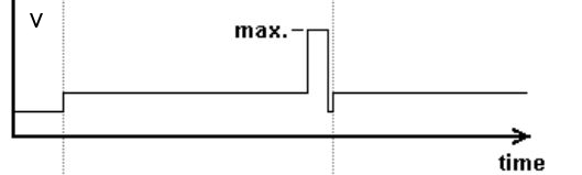
Generate an analog voltage with amplitude variations
I want to generate a 0 - 5V analog voltage output that has a variable amplitude, as shown in the figure. The maximum voltage is 5V and low voltage a percentage of this, but I must not vary the amplitude during execution of VI.
With digital outputs, you are limited to two levels. Low and High. (1 and 0). Here are the outputs of the DIO lines as DC voltage levels. The two levels can be anything, but 0v is most commonly used for bass and 5v is used for the great. This is called (as well as some other features) TTL logic.
There are some cards that allow you to choose the digital voltage levels, but your all-in-one does not provide this functionality.
You could do something similar with digital, where you have only used the 0v and 5v levels.
You are absolutely right that software control timing is less precise than the timing control material, however, if you did a spot of digital output in this way and set it up to do the finished samples or continuous, it would use a material timing and would therefore be very accurate (in accordance with the specifications in the technical data of the device).
-
CompactDAQ trigger out voltage to a load of 9237
I'm just trigger off an a charge of monitoring load cell load threshold. It seems that the 9237 has not directly this feature as some analog modules. I also need to capture one or two seconds of data pre-trigger. My programming skills are at a level CLAD and I was wondering if a: this is possible (that I thing it runs a bunch of loops) B: or if someone has tried this with any success?
Thank you
Matt
Hi Matt,
With the 9237, you will still be able to do a software analog trigger. There is a very good example here that you may find very useful. The example was built for a 9233, but you can change the task at a voltage of strain/custom with exe task depending on your 9237. I gave it a shot with a simulated device and it worked fine. Let me know if you have any other questions after reviewing that. Have a good!
-
jump motion controller is disconnected
Product name: HP ENVY 17 Leap SE NB PC Motion
8.1 Windows 64-bit
Greetings,
After a complete restore of the system 'fn + SPACEBAR' does not have the motion controller tunring jump on, I checked in the device sound Manager there, when I move the mouse in the toolbar on the controller icon I get the message "jump motion control is disconnected.
Hello
The first thing I would say (unless you already have) is to download and install the latest software to jump on the following link motion controller.
http://ftp.HP.com/pub/SoftPaq/sp67001-67500/sp67321.exe
When the installation is complete, reboot the laptop and let Windows take over completely for a few minutes before checking the fn + space combination.
Kind regards
DP - K
-
NIDAQmx to simulate synchronized analog input from two devices of simulations?
I would test synchronized analog input from two MFDs simulated from the NI6225. I created two devices of simulated able NI6225 & Automation (M & A) and tagged the first NI6225a and the second NI6225b. M & I created a RTSI cable configuration and added both simulated devices. However, when you call NIDAQmx C functions in my test code, I get an error condition indicating that the simulations devices are not synchronized. Before continuing, I would like firstly to confirm if NIDAQmx is designed to
simulate synchronized the analog input data of two devices of simulations. If this isn't the case, then it will explain the error condition that I have encountered in my test code.
Thank you
Ian
Hello John and Jared,
If I remember well used to support the simulated synchronized devices. I ran various tests this week, but all fail. I'm going to order/install a RTSI cable and test with physical devices.
Thanks for your help. I close this post.
Ian
-
Hello
How acquire and store the values of voltage DAQmx?
I tried several code example, but they can't get the chart. I don't want to chart. I want to measure exactly the analog voltage values and record these values - as an excel chart, that contains the selected channels and voltage values.
What the example code that I can use?
My hardware is NI PCI-6251.
Thank you very much.
-
Trigger SW analog voltage CONT Acq & graphic
Hello
In the example Cont Acq & chart analog voltage SW Trigger.vi It seems to me that if specify you a channel that relaxation comes on, then it would be a hardware trigger is not a software trigger. Why do call it a software trigger work?
I PCI6071E I want to trigger by sending in a channel if a pulse (63). Wouldn't that considered triggering material? If that is an example for this available?
Also I'm not clear on what they mean by the parameter ' Amplitude/hysteresis window' in the trip parameters. Could someone explain this to me?
Thank you!
-
Cannot find the motion controller
I use a 12 unidex by aerotech motion controller. My labview program worked well, my motion controller when all of a sudden he couldn't find it. I went measures and tab automation looking for him, but he could not find the controller. The program has been able to find all other connected devices, but not the command of movement. I disconnected all other devices except the unidex and labview still could not find it. Then I took the controller and it covered on an identical motion controller (no reason to). Not only labview couldn't find the first motion controller, he could yet find that I had grafted on. Thoughts?
Good new everyone: the GPIB address was surreptitously to 0 which remote impossible given that this value is reserved for the GPIB controller. I appreciate the advice of each.
-
Call or function of the class from a loaded MC
Hello
Can someone tell me if its possible to call a function or a class from a loaded MC?
mainMovie charge MC > MC calls the function in a class of mainMovie
If so, what is the best method?
I tried this loaded MC but (of course) an error:
movieClip (parent.parent). DO_THIS();
Thanks for everything 'light' on this.
Have the loaded SWF file send a custom event that spreads and listen to this event in the parent.
In SWF loaded:
dispatchEvent (new Event ("customEvent", true));
Parent:
addEventListener ("customEvent", handleCustomEvent);
function handleCustomEvent(event:Event):void
{
do your stuff in the parent here
}TS
Maybe you are looking for
-
Since the update to warchOS3, I can not do a screen shot on my Apple Watch. Anyone has any idea why?
-
Firefox does not open my website on my computer
Yesterday, I was able to open my new Wix website on firefox and Chrome, but today Firefox does not open it on my computer but it if it opens on my friend's computer. Help, please!
-
Is there a way to disable the brightness on my keyboard keys?
It's really bad if I accidentally hit my keyboard brightness keys because my monitor must be calibrated very at all times since I was a photographer. Someone knows how to turn off these keys I don't accidentally hit? Thank you!
-
Installing Win7 on Satellite A300-23d
Hello I went and got the Win7 in a store.I realized that it would be preferable to install the Windows 7 with the help of KILLED because of the Toshiba utility... when I started killed HER, he stopped and said that "this model do not support win7 upg
-
Hello I use several USB 6009 units and with some of them seems to have some lag in differential mode, I with 0 to 1V range. Grounded the two terminals with resistors as shown in the tutorial OR «wiring field and noise review...» "seems to fix the pro