generate the signal of decimal number
Hello
I have a program that calculate the heart rate from the ECG signal. I want to show the beats per minute on a graph with 60 s of the plot of the story.
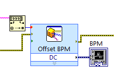
Since the vi who calculate the heartbeat I get output the string with the number, only when the wave of the tip, then I convert it to a number and then I place the offset of a simulated DC signal.
(In the table below the beats per minute are always 60 because I'm simulating a sinusoidal signal with 1 Hz).
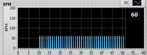
It works fine, but I'd like to see not the summits but a continuous line from one point to another, such as interpolation.
in this case, it would have been a horizontal line to 60 BPM.
I thought to store the last value of the chain and keep it frozen until the next update of value.
Do you have suggestions on how to do it?
Concerning
Not clear what you get in the form of numbers, seems that you get too many zeros, and you get a decimal number or another 'dynamic '? value?
You pulse-rate information could be ~ 45 to > 180 values per minute!
You display the exact story of a minute? Maybe (keep the last ~ 300 values with timestamps and use an XY diagram) a graphic story can be configured to display
wait... Here's one way:
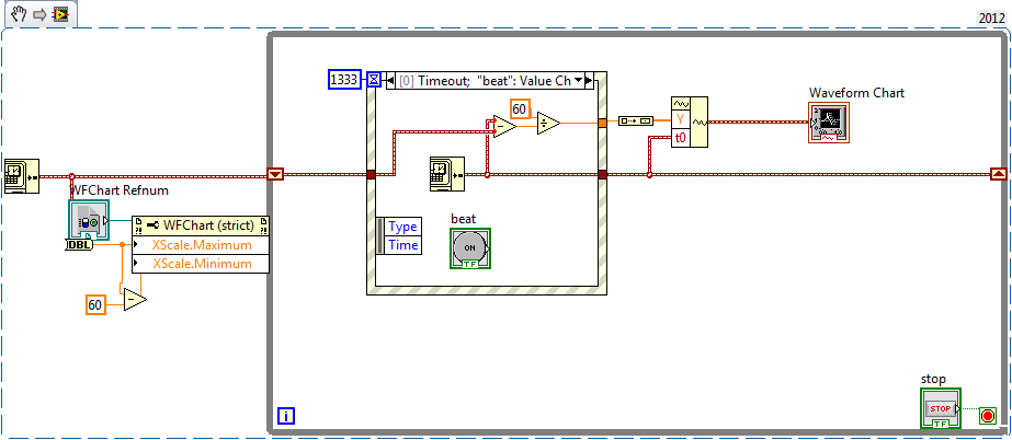
I fed a chart (with 256 points in history), with a waveform. the wfrm has only a single value in the array of values and a t0. The chart is configured to display the 60 sec. Seems to work
My simulation will display a min rate of ~ 45 BPM, but you can beat him
Tags: NI Software
Similar Questions
-
Result of the calculation were separated to the whole and decimal, number not rounding correctly
I have 2 fields as a result of sharing: the whole and decimal number (1 decimal place). I Math.floor the result to get the whole number and everything is fine until I hit a case where the result is 92,97.
This should give "93" in the whole of the field and '0' in the decimal field, instead it gives me '92' and '10' (even though I'm only hosting 1 character in the field).
How can I get the '93' and '0' in the following code?
fieldLVEDV = this.getField("LVEDV").value;
fieldBSA = this.getField("BSA").value;
If (fieldLVEDV! = "" & & fieldBSA! = "") {}
totalLVEDV = this.getField("LVEDV").value + ((this.getField("LVEDVDec").value)/10);
calculation = (totalLVEDV / fieldBSA);
calculationDecimal = calculation;
partWhole = Math.floor (calculation);
if(partWhole <0) {partWhole =' ' ;}}
this.getField("Index").value = partWhole;
this.getField("IndexDecimal").value = Math.round (10 *(calculationDecimal-partWhole));
{If (this.getField("IndexDecimal").value = '10')
{
this.getField("Index").value = partWhole + 1;
this.getField("IndexDecimal").value = "0".
}}
} else {}
this.getField("Index").value = "";
this.getField("IndexDecimal").value = "";
}
I thought I'd add the blue part would do the job, but obviously it did not work.
Ah, your problem is that you do not use the correct comparison operator. To check if two values are equal, the operator is "==" not not "=". Using "=", you assign the value 10 to the field which you then pass in 0 a few lines down. Use 'is' and things should work correctly.
-
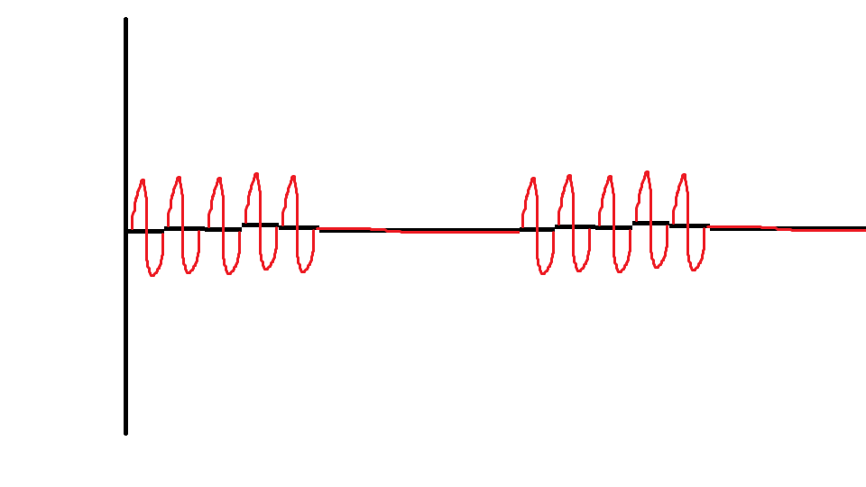
Generating the signal as shown in the picture in labview
Hello
I'm using labview in 2011 and want to generate the second signal as shown in the picture attached in labview as I want to use it as input to implement adaptive filtering, if the first signal in the image represents the output of the adaptive filtering area.
May I know how to generate a second signal.
Thank you.
-
Connection diagram missing in DAQ Assistant generate the signalling block
This is my first post so please excuse the quality of my description.
When I double click on the block of data acquisition - Assistant, there is no tab connection diagram I can access to see how things are wired to the top. I have a NI USB-6211 connected by USB and it is used to control many different sensors and a power supply. Currently, he works for everything and is hard wired correctly, but only blocks DAQ Assistant has a connection diagram available, the other are not. One who has a connection diagram is used to measure a voltage. Others who do not are used to generate a signal. I would really like to be able to see patterns of connection for each block.
-Any help would be appreciated
-Thank you
You can always do like those who never use the DAQ Assistant and read the manual. Right click on the device in MAX and selecting "stitching of the device" works too.
-
generate the signal f = 50 Hz with NOR-9264
Hello. I am Sorin.
I need to generate a sinusoidal waveform with f = 50 Hz, U is 3Vrms. I have a C, OR-9264 module. Is it good? Or can it only generates SCR?
I don't have C modules: I for RTD, V, mA, universal and AO for V and mA.
What can I use?
Thank you.
It DOES not say that it displays up to 25 kech. / s (25000 samples per second). It's more than enough for 50 hz.
-
Big latency constant to generate the signals AO which is an immediate copy of the signals HAVE.
-
Looping/cycling through frequencies with the signal to create VI
Hello
I am trying to operate a PZT with a given signal (of a formula) and to save the output of the sensors. I use a PXI of NI 5421 to generate the signal and an NI PXI 5105 to record signals. I made the attached code that works well, however, I'd like to be able to the frequency and the number of samples (the number of samples is function of frequency) in the VI of signal to create loop so that I can scan a range of frequencies. Could you please help me. I can't find a way to control the frequency outside the edit in the Properties window.
Thank you
Casey
Sanjay-thank you
I just thought of it. I Redid the vi and when I ran an error that said come the input signal must be an integer value to a multiple of 4. I made a few simple changes to make and after that everything worked as expected. I guess that the entrance of waveform looked ok but not get operated by material, unless it is a multiple of 4.
Thanks for your help,
Casey
-
Hello
We need power RF amplifier with a function generator to create plasma in an ion source. The signal pulse duration must be 1ms long, repeated twice per second.
Today, we work in the following way: we spend the RF with f0 (aprox 1,995 MHz) frequency. After 20, we send a trigger signal passing frequency f1 (aprox 2.005 MHz). We keep this frequency for the rest of the pulse. However, the plasma that we generate is not 'constant' or stable during the whole impulse. If we smoothly change the frequency during the pulse we could improve.
We would like to do: use the frequency sweep: rather than use this frequency hopping, we would like to move smoothly f0 f1 (frequency scanning). Then F1 to f2.
As we have a PXI for data analysis, we believe using the arbitrary function generator of NOR: 5406 of NEITHER allowing the frequency sweep. However, in the book loads, it is not very clear, and I have a few questions:
-We can create a "list of frequencies. In the site OR below, it shows that the "minimum of Step' is 1.28us, which would be ok for us (I understand that the"minimum duration of Step"is the minimum time between 2 frequencies). However, the manual of the device "NI PXI/PCI-5402/5406 specifications" said the frequency list has a time step of 1 ms to 21s. What is the good?
-It is also said that the "duration of minimum list" is 1 s. For us, need us a shorter list that 0.5 seconds (we need to repeat the same pulse twice per second.). Is it possible to do what we want?
-At the end of the day, we would like to implement a control loop which modifies the list of frequencies in real-time.
http://zone.NI.com/reference/en-XX/help/370524L-01/nisignal_generators_help/features_by_device_smc/
Thanks for your help.
Best regards
Jose.Hi Jose,
You're right about the inconsistencies of the documentation. The minimum step was of 1 ms, but was changed to 1.28 µs to driver version 2.6. The help document has been modified to reflect that, but the specifications were not. I'll make sure that attaches.
The length of the minimum list is not listed in the book loads, and the latest version of the help the signal generators OR (driver version 2.9) lists the minimum list than the 1 step length. Aid has changed to the driver version 2.6.1 to clarify that the 1s meant 1 step. I've attached a screenshot of the help of the most recent.
There is an example that is installed with the NOR-FGEN driver called "Fgen Sweep Generator.vi". I would recommend from this for your application.
I hope that some of the inconsistencies in our documentation brightened. Please let us know if you have any other questions.
Elizabeth K.
Generators of signal produced technical support engineer
-
Hello
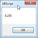
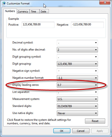
I am trying to print the decimal number, but I've always had the decimal number (between-1 to 1) witout '0' or '-0 ".
Var num:num = 0,235
MsgBox (num)
her impression: ".." 235.
Thank you
Hello OzShimon,
It's weird, I just tried your code and get this result:
I noticed that this behavior can be changed in the configuration "Regions and languages" of Windows. In Windows 7, it's this dialog box:
If I change the settings of this dialog to any of the zeros, the result is the same as you have described.
Can you check your Windows settings and confirm that yours looks the same as mine?
Best regards
Otmar
-
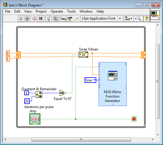
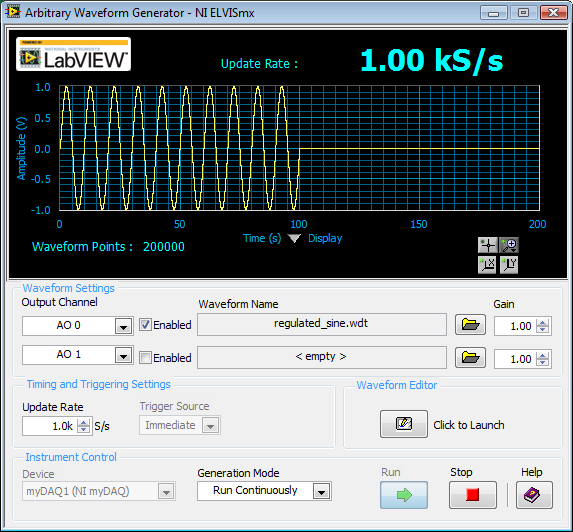
How to generate a pulse with the signal generator?
Hello
I would like to ask if anyone knows how to use the Elvis platform to generate a regulated pulse wave?
It should look roughly like the picture above. A sine wave with the regulation.
Anyone who can answer my question please respond to my post.
Thank you.
You are using LabVIEW to generate the waveform or using the Soft front panels? In LabVIEW, you can use the express VI generator function and specify the Type as "Sine". Then, simply change the amplitude of the sine wave. During the actual pulse, the amplitude would be what you want (i.e. 1 V) and while the pulse is idle, set the amplitude to 0.
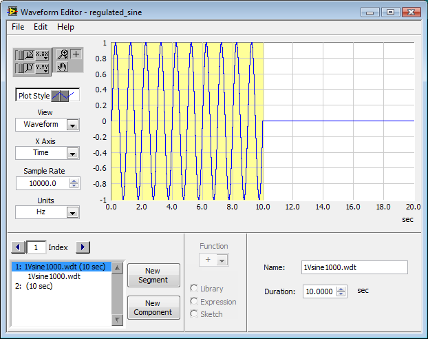
If you use the soft front panels, you can use the Waveform Editor to create a waveform that includes a sine wave for the length of your pulse and then the values of '0' for the rest of the time. Then use this waveform in the flexible front of the arbitrary signal generator. Simply create a component of sine as the first part of the wave and then add another element to a level DC '0' for the rest.
-
I am facing a problem with the beep.vi. I have a DAQ program, which acquired the signal and compare it to a threshold value. When a signal is out of range, a Visual and sound alarm has occurred. I use the VI beep.vi to generate the sound. Everything works fine except the sound alarm. It gives the table 1 d of type mismatch. I tried to fix this by placing it in a box structure. But it still does not work. If someone could help? Please find attached my VI. Best wishes to all visitors to the Forums of Discussion OR.
Ihab El-Sayed
published here: http://forums.ni.com/t5/LabVIEW/Playing-sound-based-on-exceeding-a-threshold-value-1D-array-data/m-p...
-
How to connect the generator of signals of Agilent N9310A chauffeur?
Hello
I have a N9310A of Agilent connected via USB to a system using Labview 8.2 and the Agilent driver. The system goes into remote mode, so there is a communication. I tried to change the example of "Agilent N9310A RF Output" to exit BF (low frequencies) so that I can check the control of the signal using an oscilloscope gererator. I get the following error: Hex 0xBFFF0015 timeout expired before the operation is complete.
I must then disconnect and reconnect the USB cable that the example can not find the device. What happens here?
I'm new to using Labview with tools
-Thanks for any help
-Matt
Thanks for your help guys. The problem ended up being with the firmware of my Agilent N9310A signal generator. I got the A.02.03 firmware version and an upgrade to the current version (A.02.05) fixed something called an unstable connection between the PC and the N9310A.
This works.
-Matt
-
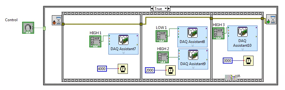
Is there a better way to generate the custom timed digital signals
I'm trying to generate the digital output from the top and down with delays on different lines. Each daq assistant is activate single line on a port USB 6501. There more complex high and lows that I need to generate variable time difference between high and low. There is codebelow that does what I'm trying to achieve, but for a model executing high and low signal is much of your time to do it this way. I'm sure there is a better way to do it, I'm not an expert on labview so I only discovered its potential. Anyone can suggest a more effective and a quick way to do it. I would like to hgihly appreciate. Thank you!
I've not shown in the code below, but using the DAQ assistant, I initialized lines at low logic level.
-
How to test if the rest is a decimal number or an integer?
Hi guys!
I want to check whether or not my rest of two integers is a decimal number. Also, if it is a decimal number, I wana it allows to do a thing and if its an integer, I want her to do something else. How can I do?
Help, please!
Thanks in advance.
Craster.D wrote:
The task is to divide two numbers X and Y and a LED lights up if the result/rest is a decimal number. It can be higher or lower than 1, is not serious. If it is not a whole number, the LED should light.
Great looks that you know exactly what you want to do, which seems to be the problem? You will find the functions you need in the digital, boolean and comparison scheme.
-
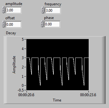
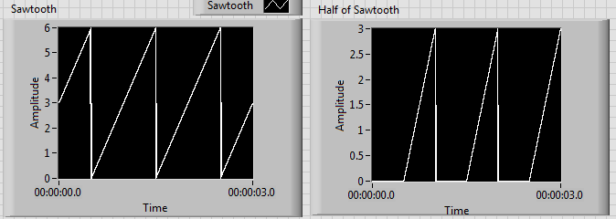
Results of increasing frequency generated unexpected behavior of the signal
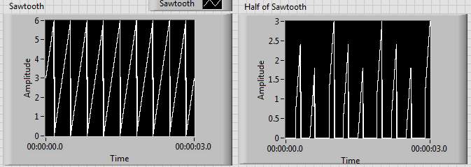
I'm generating a composite using a sawtooth wave, square, signal that produces the desired signal as shown on the left. Unfortunately, when the increase of the frequency beyond 1 Hz, I get undesirable results as shown on the right.
I tried to edit the news of sampling with no luck. I have also tried different methods to produce the desired signal. I noticed that before one of partial components of the final signal enters a relay, the increase of the frequency doesn't create unexpected results. Although, after its passage through a relay, the error starts happening. It seems that the relay is not suitable for higher frequencies, but I can't fix this unexpected behavior.
Frequency of 1 Hz:
Frequency of 3 Hz:
Another method that I tried was to use the "simulate arbitrary signals," even if I was unable to find a way to increase the frequency of the signal that results.
In addition, the signal has this grainy nature that I would like to make it smooth and continuous. Is this possible? I would like finally to reach a frequency of a few kiloHertz.
I have attached the VI.
Any help would be greatly appreciated. Thank you.
The problem has to do with the size of the block and when the relay actually sees the saw tooth cross the threshold.
Solve it, to perform a point-by-point check and build our waveform personalized to each iteration.

Maybe you are looking for
-
Impossible to update of the free applications
I have updates available on the free apps and also the latest iPhone update - I have an iPhone 6s. But when I try to update takes me to my payment information - card I recorded is an old account, I do not use and is currently in balance no - he said
-
Problem with stop on HP Compaq 610
Hello! I have a problem. My computer - HP Compaq 610 with Vista Home Premium installed - when I go on the computer stop is not going stop but restart after a few seconds. When I use Hibernate is workin corectly. What is the solution for this problem?
-
How can I access the system tray when it is disabled on the public computers?
Hi all I'm trying to access the icons on the test system such as: 'Remove the device safely', but I also try to access the other icons that would show in the system tray icon on the taskbar, when I plug my USB key into a USB port. The problem is, the
-
Receive error message: Windows 7 installation disc is not compatible with your version of Windows.
I bought windows 7 from the College Bookstore, and I can't install it - why this He says that the installation disc is not compatiable with your version of windows. to upgrade, you need the correct installation disc
-
When I start my lap top it says disk checking in vista (C): arrested
When I try to reboot the drive check, it won't work, I also tried to restore but it won't work becuse of vista (C): fault. now everything on screen is very big and I can't resize