generate the signal f = 50 Hz with NOR-9264
Hello. I am Sorin.
I need to generate a sinusoidal waveform with f = 50 Hz, U is 3Vrms. I have a C, OR-9264 module. Is it good? Or can it only generates SCR?
I don't have C modules: I for RTD, V, mA, universal and AO for V and mA.
What can I use?
Thank you.
It DOES not say that it displays up to 25 kech. / s (25000 samples per second). It's more than enough for 50 hz.
Tags: NI Software
Similar Questions
-
Apple Watch heart rate monitor, the signal can be shared with other devices such as the Garmin Edge 520?
Hello
No, that it is not currently possible.
-
Generating the signal as shown in the picture in labview
Hello
I'm using labview in 2011 and want to generate the second signal as shown in the picture attached in labview as I want to use it as input to implement adaptive filtering, if the first signal in the image represents the output of the adaptive filtering area.
May I know how to generate a second signal.
Thank you.
-
Connection diagram missing in DAQ Assistant generate the signalling block
This is my first post so please excuse the quality of my description.
When I double click on the block of data acquisition - Assistant, there is no tab connection diagram I can access to see how things are wired to the top. I have a NI USB-6211 connected by USB and it is used to control many different sensors and a power supply. Currently, he works for everything and is hard wired correctly, but only blocks DAQ Assistant has a connection diagram available, the other are not. One who has a connection diagram is used to measure a voltage. Others who do not are used to generate a signal. I would really like to be able to see patterns of connection for each block.
-Any help would be appreciated
-Thank you
You can always do like those who never use the DAQ Assistant and read the manual. Right click on the device in MAX and selecting "stitching of the device" works too.
-
generate the signal of decimal number
Hello
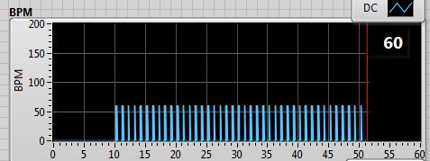
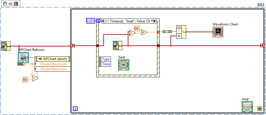
I have a program that calculate the heart rate from the ECG signal. I want to show the beats per minute on a graph with 60 s of the plot of the story.
Since the vi who calculate the heartbeat I get output the string with the number, only when the wave of the tip, then I convert it to a number and then I place the offset of a simulated DC signal.
(In the table below the beats per minute are always 60 because I'm simulating a sinusoidal signal with 1 Hz).
------>
It works fine, but I'd like to see not the summits but a continuous line from one point to another, such as interpolation.
in this case, it would have been a horizontal line to 60 BPM.
I thought to store the last value of the chain and keep it frozen until the next update of value.
Do you have suggestions on how to do it?
Concerning
Not clear what you get in the form of numbers, seems that you get too many zeros, and you get a decimal number or another 'dynamic '? value?
You pulse-rate information could be ~ 45 to > 180 values per minute!
You display the exact story of a minute? Maybe (keep the last ~ 300 values with timestamps and use an XY diagram) a graphic story can be configured to display
wait... Here's one way:
I fed a chart (with 256 points in history), with a waveform. the wfrm has only a single value in the array of values and a t0. The chart is configured to display the 60 sec. Seems to work
My simulation will display a min rate of ~ 45 BPM, but you can beat him

-
LabVIEW:EXE generates the error 1003 calling plugin with the type definition
Hi all
I am running LV 2012 on a Win 7 machine. I had this same problem with LV 2011, so I'm sure that's not associated with version/upgrade.
Go to a LV-built EXE, I try to call a dynamically loaded Subvi. I did it several times with success before, so I think I know how. I prefer to use the call by reference, but I get the error 1003 Open Ref VI (with the type specifier). If I use the type specifier, can I open the Subvi, but the State is listed as 'bad '. Then, I went to recursively through all the subVIs (~ 25 in total) and concluded that the only item with a status of 'Bad' was a type definition.
I checked several times, several different, that all ways the subVIs (and the definition of Type 'bad') are available to the Subvi dynamics. I did that the type definition is correct. I have also made sure the subVIs are stored as .VI files in the same directory and not within an EXE file. When I try to run the VI run call node, I still get the error 1003. I checked the path that displays in the error dialog box is the exact path for the Subvi (it would be for other VI properties and methods working properly).
Why can't I run a sub - VI loaded dynamically from an executable if it has a type (a group of 3 trails) as output parameter definition?
I just tested an idea: rename the library from project to project A create script. Now when it loads, it does not disturb what he must internally with externally called Subvi (dynamic). It worked the first time!

-
How to generate the display of mobile list with data of the user
I try to develop a simple mobile application (mobile jquery) in Dreamweaver.
I want to create a list of names of people from entering information via a form.
The list would then be based on criteria that is last name or Department
This require additional database programming or it is part of jquery mobile?
I know it sounds simple, but I'm not a programmer, so I'm just my feet wet here.
Thank you
DW has no capability of database currently. If you do programming server side with PHP and MySQL, there are commercial extensions, you can buy separately from the Web help and area of DMX. But it's all depends on you how to work with data MySQL & PHP. Development of applications for mobile devices is still a different learning curve. I think DMX Zone has some extensions to help with that as well.
http://www.DMXzone.com/go/32214/mobile-app-development/
Nancy O.
-
Big latency constant to generate the signals AO which is an immediate copy of the signals HAVE.
-
Synchronization of the signal with PCI-6602
Hello
I need to generate three signals that must be synchronized.
To do this, I use a PCI-6602.
The first signal is used to trigger a device, the second signal is used to simulate the noise.
The third signal should wear the noise so that it starts before the trigger signal and stops shortly after the trigger signal.
The signals are then combined with an external logic circuit.
(To see what I mean, see the first PDF).
I use a fourth timer to synchronize all other clocks, but the three signals are beginning to run before starting the timer task. I have this evaluated using not to no and a oscilloscope.
The trigger and gate (first and last signal) are below 100 Hz, the noise signal is about 200 kHz.
At least the trigger and the door must be started synchronously, otherwise the waveform is not what we want. The noise signal didn't need to be synchronized.
I am sure I am missing just a little detail here, maybe you can show me what I missed.
Please check my screenshot of LabView to see what I've done here.
If you want more information about the VI, I can take apart a little and send it, too.
Try using start to the outputs of the 3 meter (see attached VI)
-
Looping/cycling through frequencies with the signal to create VI
Hello
I am trying to operate a PZT with a given signal (of a formula) and to save the output of the sensors. I use a PXI of NI 5421 to generate the signal and an NI PXI 5105 to record signals. I made the attached code that works well, however, I'd like to be able to the frequency and the number of samples (the number of samples is function of frequency) in the VI of signal to create loop so that I can scan a range of frequencies. Could you please help me. I can't find a way to control the frequency outside the edit in the Properties window.
Thank you
Casey
Sanjay-thank you
I just thought of it. I Redid the vi and when I ran an error that said come the input signal must be an integer value to a multiple of 4. I made a few simple changes to make and after that everything worked as expected. I guess that the entrance of waveform looked ok but not get operated by material, unless it is a multiple of 4.
Thanks for your help,
Casey
-
Duration of the individual sample - OR-6220 and NOR-6723
Hello
We are acquiring data through NOR-6220 and NOR-6723 Renault in our laboratory. The data acquisition process through Data Acquisition Toolbox of Matlab, where we put the sampling rate of the analog inputs to 10 kHz - or 0.1 sec per sample. Now, we wonder what is the time of the sampling process, i.e. the period during which an individual sample. Is there an average process for the duration of the sample (0.1 s), or during a window much shorter? In the latter case, how would know us the exact duration, and it would be possible to control it?
In our case, we see resistance jumps in our system. Even if we get a range of resistances, we suspect that these jumps can actually be between two distinct levels; It is possible that the process of averaging during the sampling results in obtaining intermediate values between these resistances. Have a shorter window of sampling would be useful in addition to interpreting the results.
It seems that this could be a trivial question, or who might be a Matlab thing rather than a thing of the card. Bear with us in these cases; We have made an effort to research on the problems on the forums and elsewhere
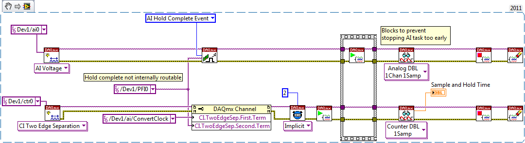
. Thank you!There is a sample circuit and hold on the device. The clock to convert marks the beginning of the sample interval, while the complete signal of cale HAVE mark the end.
I don't know if the waiting time is nowhere specified, but you should be able to measure like this (example LabVIEW... I don't have MATLAB or the Data Acquisition Toolbox unfortunately):
On my PCIe-6351, I get a waiting time between 440 and 450 ns. The 6220 can be different, but I hope that gives you an estimate. This setting is not adjustable.
Having said all that I don't think it's relevant to your question. If your input signal varies between different levels and you want to try that once it has established a new value, you must ensure that the task of IT is synchronized to what generates the signal.
Best regards
-
How to speed up loop DAQ triggered using NOR cDAQ-9174 with NOR-9215 and NOR-9402
Hello
I use LV2010 and NOR-DAQmx 9.2.2. I have a NOR cDAQ-9174 with a NEITHER-9215 4 channel 100 k simultaneous ADC and NOR-9402 4 channel DIO module trigger and reset.
We run WinXP sp3 on a Dell M4400 core 2 duo @2. 26 Ghz.
I used the code example NI DAQmx for acquisition of tension with trigger HW. My goal is to try all 4 channels on the 9215 simultaneously when a trigger is received on channel 0 of the 9402, after data is read, I use channel 1 on the 9402 to reset the trigger of the target material. I have a version of this work, however the maximum event rate is ~ 16/second. I have the Setup 9215 for finite samples / 10 samples per channel which is ~ 400uSec of conversion time and I realize he is above in the appeal of vi, but ~ 50mSeconds worth?
The target detector can put out up to 1 k / event triggers / seconds. Only, I received a rate of 8 per second and I added the NOR-DAQmx control vi driver and chose "commit" this did double the rate.
My question is what is the maximum rate of loop for these devices (trigger/conversion/reading device / reset) and start over? I noticed that just let free the 9215, carried out using the 'Acq & chart internal strain Clk' raised only the rate of events up to 20 Hz.
Thank you
normbo663
Hi normbo663,
You can get this works far better assuming you have an available counter (there are 4 on the backplane of the 9174).
DAQ Compact supports the tasks of meter output "redeclenchables" that can be used to generate a finite pulse train. You can set a task of finished meter redeclenchables output to be used as sample for your task of analog clock. The task of the meter output will be re-Army (less than 12, 5-25 ns) as soon as it's finished out the last pulse. The task of analog input would be configured to run continuously, but it would only sample based on the output of the meter triggered. For an example, see here.
You can reference the internal counters on the cDAQ without signals through a routing module using: cDAQ1/_ctr0 (right click on the chain counter control, then select i/o name of filtering and check channels internal to add these options to the drop down).
Thus, with the tips above, you should be able to immediately re - arming your analog acquisition on the 9215 using one background basket counters. It seems that the second half of the application is to use a second channel on the 9402 to reset the trigger of your DUT. You can deterministically generate this signal so by configuring a 2nd redeclenchables meter out task (single pulse, but this time). All you need to do is the initial delay on the appropriate value for your analog acquisition. Trigger this counter on the same PFI line that trigger you your analog task from.
Using counters to generate the signals you need in a deterministic way, the loop becomes is no longer a problem (as long as your input buffer does not overflow). You may need to re-read several triggers at the same time for the loop to keep (for example to read 1000 samples each, which would correspond to 100 triggers 10 samples).
Best regards
-
Improve the signal from the router
Hello, I need a Wi - Fi Range Extender, I take the powers a little signal.
The technology of these accessories and take a signal and strengthen it as a router or a switch-> Range Extender WiFi-> and the client has an attenuation of the signal?
It remains the same as that which carries the router?
It strengthens it so that you have the strongest signal for customers.My problem.
Router standar Telecom in an apartment of the third floor of a building where the ground floor it is local (shop with three slides) who must pick up the signal. Now that with the router, the signal arrives but, weak, and there is a local point where the signal and the stronger, enough to be able to navigate with a non-performing smartphone.We would like to put a Range Extender Wi - Fi to the strongest step to bring it to the customer.
Your WiFi Range Extender are all uquali for the work that I do, or I have to evaluate some of the same characteristics.
I explained enhancement, signal loss?
Thank you.
Hello creatt
An Extender, you should get better report you would like to place somewhere in the middle where you need wifi and the router to get the best coverage.
DarrenM
-
Using PCI-8532 with NOR-DNET 1.6.6 / NOR-DNET 2.0.2
I have a PC with the following configuration test set-up:
- Card PCI-8532 DeviceNet
- Windows 7 Enterprise, SP 1
- LabVIEW 2010 Runtime
- NOR-DNET 1.6.6 with MAX 5.0
- No environment of LabVIEW Development
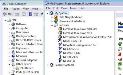
- PCI-8532 isn't available in MAX and Windows Device Manager indicates the card as "PCI Device" with an exclamation mark.
Here is a screenshot of Windows and MAX Device Manager:
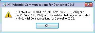
I can't install the NOR-Industrial communications for DeviceNet 2.0.2 on this computer because I get the following error:
Well, I have two questions
- How can I install and use the PCI-8532 and see with NOR-DNET 1.6.6? If this is not possible:
- How can I create an executable file on my system (portable) development with LabVIEW 2010 or 2011 LabVIEW and run this executable on the test set-up. I currently have on my development system:
- Professional 2010 LabVIEW and LabVIEW 2011
- NOR-DNET 1.6.6
- No hardware OR at all
- I have to install the NOR-Industrial Communications for DeviceNet 2.0.2 on my laptop (my development system)
- This will interfere with my current NOR-DNET 1.6.6 and then I select which driver to use at compile time
Thank you
Nick
Nick HY,
No, it is defenitely not a replacement yet and I will work with our Web Department who make clearer on our web page.
The development of the new API is pretty well done, but based on your feedback, we are planning to improve compatibility, so you can for example use the old APi 1.6.x and the new APi of 8532 on the same machine, so you can use the old and the new material on this same machine. Which would be important for you?
For the moment we intend not to allow only one type of material on the same machine to save you development time. Let me know what you think.
To clarify the situation today: The InCOM for Devicenet component is not part of LabVIEW. It's just a very simple means of communication with the I/o variables and blocks of function for the MS. The driver should install fine even without installed LV. The error message is quite a Bug on our side, and the solution would be to use the Builder installer LV to create a new installer that can install 2.0.x Incom Dnet driver without having installed Lv.
And today, you should be able to have the 1.6.x both pilot 2.0.x in parallel and use the API 1.6.x with old boards yonce and the variable approach of IO 2.0.x with your new Board of Directors.
I'll keep this post updated as soon as we have a stable Beta available I'll post something.
DirkW
-
Jitter in response to signal generator of digital dashboard by using trigger nor tclk with digitizer
I've written a VI that uses NEITHER tclk to synchronize a generator (PXI-5422 named FGEN1) and a digitizer (PXI-5122 named DIGITIZER1). There is also a clock card TIMING3 generating a digital camera.
It seems that can probably be explained by the way TCLK to synchronize, but I don't understand all the details. Could someone help explain this to me?
You are right. NOR-TClk ensures that all synchronized devices start at almost at the same time, to the same sample clock, with timing very tight. Sometimes, the level of synchronization with the devices OR TClk-synchronized beats at the level of the synchronization of the instruments of some competitor channels in the same device. But this is not free, there are compromises and added additional jitter for trigger response time is one of them. Here is an attempt to explain why:
When you use NEITHER-TClk and send a trigger, the devices will respond to relax on the next cycle of the clock once made the trigger signal to the device. Let's say you have several devices all of them even configured with the same clock frequency. You block the signal of PXI_Clk10 using their PLL, so they drift out. But each unit's clock edge will be off, clock +-0.5 cycles. If you send a trigger to each of them, they will respond on the next clock cycle whenever it is, after the arrival of the relaxation to each device with different propagation times, whatever they may be. You get a single clock cycle of jitter on reaction of device to set it off.
When you use NEITHER-TClk, several things happen: all devices are locked on the PXI_Clk10 signal to eliminate drift. The device clocks are then adjusted to a period level secondary clock. Very very tight. Then a clock signal common, slower called TClk is produced inside the devices. All the generation of trigger are delayed to be sent to the next rising edge TClk, and all consumption trigger is delayed to be received at the next front descending TClk. This way you make sure that propagation delays don't mean one of the devices does not react to the trigger until the next clock cycle.
That's why you see jitter above the reaction time of relaxation. When you add devices with different clock settings, so the frequency of the TClk can be slower for a divisible frequency in the device clock frequencies everything is possible. This causes the trigger jitter of reaction time be even slower!
I hope this helps you understand what you see.
Maybe you are looking for
-
MacBook Pro 15 '' (2015) overheating "
Hello, I have looked through all of the messages on MacBook overheating in this forum, tried almost every step, battery, saving of the SMC fan control mode, but looks like nothing helped. My macbook pro 15 "is overheating a lot, sometimes when I'm on
-
El Capitan doesn't let me choose default mail.
I now El Capitan. I use .mac as my default mail, but now gmail has been crowned as primary and by default. How can I get my primary .mac again? MacBookPro to 2015.
-
HP laptop: find the model and serial number
I'm trying to place the model and the serial number I can order some new keys as the letters are worn. I looked everywhere in the machine, including removing the battery. Doesn't seem to give enough information, according to the order made multiple
-
Internet host and network disconnection continuous
Background: A contractor for the cable company spliced my line so that the new neighbor could get cable (only my address has been marked on the box and there was a cord connecting it under their fence). I called and they sent someone who said they wo
-
My desktop background is black, regardless of what I do. I tried to change the theme and use a personal photo, but it just says: black! Can someone help me?