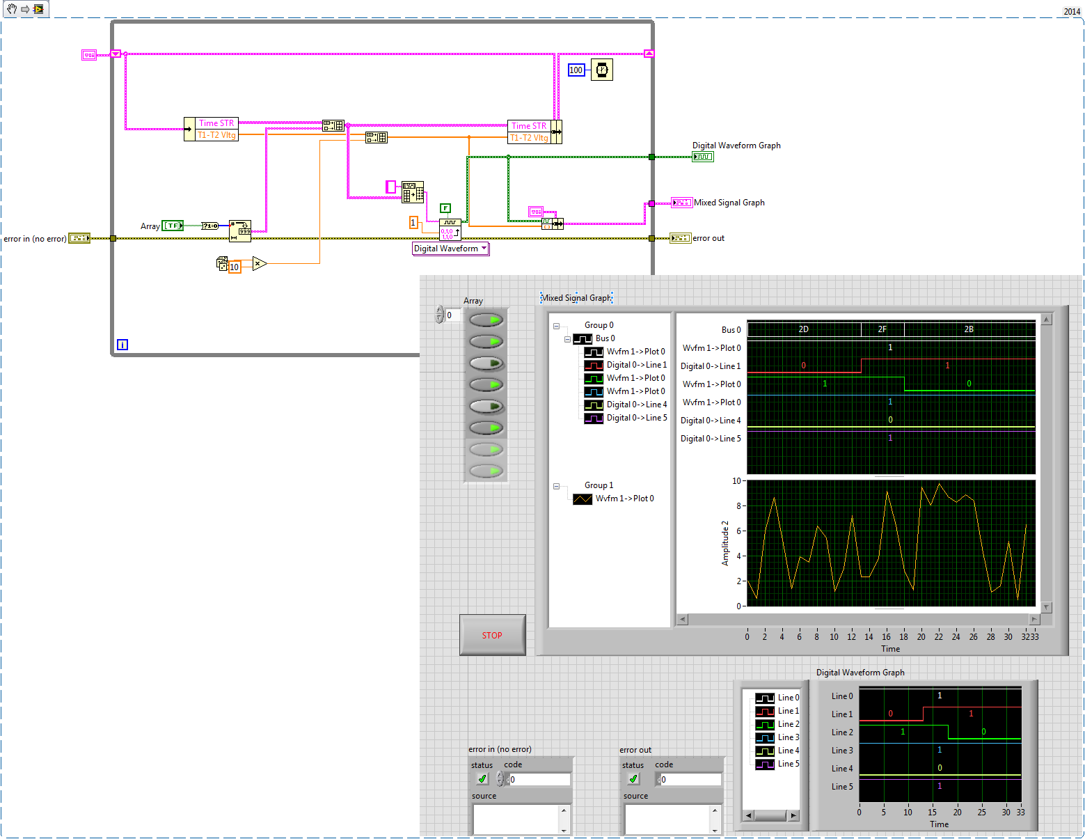
graph of mixed signals of compensation with 2 areas of land
I have a graph of mixed signals from zone 2 simple plot. When I try to reset or clear the chart by writing a 0 to it dashboard, it bombards. Anyone know what is wrong here? Seems like it should be essential to the functioning of this object.
It's seems to work for this case. However, I had tried in the past and he had problems with some things too. I even had the code still there to generate an array of the same size, but what makes all 0, but it was not connected to the entry of the chart in my code now. Instead, the chart was hard wired to a constant with a single element to a value of 0 0.0. We can call it a success so far. Thank you
Tags: NI Software
Similar Questions
-
How to reset the graph of mixed signals automatically?
How do you resets a graph of mixed signals automatically?
My idea is like that - I'm drawing a chart throughout the day... Then, at 19:00, I want the chart to erase. There will be a break until 06:00. It will therefore start a new graph at 06:00. How can I do this? It seems easy, but I can't find the solution. Thanks in advance!
redhotsneakers wrote:
Why local variables are useless?

It's a missquote, I'm afraid: I didn't say local variables are unnecessary, even if some would align themselves with this statement. I said that they are in your case. In VI you have published everything first, you are passing data from local variable that can be better spent by wire sind, the variables are literally next to each other. While you might get lucky in a program of this size, it can cause a world of problems in a larger application.
Back to your problem: after watching your new VI, I'd say you're almost there. Separate features in the two loops does not seem necessary. Instead of the value property, you can try the method reinitialize I mentioned earlier, that should do it.
Then you can add a feature that reinitilizes only once by comparing the range in the previous iteration.
BTW: this select function is code of rube goldberg. Why not use the Boolean result of the node equal to the cases.
-
How to dynamically add a plot to a graph of mixed signals
I have a graph of mixed signals where I'm plotting a signal from a time axis. I'm trying to dynamically add a second plot to this graph against the same time axis (with a different scale of Y), but when I built a 2D array and try to connect in the graph (using a local variable) I get an error of size mismatch. I know for sure I did in the past (cable tables with different sizes for a same MSG) with no problems but, today, for some reason any I can't solve this problem.
Am I missing something?
Yes, you're probably writing a table 1 d somewhere that is causing to accept only 1 d. To address your problem above, just put a table node build in whenever you have a 1 d table and it will be just a 2D array with a single line of data.
To add a field to your current locations, your screenshot above should work once the plot knows that he has to accept the 2D tables.
Reading from a local variable, change something and then write about it once again can lead to a lot of issues down the line. Race conditions are a pain in the butt, so get rid of that sort of thing is good to do from the start. I didn't know the rest of your code, so I don't know how you treat it, but just keep in mind that you add to your software.
-
How is - I size the Group zone oin the graph of mixed signals to meet my signal names?
I have a graph simple signal mixed and I programmed my signal names and they are longer than the width of the component group existing on the subject, and I want them to be visible. How can I resize the graphic components because I wrote the names to the object? I know that I can personalize the thing, but y at - it a method or a property that I'm missing here?
It seems that it is a known problem. You can change the size of the legend by using a property node for waveform graphs, but not for a graph of mixed signals. A good work-around would be to right-click the gray bar between the legend and the plot area until your pointer changes to the resize tool. You can then size it is large enough to show the whole legend. It is a question that is configured to be resolved in future versions of LabVIEW.
-
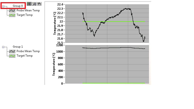
How to trace the temperature and voltage using the graph of Mixed Signal
Hello
I use the NOR cDAQ-9178, module NI 9214 (temperature) and the module NI 9201 (voltage). My program allows the user to choose among 3 different tasks, Masurement of temperature, voltage, or both. When you select the task for temperature and voltage measurement, I was drawing all channels on the same graph. I was invited to separate channels of temperature and voltage and draw on a split graph, using the same category axis. I tried stacking, but could not control where each parcel channel went. I think the Mixed Signal graph would work well. Everything works and records all the data of the channels to the files, but my plots appear not on the graph, although I can see the change in scale numbers. I think I can use the cluster incorrectly. Can someone tell me what I am doing wrong? I selected the 'Plot Visible' option, but the plot is not always displayed. I've attached a zip with all the screws needed to run my program. The main VI is "Voltage_Temperature_SingleTask_Measurements_MAIN.vi"... but everything must be downloaded to the program works. Please help... Thank you.

Hi mzhlb,
I complained only the expressVIs.
Why not use simple IndexArray function to get bots waveforms of your waveform table? (I faked it your DAQmxRead with functions SigGen).
-
Graph of Mixed Signal: how programmatically change the name of the group in the legend?
Hello LabVIEW community,
Can someone tell me the property node that would allow me to change the name of 'Group 0' programmatically in the legend below? I have searched through all mixed methods graphic Signal and nodes of property with no luck and should just be overlooking it.
Thanks for your time.
Steve
Hello Electromecha,
Unfortunately, there is not a property node associated with the name "Group" in the legend. Several others have made that suggestion over the years. I recommend kudoing the idea in the IdeaExchange.
-
Mixed signals with the buffer graph.
Hi I'm new to LabView and I have a really basic question.
Here's what I'm trying to do.
1. I use chart of the mixed signals to display some acquired DAQmx signals.
2. I have 3 separate field areas.
3 X - axes of these areas of land must be completely in Sync.
that is the main reason why I want to use graph of mixed signals.
4. I want that signals are displayed as table of waveform,
It's the waveform data are not deleted during update
and I can scroll to watch old stuff.
5. I also want to save the data as numbers of I can also
do all sorts of calculations with them.
Now with my vi, the graph gets refreshed and crushed
each sampling period and only a small fraction of the data I want is
shown on the screen. (I want to these fractions to get annexed by)
order of chlonological...)
I guess that it is a fairly common problem for a beginner.
I could easily do in C or Java, but rather difficult to do on the GUI.
Any help will be appreciated
Thank you!
If you want to see the temporal evolution of your chart, simply change the x-axis not autoscale under properties of the graph. You can use align your waveform in programming > wave > align times. You can activate the option to scroll by right clicking on the graph > visible elements > graphic palette.
There are many options for data backup. The quick and dirty is to enable indexing of your time loop and thread to write on the worksheet to the title of programming > e/s file > write in the spreadsheet file. Keep in mind that the file is a txt file.
Post your code for help.
-
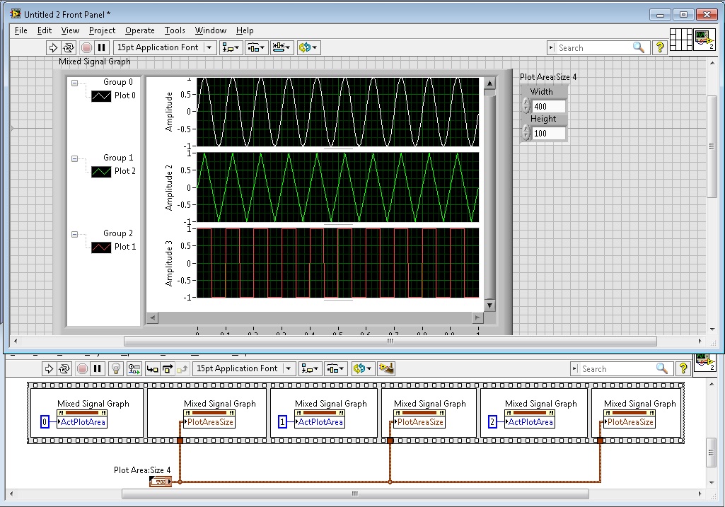
mixed-signal graph size automatic
This seems simple, but is there an option that will automatically format all the graphs on my graph of Mixed Signal to the size of my VI? For example, if I increase and decrease the size, the graphics remain a constant size and I would scroll to see them. Secondly, that all graphs have the same vertical height, instead of me manually by dragging the separator to try to make all equal in size?
Right click possibility and also space all the graphs and auto fit all graphs would be very practical! I can't find the option for her.
Image attached showing the spacing I'm talking about.
Thank you!
Hello
This can be done programmatically with the nodes property. The trick is to use two nodes of different property of the to do.
We must first define whatever parcel we want change to be the active plot by using the Active plot area property node. We can then define the limits of this plot by using the node property parcel size of the area, which is located under plot area > size.
Good luck!
-
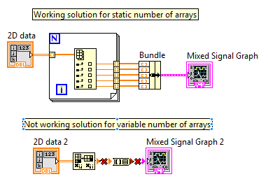
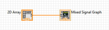
Convert a chart 2D with various sizes for Mixed Signal
Hi all
I have a table 2D with, for example, 5 signals with each 100 data points (so a table of 5 x 100).
I want to show each table on a graph of mixed signals. I have a solution that works for this problem (see attachment).
My problem is that the number of signals and therefore the size of 2D array is variable. So the next time I run the VI, the table can be, for example, an array of 6 x 200. In this case I can't show all 6 plots on a graph of signal mixd my working solution.
I was looking for a 'Table 2D to the cluster' function in Labview (see attachment) but unfortunally it is unavailable (perhaps a tip for developers
 ).
).Is there someone who has a solution for my problem?
Thanks in advance,
Patrick
Why can't we just plug them directly together? Mixed Signal graphics take an array as input 2D type.
-
Mixed signal graph - data digital unable to see on the graph
Hello
I'm tracing analog and digital data on the graph of mixed signals. I'm not able to see numbers on the graph, but when I export data to excel it shows all digital plots also. According to me, Miss me some settings.
Please check attached VI for reference and let me know if anyone knows the solution
Kind regards
Jaysha
I changed the frequency of sampling to '1 '.
-
Extraction of subset of mixed-signal graph table
When you zoom in on a graph of mixed signals, is it a property node to get the min and max index in the array of signal, instead of the minimum xscale and the maximum value of xcale?
Indeed!
Thank you
-
graph of the mixed signals on wrong tab
I have alarge program. In one of the screws sub in the first run a graph of mixed signal appears on the wrong tab. If I clict on the second tab, whaere graph must be, it seems normal. If I go back to the first, the ghost of the chart image is gone.
Also, if I left the program normally process in the second executionl, the ghost image disappeared.
Y at - there anythign I can do to stop this behavior?
I already tried to reinstall previous versions od my software, but it continues to be.
-
Mixed signals graphic memory leak
We have an application where the data is received over TCP, deserialized and fed in a graph of mixed signals (8 analog, 2 digital buses of 4 bits each) periodically (approximately every 500mSec). Analog and digital data are combined in a cluster and fed directly into the terminal of the graph, although the terminal is located in a structure of business with a button "pause". It is built into an executable file that has a slowly but surely increase use of memory (about 4 MB per hour) - unless the pause button is turned on. The culprit must be the graph, no?
I did a vi to reproduce posting here: copied the source vi, removed only the TCP part and replaced it with random dummy data. While the copy also has a growing use of memory, that he does in the biggest steps about every 15 minutes. No idea why this is. I'm looking at the memory in performance monitor, the counters to "private bytes", if this is important, see attached screenshot: blue is the copy, the Red is the original and to halfway the graph, two of them were on a break.
Looking around, I saw it but because without more information, it is difficult to say if it is related.
Is that all I could do to narrow down the problem? Anyone knows a reason why he might flee? Currently, we have Labview2013, maybe someone can try in a newer version to see if the problem is still there.
Thanks in advance!
Hi Stijn,
I can say that R & D are aware of the problem and is waiting for their work, but I can't give a timeline on the resolution of this problem, because I don't know what are the priorities for improvement.
-
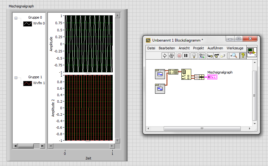
plot area chart mixed signal displayed
I have a graph of mixed signals with 2 areas of land and am trying to optimize the flexibility with the screen space and look at a. Sometimes I want to see the two draw areas in display at half the height of the graphical display of any mixture GIS and sometimes I need better display resolution that makes me want to make one of the plot areas fill the full graph of the display area and then simply scroll down to see the other.
What is the best way fo doing this if I want to press a button to easily switch between these 2 views? Use display port size and properties limits or something else? (The properties of ports and view limits are not well-defined dimensions of what I can find either)
Hello
You can do this by using a combination of several nodes of property. You can use the PlotAreaSize property to manually set the size of the individual parcels (not the viewport). Note that you need to use the ActPlotArea property to enable each parcel before resizing. After you set the size of the plots, set the size of the window using the window-> size-> all the items property.
I advise to use a structure of the event to change the properties when you click the button to toggle between the two views.
Hope that helps.
-
Programmatically formatting graphic mixed signals
I am writing an FPGA application where I am acquiring data from a unit under test (USE). The PXI-7842R digitizes 3 groups of signals:
1. an analog voltage monitor
2. 5 digital signals connected to the analog inputs (limitation of the pinout of the connector) and converted into Boolean values
3. 11 digital signals connected to the digital inputs
That's a total of 1 analog and 16 digital inputs. I want to show them on the same graph, so I used a graph of mixed signals.
To avoid reconfiguring the graph of mixed signals, everytime I open the app, I wrote a Subvi to programmatically format the chart. I pass a reference to the graphic indicator of mixed signals and try to adapt it to look how I want. The indicator has been designed as a cluster of analog waveform 1, 2 bus waveform Digital 5 signals 1 waveforms digital bus 3 and 3 different digital waveforms. The Subvi is called inside the host VI using a statement box controlled by the 'First Call' function. Then host vi bed a U32 to the target-to-Host DMA FIFO, formats the data in the correct order and the beams while an indicator of mixed signals. During an attempt to format the chart programmatically, I get errors in property not valid which seem to depend on State. Unfortunately, the documentation of the properties seems to be quite uneven for errors I get. The Subvi attached through the following sequence:
1. configure the shared axis and shared properties (IgnoreAttributes, ShowBusseswithLines)
2 set up the area of tracing analog scale Y (superior plot, area 0? documentation is inconsistent on this point)
3 set up the area of tracing digital scale (sector 1) Y?
4. name the digital bus (3 in total, should be numbered 0-2).
5 name the plots
Correctly all steps 1 through 3, but I get an error when you try to set the Active Bus to 0--> ' #1077 Error, invalid property (Bus Active)»
I tried to set the Active plot area to 1 before setting the bus, and I get the same error.
But then sometimes if I rerun the VI host without change, the Subvi ends correctly (even if the area of the scale becomes huge and empty). The only way I can remove the errors is to set the for loops to iterate 0 times, allow the host VI run a few cycles, stop the host VI, remove the constants 0 and run again. And then there is no property errors.
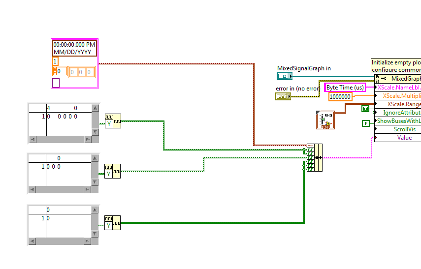
I then tried to create a constant of mixed signals with the correct sequence of the empty slots and it allows to set the MixedGraph::Value property at the beginning of the Subvi. Now error #1077 occurs at the level of the active node before Plot Bus Active node. The thing first on the definition of the constants of iteration 0 does not help when the value property is an initial value.
Here are my questions:
1. the ActivePlotArea property must be configured to use ActivePlots or ActiveBusses, or is that only for sizing and moving areas of land?
2 - is ActiveBus ActivePlot to define first of all necessary to property? for example, if I have ActivePlot = 0 (for analog plot), the ActiveBus property will always fail?
3. what else is necessary for the property ActiveBus of function call?
4. why the Subvi is failing the first time but succeed during subsequent calls without be initialized does not yet reach every time after you initialize (except for loops are set to 0 and Subvi finishes once)?
5. because I show a legend of the plot, I don't want the names of digital signal appears again in the scale box Y. How can I hide the names but to allow the plot area to extend completely to the legend of the plot rather than leave a large area of wasted white space?
Hi Nick,
The reason your Subvi does not work, it's the bus you want to change do not exist when you run.
If you want to run this sub - VI like initializer, you must first initialize all of the plots you will be change.
I've included a small example of how to achieve this by grouping together a constant of analog waveform with some constants of digital waveforms and food nerd in the property "value" Mixed Signal curve.
Maybe you are looking for
-
After you download 15 FF icon chgd on a square box with Green Cross. FF works fine why green cross
Other icons of FF in my system remain the same as before. Why the green cross. I liked the old icon better.
-
I tried dragging and deleting MyYahoo in the homepage and it resets to Bing, whenever I have reconnect.
-
Updated by Satellite L50 - A - 14 L for Windows 10
Hello worldI'll update my L50-book - A - 14 L Satellite 10 Windows. I have read the procedure on the Toshiba site, but I have some doubts. I read in the page with the list of software updated, "Toshiba recommends installing this component which has b
-
I wanted to restore my computer laptop back to factory settings. So I went into settings and navigated to the update and recovery, recovery and then clicked the option restore factory settings. I had several partitions then asked me if I wanted to de
-
Plug and Play drivers: Instrument of Identification error (pumps Ultra PHD at Harvard)
Hi all! I use the LabView drivers to control a unit of Harvard pump 70-3007 and fall on some issues. (I'm controlling through the USB port). Driver: http://sine.NI.com/apps/UTF8/niid_web_display.model_page?p_model_id=16026 Plug-and-Play site: http://