Graphic intensity scale and the Transformation of coordinates
Hi all. First post ever so please bear with me. I'm trying to plot the data that I am buying a load cell in coordination with the X - Y position, I get my motion control system. The news of load cell must be the z axis. I'm receiving the order of movement data, then acquire the load cell signal on average and store them in a table. I would like to plot these data for each movement of x and there axis so that I can see a real-time mapping of the data that I have gained. I joined a program that computes XY positioning required with load cell data simulated by a random number. Drawing the x - y graph coordinates XY is the standard path measurement I use. I wish that the graph of the intensity to draw the same way with the correct details used on the axes. If I could put the xy graph and the graph of the intensity, it would be a major bonus. I can't wait to hear any response that helps me on this one. Thank you in advance for your time and effort. Only, I'm stumped on this one!
Keith
I'm sorry. Realized that I do not understand a Subvi. Deleted so the program should work if download you it directly. Just a few notes: Spray size in inches and normally between 2 and 20 inches, degrees lateral spray angle is normally between 10 to 45 degrees. Angle of transverse jet is normally between 2 to 10 degrees. Pin diameter is in inches and usually falls 0, 020-0, 080 range.
Tags: NI Software
Similar Questions
-
Hello..
I have a table 2D numerical values... they are of magnitude of some complex numbers in the following order (3.25085E + 7, 2.87497E + 7... so on). How can I make the scale on the graph of the intensity automatically in this range. ???
Thank you
Hello cheggers
thnx... I tried with X evolve range and... I didn't notice the Z scale range. Now it works perfectly.
Thnx
-
Change the scale and the legend of an indicator
I create a VI shows the current temperature and the speed of the wind on 2 separate indicators. I added a two 'select functions' button controls to convert the readings between English and metric units. No problem. Now I want to change indicators it legend and rank (minimum and maximum values) also when the key is toggled. So if I push the button to select the metric values for these readings of the scale values and the legend are changing too. Thanks in advance for the help.
Right-click on the indicator, then press on "create the property node >.
Then select the following properties:

-
Profiles BlueTooth scale and the GATT
Hello
I use an example of GATT BlueTooth to activate connection with scale of Wahoo. The scale is the utility (after it is combined and registered in the BlueTooth settings UI). It lists several standard services and the other (0 x 1901) is not in any of the documents of the GATT on the site of BlueTooth.
In addition, under this service, there are three characteristics listed, one of which is 0x2A1C, TEMPERATURE_MEASUREMENT...
Now, since there is no profile of the GATT for WEIGHT, Wahoo using temperature profile of the GATT to pass the measure of weight through?
I've heard of Wahoo. It turns out that the service of weight exist, but it is not official. Example of application of the GATT sniffed out correctly, but not could not name it

(Not official)
-
choose between the entitlement and the transformation?
When it comes to choosing assign and when to choose the transformation? Is there than to the extra features to assign that aren't there in their transform properties?Lol the processing activity is nothing more than an entitlement (internally) that runs ora; processXSLT() method. IMHO-
1 assign must be used to copy less (preferably operations<10) where="" source="" and="" target="" structures="" are="">
2 transformation should be used when multiple copy operations must be run with the complex mapping (usually where source and target are quite different in their structure)Kind regards
Anuj -
The scale and the relationship between the problem of points
I had a few problems with setting the scale of the objects and their appearance before and after the scaling.
The relationship between the points change when I change things, and it's a little embarrassing.
Before that I put across that circle with an arrow, it looked like this:

Then after that I put across it, the lines on the arrow were not in place:

It happens very often when I am scaling of paths in illustrator. Is there something I can do to prevent it? Often I make things evolve upwards or downwards and it is a little painful when I know I'm going to screw up the path.


Go to the drop down at the top right of the Panel processing and disable "Align new objects to the pixel grid."
Edit: If you select 'Web' in the new Document dialog box, "Align new objects of pixel grid" is enabled by default, at the bottom of the box. You can choose to disable it there before OK-ing the creation of the document.
-
Graphics refresh rate and the writing of text problem - error 5
Hi guys,.
I'm new to labview and have encountered some problems when I try to write to the file. I use USB-6259 with Labview 2009 to acquire a number of channels I want to analyze later in MATLAB, all at the same time providing some limited analysis in real time. The experience is to use lasers to calculate the position of a rotating cylinder. I wrote a quick vi using the DAQ assistant to acquire channels and provide a polar diagrams showing the counterclockwise movement as it turns what is ideal. The problem is that, because the cylinder rotates at up to 6 Hz, graphical needs updated very quickly I realized by using a buffer size lower compared to the sampling freq (sampling freq between 5 k and 10 k, buffer around 200). This does not seem the best solution. Also, when I try to write in the text, the following error is displayed after a few seconds:
Error 5 has occurred writing to measure file-> Displacement_Rig.vi, or the possible reasons:
LabVIEW: File already open.
=========================
NOR-488: Command requires GPIB controller system controller.Can someone point me in the right direction? I tried to create a loop of producer/consumer, but I'm not convinced that it works with my limited expertise. I attatched my vi, although I warn you, I'm new to labview...
See you soon
Hello Ipaza,
I watched your VI and found that there are has some problems in the architecture of your consumer producer loops.
You can get a pre built loop producer consumer using the templates on the start screen.
I copied the majority of your code in such a model. Could you test this and let me know if this solves some of the question.
With regrads,.
-
filters, constraints, and the transformations in odi
Hello
When I want to add a condition I can do
(1) adding constraints and references with this data store or
(2) creation of filters in the diagram
So, what is the difference between these two?
(b) how business rules and integrity constraints are different transformations in odi?
PDF, said business rules and integrity constraints can be checked at the level of data extraction and
transformations can be done by loading data to target using the features of target databaseJin
one)
wrong explain this with an example.If I create a filter to tell the age > 18
Then all the records that have the age< 18="" will="" not="" be="" processed="" at="" all.="" in="" other="" words="" this="" data="" does="" not="" even="" enter="" the="" flow.="" its="" like="" stopping="" it="" at="" the="" entrance.="" mostly="" used="" when="" we="" do="" not="" want="" some="" data="" to="" be="" processed="" at="" all.="" say="" for="" this="" example,="" a="" person="" less="" than="" 18="" cannot="" be="" married.="" so="" we="" dont="" need="" to="">
But if you define a constraint saying age > 18 on target then all records with the age below 18 are moved to the error table. In contrast to the filter, all the data are processed. During the flow, constraints are checked and we have options(Flow/static) to either move the records to the table of errors only. or (table errors as long as target table)
Filters are generally defined on source.
Constraints are usually defined on the target.(B)
Another example.
The rules are certain conditions that you can set using "forced" feature in ODI. Here, we can apply this business rule to catch false documents.
Ex: age > 18.Whereas a transformation (made in the mapping) is something like this
If your source stores the name of the Middle first, 3 columns, family name
But in the target you want to that they all in a single column. So can you put a strain? (No right? to the max you can put a strain that name can't have digital)
This is achieved by mapping or transformation
(first | | middle | | family name)Hope its clear.
-
Acrobat pro, 11 measurement tool, how to adjust the scale and the style?
Using the measure tool, it gives me the paper measures don't design not the actual measurement in the field, in previous versions, there is a way to adjust that.
Hi gadl15,
Please see this KB doc. helps Acrobat | Grids, benchmarks and measures PDF files aid.
Kind regards
Nicos
-
Graphic intensity - how to change the gray background
Currently I use a node use-> Get Image to gain a picture of my graph of the intensity.
I want to change the gray background to a flat white or black. Is this possible?
Graphics intensity is not the usual 'export simplified image', I would say that you paint the transparent background image (foreground and background). If you really like the Peek, you could add a 'Horizontal smooth box' decoration at the front who don't become not part of the image.
-
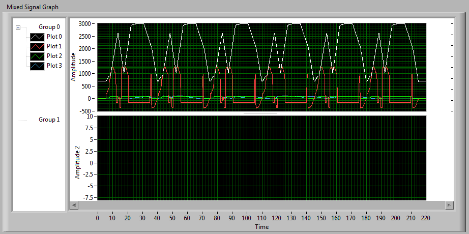
How do I return the scales on the Mixed graphic Signal?
LV 8.6.1f1
OK, so I look at the relatively new chart of MIXED SIGNALS to fix things that don't work on the regular chart (more precisely, the weird cursor behavior).
It seems I have a slider that spans four plots and reads an X 4 values of Y, that's what I want.
But I need ladders on both sides.
I tried to create the 2nd scale and the SIDES exchanged with her and got this:
There is no ladder on the right?
Or is it?
These graduations few are a clue.
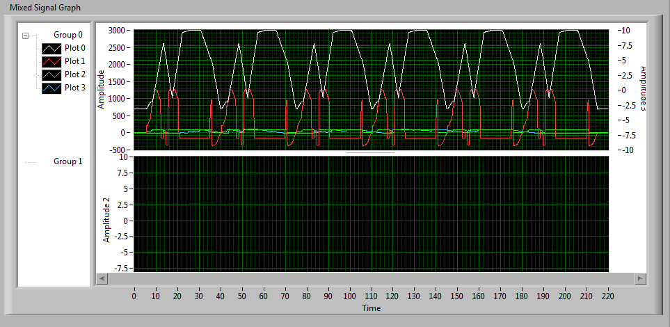
I so stretch the right side of the chart and guess what?
There is the scale:
In other words, the new graphic scale left anywhere on the screen, even if I resize the chart horizontally.
I can move the chart, the scale moves with him. I can re-size on the left, and the left scale shows the same effect.
It seems to me that graphic scales must be attached to the plot area.
This graph is a TAB control, maybe the problem is related to this error of LabVIEW.
Or am I missing something?
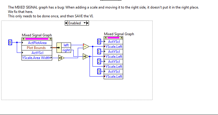
Here is the code I ended up with difficultytowork around this problem.
Mixed-Signal graph has ANOTHER problem where he completely forgets your assignments whose plots go on the scales, but that's another story.
In my case, I've already placed the scales on the sides left / right as needed. It's just that the right bottpm scale, really, really wants to be off to the right.
What I do here, it's fetching the LIMITS of PARCEL of land #0 (the top one).
I'm only interested in the left-right axis, I don't have a problem vertically.
Also, I extract the AREA of scale 0-WIDTH WIDE.
I then adjust the YSCALE. LEFT property of the four scales, place them where I want.
The two scales on the LEFT are the BOUNDARIES of the PARCEL. -LEFT (WIDTH + 1 ON THE SCALE)
The two scales on the RIGHT are to DRAW the BOUNDARIES. RIGHT + 1
The "+ 1" means there are a pixel between the scale graduation mark and the border of the chart itself. I think it's better.
Just run the VI once to run this code, then turn off the code section and save the VI. (You do not need to run it again unless something changes, he seems to remember where it is supposed to be).
Of course, if you resize the graphic, you will need to run the patch again.
-
I'm thinking GPR profiles which must have the scale placed along the top and side of the image borders. I need to crop the image, given that the existing software has its own scale that I can't use. I need to place the image on a neutral background cultivated have space to add text, such as the direction of the movement, magnetic north, information. Im going to try to * a copy of the image that I have for example. Although I want to learn how photoshop works I need to get this out of the way. You will also need to understand how to assemble the images since some reflection profiles are longer than what can show the soft ware GPR.

I would create a shape layer that contains your ranges. I make a separate scale for each side and have the scale longer that you need so you can use it with different images. Before you crop or resize, I bring in leaders and their reference of scale scale that you ever image before cropping. Then put the scales in a dynamic object and the harvest, ensuring that you remove cropped audited pixels. This will be crop your original image, but areas of scales that fall outside the area of culture will not be deleted, because they are in Society. Once crop you, if the image is a background image, change it to a normal layer by clicking on the lock icon in the layer panel. Now you can use the size of the canvas to add the amount of the borders you want around your image. You can create a United below your main image fill adjustment layer and choose what color you want the background to be. Then, you can move your scales where they should be. Use a mask for the scales if they are too long. Most of this can be implemented in action so that you don't have to manually do each step. The scales are fairly easy to do using the line shape tool. Just create a single line and duplicate many times you need divisions in your balance. One of the fixed lines at the beginning of the scale and the other at the end of the scale and select the layer with the line and use the distribution with the move tool function to space out the lines. Transform a part of the major subdivision to longer lines and add text. Here is an example of a scale, I did for my work:

-
I use a custom scale and the DAQ assistant to acquire data from a USB DAQ device. How can I display voltage gross values at the same time?
Thank you
David
Do not use the ladder custom, but read the raw data using the daq assistant and adapts the data later. Or the scale of the data using the inverse of the custom scale.
-
misfortunes of graphic intensity ramp 'Centre' of marker...
Hi all!
Like many people here, I am displaying the data on a graph of intensity. In my case, I use graphics cursors to move a XY stage and plot the data on the "Z". I do this very well using TWO regular graphs; one for the movement and other data. Combinging both at intensity is my next step. I can display data very well on a gray scale (so my sliders are apparent and are visible). Now, the part that has banging me my head against the wall...
The ramp attached example2 is directly from the examples. I just changed the color to a medium gray and I can drag the marker to marker Center up and down, effectively changing the 'contrast' If you want, to make the colors more visible lighter (lighter = a signal louder). I'm trying to do it programmatically in 3.
3 has some real data that I saved as DEFAULT. Once I "touched" the marker of the ramp, I lost the ability to change the ramp like example2. The parameters are the same. Using some examples, I found, that I managed to find a way to move the cursor from the center using a control (note range, so I get 1E-7, 7-2, etc.). But the color will not change when I change it with another control.
I want the exact configuration of the example 2, drag the marker and have the change of color range. The color of the center marker can / will be fixed, I tell myself that I can extract data Z MIN/MAX to set the initial position of the Center marker. I'll hide the ramp and just use a cursor to drag the Center marker up and down to move the "Central gray" up and down the ramp.
How to affect 3? Even manually sliding the marker does nothing now

Thank you!!
Steve
Hello Steven8R,
I played a bit with your screws for a while, hitting my head also, trying to understand why the other reacts differently. It turns out that it is a very simple solution.
In your 3 VI, while the VI is running, right-click on the graphic intensity 2 and then deselect the option "ignore the color Array. Then, you good to go.
As far as coding is concerned, I advise you to replace your reference variables VI with just nodes of property on the graph of the intensity. It will clean up your code and avoid any possible race condition for local Variables.
-
Satellite U400-112 - WoW problems and the image is not good
Hello!
My laptop is Satellite U400-112 and matching video Intel X 3100.
When I play in openGL, 3D graphics on minimum and the image quality are not good. The same situation with Direct3D even worse. I have a guess - the game not installed, I copied the folder with the game on another computer, maybe I need to reinstall? I installed the latest drivers for the video of the official website of Intel.
Maybe someone have the same problem and can help me to solve it.
Hello
This only happens on the world of Warcraft or in other games too?
I'm a bit confused because you have set the minimum graphics and then you wrote that the photo isn't good in my opinion that's normal as the photo isn't good, if you play on minimum graphics settings.
Maybe you can post a screenshot screen or something else.You also need to update DirectX version on your laptop that you can find on the Microsoft Web site.


Maybe you are looking for
-
LabVIEW has an automatic generator of document API?
Java's javadoc, which automatically generates the API documents. LabVIEW there equivalent or similar to that thing?
-
Atrix phone keyboard not working not during calls
I looked everywhere for a solution to this problem and wonder if anyone knows the sameproblem. During a call, when asked to enter my phone number, access code, etc., the keyboard disappears whenever I try to press any key. When I get a button to pres
-
Original title: update Acrobat. Hi, acrobat update fails after updating mandatory messagemreceived. What can I do?
-
You are trying to add H & R House, does not have enough resolution?
I am trying to load H & R Block home, comes back and says not enough resolution. What should I do?
-
I can't find a page where I can see comfortably, on my PC, the applications available for BB Curve 9360 on the BB site. (From p. \Apps home I get to a list of devices, where I find the curve, but when I click it, I sent again to the homepage!) Please