Graphical waveform Linestyle Bug?
Hello
I found that problems associated with the waveform diagrams and line styles in LV2016. If I change the line style of a multiplot for long dotted graph, the plot is changed for long dashed, but if new values are added, they will appear as short rushed. If there are other long plots dashed, they are modified short wiped out too. It happens with all styles (modern, classic, silver).
Everyone knows about these problems? Try again with the example below.
Niklas
The good news is that you are not crazy, LabVIEW 2016 's erratic behavior. In an attempt to discover what had happened and who was responsible, I wrote a little routine to read and set the Styles of plot line for graphic signals 2 consecutive values from 0 to 4 with a variable delay (so I could put 0, 1, 2, 3, 4, or, say, 2, 3, 4, 0, 1).
My initial code read the line Style, and then return. I could tell by looking at the plot that something wasn't right, and if I ran it again, I could see what values were used. For example, if I put 0, 1, 2, 3, 4, I had 0, 2, 2, 3, 4, while 1, 2, 3, 4, 0 gave me 2, 2, 3, 4, 0. Since I did the reading before writing it, I needed to run the code twice to see what did the writing, so I changed the code to read, write, read, as shown below:
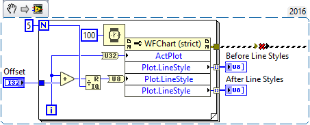
(The error shown above, dotted line was 'dug' NiklasN While loop to ensure that ran first).
Either incidentally, I added the delay time within the loop "just in case" LabVIEW need time to "adjust" the plots - I think it is probably indifferent...
To my surprise, the line Styles after were exactly what I expected - with an offset of 0, 0, 1, 2, 3, 4. However, if I immediately revived this code, the front line Styles (which should have been 0, 1, 2, 3, 4) were now 0, 2, 2, 3, 4, false! Also, if you look at the plots when you run the program several times without change to the Offset, you see Plot 1 change the appearance (probably when my 'put' loop runs) and then switch again as the numbers start to come there.
I just called Tech Support, made to this post, attached the code illustrating the problem (so they will have something to test), and I expect that they will confirm the Bug and drop off a CAR (report on the Corrective Action) to solve this problem. Thank you, NiklasN, to describe this issue.
Bob Schor
Tags: NI Software
Similar Questions
-
graphical waveform shortcut menu problems
Hello
We discovered a problem about shortcut menus on maps of waveform with our current installation of LV2009f2.
In the development environment ("IDE"), we have created a larger application. In the display section, we have several graphics (waveform), where the user can select the signal traced by the contextual menu (aka the context menu). When running the application in the IDE so good, the menus are displayed with all of the elements, we have defined.
So we have finished the debugging (so we thought) and created an executable. Then, we tested the executable on the same computer (the computer with IDE installed full). Everything if fine, context menus are shown as expected.
So, we got to the next step in the creation of an installation package (which resulted in a size of 0.99 GB btw...). LabVIEW makes no complaints and we have installed this app (using the Installer) on a clean computer. No problems so far, our application has started, everything was fine. But then we tried to change the display: NO POPUPS! Instead, we had error 1165 (problems with Insert on the Menu, "Can't find the menu"). What happens here? Anyone with a clue? Where is my menu (reference)?
OK, we had a second computer. Install this package of 0.99 GB too. From the app: just fine, except the missing context menus!
More information:
All computers are Windows XP, Service Pack, even. Context menus don't require no RTM file, so no missing additional files in the installation package. Menu references created by LabVIEW (IDE or RuntimeEngine [RTE]) on right mouse click on the control, so that there should be no problem with the benchmark missing or false. The values supplied to generate the menu are the same for the IDE and RTE, so no difference. The graphics are incorporated into a secondary, but still only had events for them, so we no problem. New: the reference for the menu is provided by LabVIEW (event "Activating the context menu", MenuRef), so it should be valid...
Sorry, no example. It is difficult to reproduce, when it only happens to RTÉ and only on computers, where no IDE is installed...
Tomorrow we will fill to the top of the VI for creating menu with a lot of debug message subVIs to check everything and everything is going on in there...
Hi Norbert and others.:
I found a solution for my problem (after a long session to create exe, deployment to a different computer, debugging and start all over again...).
In deployments executable the shortcut menu for the chart is missing (and is missing only here!). So I first test a menu empty on each activation of the menu and create a new menu if necessary. To do this, you will need to turn off (disable) "default DURATION of the context menus" during the VI containing the graphic.
A note more:
All other paid (menus VI other) are loaded correctly, all loaded screws work dynamically. It's only the RTM shortcut missing... (And the RTM file is set to 'always include' in the application Builder!)
-
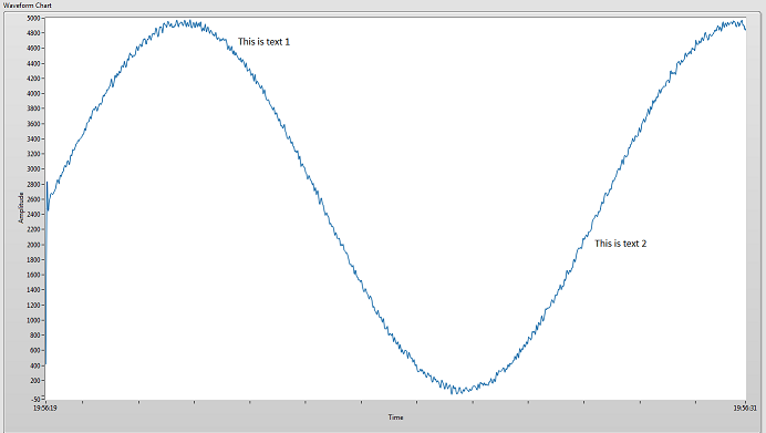
Draw text on the graphic waveform Plot
I need to understand how to draw text on a waveform graph during execution. This could be a text box, a picture of the text, a label and an additional plot with text... etc.
Yes, I know a graph would be better than this, but need to use a graphic for my application.
The graph is updated every second, and new data are added to the history of the ranking. (Which means that the chart bigger every second) So if I draw the text above or behind the table, I'll have to update their location every second. I'll have to use card to XY Coords in an event, (mousedown or mouseup) to place the text (or image of the text) in the field where the user clicked.
Step 1 to resolve this problem is to find first class, learn how to draw or text on the plot of the graph area.
Does anyone have ideas of how this could be accomplished, or some ideas of a sneaky work around to make this work?
Example:
Unfortunately, graphics (graphic and graphic waveform XY) have support Annotation and slider, exposed programmatically through properties, but the array of waveform is not.
What you could do is to place an indicator of 2D image that corresponds to the size of the chart above. Make the value of the image that you draw be transparent and just print the text with transparent backgrounds. However, I do not know the considerations on the performance of it - many times user interface elements, overlap (portions of even transparent) can cause problems of performance due to forcing redesigns... then again maybe a graph is always be redrawn in any case.
-
Envelope of a waveform's graph XY and graphic waveform need
The other threads here and here, I got great support from David and Thomas. Thank you all.

The envelope of the signal coming out as in the example of David is as a graph XY. But as in the example of Thomas, I need graphic waveform
in this format, so that i can find some of the edge values rising and falling in the waveform. Kindly suggest me how to handle this conversion. Thank you.
Mathan
-
Updated graphical waveform constantly with digital I/o
I'm new to Labview and I try a digital waveforms graph to update in real time after the analysis of the data of a digital acquisition of data from input to output. Is this possible or real time update can only be done with graphics?
Hello
Once, a very similar subject has been addressed in the forum of LabVIEW, where DFGray has responded to the following:
- You can use an XY graph generating X values yourself. This will ensure that you place the data exactly where you want it on the X axis. It's fast, but involves a cost of memory.
- You can use a chart of waveform with an entry of waveform instead of the cluster that you are using. Use the antiderivative of waveform to build instead of the bundler to make your waveform. Set the values of t0 on the appropriate values (negative work, as do the numbers - time is in seconds, using the primitive of timestamp to convert to DBL timestamp). Finally, you must set the graph of waveform to use the t0 values. Pop - up on the waveform graph and make sure that ignore the time information is not checked. Depending on your version of LabVIEW, you may need to appear on the chart or axis. When you uncheck ignore timestamp, you'll probably want to reformat the x-axis again. Waveform graph clears the data at each iteration, so you have to replot all your data every time. Just create an array of waveforms and keep to add. The t0s will waveforms in the right places. Yes, this can cause memory problems.
- Finally, you can use the waveform, that memory. Create waveforms as you did for the waveform chart and send them to the chart. He remembered what was sent to her from run to run. Make sure to set the length of the graphic history (pop up on the chart and select chart history length...) long enough to contain your data together. You can use a node property to retrieve the data at the end, if you wish.
Link to the original thread: http://forums.ni.com/ni/board/message?board.id=170&requireLogin=False&thread.id=102699
I hope that this solution solves the problem.
-
Graphical waveform reference conflict with table 2D?
Hello world
I have a problem (I hope so easy?) with the joint 2.vi Untiltted... I need to wire a reference (with the chart "MVC and Stim") to the Sub - VI X axis Curs table under so I get the x-axis positions the cursor over the chart MVC and Stim... When this chart is a 1 d array, it works fine (graph at the bottom should graphic data between the sliders)... But I change the MVC and graphic stem in a 2D array that draws multiple waveforms graph Ref do not connect to the Subvi?
Any suggestions? I'm on a tight schedule, and it's killing me slowly...
Kind regards
Jack
Hello
I do not have chekced your screws I did not LabVIEW on my pc at the moment. I hope that the code is LV 2010 or below. If this isn't the case, please send the code in a version compatible with LV 2010.
However, a few questions:
What is your Ref entry selected to include the data type? You create the reference control once again inside your sub vi when you changed from 1 d in table 2D graphics?
If Yes, suggest to the two qus, try removing the data type "include". This can cause problems in the future. Otherwise, you must re-create your sub vi entry ref control again.
one way is, just transfer the reference on the front of the vi that has graphics for the sub vi, use application of the nodes to get the name of the control and the reference in the Panel, check your "MVC" and "Stim" among the control names, get the control reference. This will save you the dotted arrows.
-
Graphical waveform of system update modes
I have two charts of waveform of the system receiving the same type of data (table 1), but they update differently when data reaches the "end" of the window. As you can see in the picture I attached, graphic moving updated constantly and the graph of force updates by creating extra space. Options update under graph properties are grayed out, so I do not have the option to change this. I looked through all the options and evertyhing seems to be the same. I also changed the data flow in the two graphs and behavior was the same thing with the dial-up data.
Is there something I forgot which is originally the graphs updated differently?
Free adjustment? It is available on the pop-up menu for the scale, but not on the property page. Strange?
Lynn
-
How to set the minimum value of a graphic waveform window?
I have a graphics property of waveform "minimum value", but the graph is not take the value that I gave him. He tends to zero, as well as the first two sliders that I put on the graph. The maximum value "will be" no problem, just like the second slider value. Everyone knows about this problem? Here's a screenshot...
Is there a reason why my chart does not have what I have to say?
Thank you
Sometimes you may have problems if the new minimum is higher than the maximum of old. Try to write at least again in another node in property after you set the maximum value
Without seeing your VI and some parameters of the example, (old max and min) new max and min, it is otherwise difficult to say.
-
How to implement graphical waveform cursor?
Hello
I used visa tools to make the data values .dat file... I used the table of waveform to graphically represent data of this file.i want to implement cursor in that you can help me how to do.
Kind regards
vijtin
Hi vijtin,
Replace your graph with a graph to a legend of cursor...
-
help understand the digital and graphical waveforms
Can someone explain to me how digital waveform working with NOR?
I did a channel physical and wired to a DAQMx create channel then I have it connected to a NSamp of 1Chan ereading Wfm DAQMx and then wired it to a graph of digital waveforms.
I put digital and graphical digital waveform playback in a loop.
When I run it, it seems to me only to get 1 sample on the graph per loop iteration.
The desired output is to add each digital sample as a function of delay which can connected and or scrolls in time to examine what is happening with the signals.
Where is my mistake?
My VI is attached.
Any help would be greatly appreciated!
Also another quick question, is there a 'comment' as a command / / c or ' in VB? Thank you.
Hi Henry,.
Thanks for the post! It seems that you are having problems with the acquisition and the graphic representation of digital data using DAQmx and LabVIEW. You are right that the type of program you have returned a single sample every loop iteration, because you make an acquisition without buffer, timed by the software. This means that the program reads a sample for each channel, whenever the DAQmx reading VI is called, which will depend on the speed of the software will run. In addition, when you view this data, the chart will only display data acquired for this iteration of the loop (that is, in this case, a single sample).
To accomplish what you want will take some extra work and overhead costs in the software, but you can essentially use a shift register and accumulate samples that your program runs. There is a practice done just VI to do this kind of thing with digital signals and is called DWDT Append Digital Signals.vi (this can be found in the palette of functions in respect of programming"Wfm Digital Waveform"). I created a small example which you should be able to run that does this. What actually happens is that the waveform is rewritten each time with new data added in addition to the data passed in. To be able to scroll back and view this data, I turned off automatic scale on the x axis (if it is enabled, it will constantly increase and tries to show all the data at the same time) and selected just a data window to display. In addition, I added a horizontal scroll bar to scroll through the review data.
And to answer your question about the code comments in LabVIEW, this can be done with a clear Structure of the diagram. You will find this structure in your palette of functions in respect of programming' Structures. Using this structure, you can select a part of your block diagram to disable and switch to the active state of wire through the or add different features that will run. Hope this helps and good luck!
-
How can I change the color of ground on a type of dynamic data graphic waveform?
I have several different plots on different graphics, and I want to set the colors different waveforms.
To view the waveforms on different graphs, I went to the dynamic and then divided data type wire
According to the number of channels I have.
I can set the background color of the chart with a property node and create sliders of different colors without problem
using the table of references that I created, so there's nothing wrong with my table of references or the property node.
As soon as I try and a box of thread in the plot color > control color to draw, I get error 1055 on the property node.
I was wondering if it was an error between keyboard and Chair, but now I think it's something more sinister.
The error box appears and cannot be fired left the update until I run TASKKILL on LabVIEW and terminate.
Any ideas on how to achieve my goal would be appreciated.
(LabVIEW 8.6)
My colleague has just acknowledged my problem and pointed me to the solution. It seems I need wiring in the value of "active conspiracy" of the loop each time and to ensure that this takes place before the update to track color.
I have attached a picture of a labour code. I intend to combine the whole lot to the node of a property with the active plot at the top so that it executes first.
Thank you for taking an interest Sheela
-
clear history graphic waveform dynamic data 1 d are used
I'm new to Labview and uses a waveform graph. To clear what I need to provide a table empty. I did it with scalars entered, but in this case, the entrance to the chart is a table 1 d of dynamic data beam. I can't understand how create a table empty appropriate table 1 d of dynamic data type to initialize the plot (the story line).
It seems that there should be a better (easier) way to erase the plot...
Thanks for all the ideas.
Hi rockybooth,.
Right click on the connector to the history of the property and select "create constant. You should get what you need.
It will be useful.
Mike
-
Multiple plots and graphic waveform database programming
Hello people, in my example attached vi, I have three plots of difree and a conspiracy of"base" on my table of waveform. I also ontrols to adjust the gain of these plots.
However, I also have controls on my front for each parcel of land that I can use to move the specific parcel to align with the field of"basic". I placed orders on my front but really confused on how to code to get this behavior. I would be grateful for any suggestion.
Thanks in advance.
Ines says:
If that's what you thought, you might want to expand more on your previous comment, as in "just add the controls with the values of Y.
You use the Add function to add your signal with your control. That's how apply you an offset.

And what is your problem, right-click on the caption on your chart and select-> visibility checkbox trace the visible elements. It's the easiest way to control what sites are actively presented.
-
How to view graphical waveform Excel data
I have a file .csv with 4 data column. I found something for another thread that allows me to display data from an Excel file in a table. I have a problem with the following:
(1) I need to display column data 4 but I can't seem to find a way to add other elements to the Invoke node so I'm stuck with power display only 2 columns of data.
(2) why can't take my output and put it in a table, and then view it on a waveform graph?
Please take a look at the attached VI. I took notes in the block diagram. When I try to join the Excel data to a chart, it indicates that the source type is a string, while the sink type is double. How can this be when the Excel file has only whole?
Help, please.
Thank you.
-
Move the Position graphic waveform zoom slider
Hello
I have 2 sliders in my chart of waveform and I wish I had the sliders move zoomed in the position of the chart when I zoomed in or out the graph. Some might tell me please how to do it. Thanks in advance
Concerning
Julien
There is an event that fires when one of the scales are modified. Set logic to reposition the sliders in the magnified needed area.
Mike...
Maybe you are looking for
-
Windows folder instead of the Officejet 6500 icon icon has more E710n in devices and printers
Can someone help me get the OfficeJet 6500 has more e710n printer to display correctly in devices and Printers icon? I have recently reinstalled Windows 8.1. However, when I installed my printer, the printer icon in devices and printers, I get a gen
-
Laptop HP 15 t-J000 - HP Recovery Manager question
Hi guys,. I have what should be a simple enough question. The laptop is as above - I am on Windows 8.1. My computer people at school asked me to reinstall windows 8 on my computer. It seems that the best way to do it is through HP Recovery Manager.
-
When the RTM exchange connector is released for Service manager 2012
Hello I installed the service manager 2012 GTR in the House... What is the Exchange Connector RTM being released, because it is only in the RC right now... Thank you Alex.
-
My XP laptop sees the officejet 6500 on the network but cannot print on it.
The diagnostic says HP drivers print program are not installed, but they are. My office windows 7 print very well.
-
Settings of brightness are reversed in Windows 7
Brightness settings under power options are inverted by setting to the left (dimmer) brightness setting lights up the screen and the gauge on the right setting that is supposed to make makes it brighter screen the screen inverter is possible in the r