How to measure an integrator integration time
Hi all
Sorry to bother you. Currently, I designed an analog Integrator who must be measured. First of all, I would like to apply a known signal and then measure the integration time. (I have a card PCI - 6251 DAQ for this).
To do this, I propose to build an "analog input sub - vi' to measure the output voltage of the Integrator. Meanwhile, use the meter to save time. When the output voltage of the Integrator has reached a specific level, I stop the integration action and stop the meter running. Finally, the integration time may be getting.
However, I have some problems to stop the meter when the voltage reaches the required level. Can I use a trigger to do? If so, how?
Can someone give me some tips or examples?
For you conveniet, I also did a conspiracy to explain the process, as shown below:
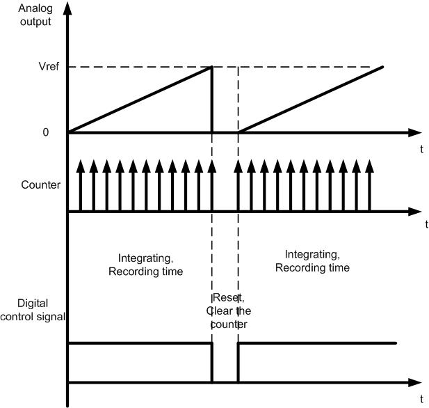
According to the plot, when the integration of process starts the meter must be started as well. After that, when the analog voltage reaches the required level (Vref), we must stop the meter running and return the stopped time. Meanwhile, a digital signal to stop integration as well.
Please give me some advice on how to make such a program. Especially on how to stop the meter when the voltage reaches the required level. In fact, it is my biggest problem. The second problem is the synchronization of the meter and the Integrator. I saw the example in Labview, and I'll try to test it. However, if you have any suggestions, please help me. Thank you in advance.
See you soon,.
Tingxuejh
Tags: NI Hardware
Similar Questions
-
How to measure my each operating time blocks
Hi, guys
I will measure my each main blocks, duration, are totally five large blocks in my final VI, the last four of them were in a while loop
Thank you
What exactly do you mean by "block"? Is this a Subvi, primitive LabVIEW, a piece of LabVIEW code?
You can use several functions of number of cycles. If you put your code in a flat sequence structure with Tick account in settings in the meantime, you can subtract the values from each other and to relative time of each piece of code.
Why are you worried about the execution time? Problems of particular clock? Most of the LabVIEW primitives will run so fast, you'll probably see no or very little change in the number of cycles before and after them.
Here is an example to show how measuring the execution time for a section of code.
-
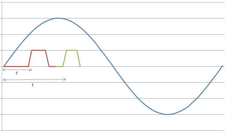
I have a sine wave of 50 Hz and a pulse of the signal on the same chart. The difference in phase between the two is between 0-90 degrees.
Now I need to calculate the time difference between (when the sinusoidal wave passes through zero volts) and (when the pulse increases). The frequency will remain about even for the two signals.
The request is for a three-phase generator. In simple terms, when the difference in time between the passage to zero of the sine wave and pulse increases increases, it means that the load on the generator has increased.
I am a novice user of LabView (version 9, 2009), maybe it's a very simple problem but I was pulling on my hair for the past few days and couldn't understand anything. Any help would be greatly appreciated. I use DAQ USB-6008 to measure these tensions and the impulse of the generator and a sensor
I have attached a jpg file (a graphic that I just did with excel to explain). The time 't' is what I'm trying to measure
See you soon
Zdzislaw
Awais.h,
For problems of this kind I recommend start writing the granular steps you would take to manually fix this problem. You can't say LabVIEW (or any programming language) If you can't succinctly describe the solution to your problem.
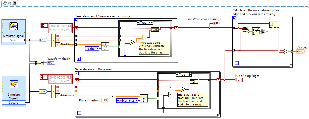
The I want to address this problem is to:
- find all the zero crossing points and edges on the rise
- for every rising edge find the difference between the timestamp and previous passage by zero
Here is an implementation of this algorithm LabVIEW:
-
Qosmio F50-126: how to activate the integrated graphics card?
Running Windows 7 on F50 - 126.
After checking my specs on the site Web of toshiba, here are the details on my graphics card: -.Manufacturer: NVIDIA;
type: NVIDIA; GeForce; 9700 M GTS supporting TurboCache; technology
memory: 512 MB dedicated VRAM (up to 1 791 MB of total available graphics memory using the TurboCache™ technology with 3 GB of system memory)
memory type: GDDR3 (800 MHz) video RAM (resp. RAM video and system memory combined)
connected bus: PCI Express 16 xI want to know if I can turn on my integrated graphics card. I know that clicking on powersave suppose to turn off my 9700 m and go to the integrated card, but the laptop did not want it actually disabled.
Like, watching a video or a game of battery the difference between "Powersafe" and "Balance" is not that much.The computer seems to work at full power.
Because I remember when I had Vista installed, the game and used trolling videoes. But on windows 7 it doesn't. Anyone know how to activate the integrated card?I have my computer updated completely and everthing... How d I do not know if my card is turned on or off?
Hi mate
I'm a bit confused of m.
Why?
Because you ask about activation and deactivation of the graphics card (integrated).First of all, there is ONLY a single graphic chip!
It s a GeForce 9700 M GTS graphics card.The graphics chip supports the 512 MB GDDR3 own (he dedicated video memory s) and it s is always available!
In addition, the chip supports shared system memory. It depends on the available main memory!
For example:
* With the help of Win 32 bit system *.System memory: * 2 GB *.
Dedicated video memory: 512 MB
Shared system memory: 767 MB (using 3 GB of RAM you 1279 MB)
TOTAL available graphics memory: 1279 MB (1791 using 3 GB of RAM)System memory: * 4 GB *.
Dedicated video memory: 512 MB
Shared system memory: 1279MB
TOTAL available graphics memory: 1791 MB* With the help of Win 64 bit system *.
System memory: * 2 GB *.
Dedicated video memory: 512 MB
Shared system memory: 767 MB
TOTAL available graphics memory: 1279MBSystem memory: * 4 GB *.
Dedicated video memory: 512 MB
Shared system memory: 1791
TOTAL available graphics memory: 2303As you can see the use of Win 64-bit and 4 GB of RAM would be better for the graphics card as the use of the file Win 32 bit with 4 GB of RAM
-
How to measure and mark the value of real-time data?
Hello
I need to measure and trace in time real RMS value of EMG power. I did a VI. But I don't know why it didn't work. Can someone help me please? My VI is set in 2013 and 2011 both version. An example of data is also attached. Thanks in advance.
Taslim. Reza says:
I tried RMS PtByPt VI. But it has not been wired because the source was table 1 d of double and double sink.
Well, ptbypt tools affect only one value at a time, so you must place them in a loop FOR. Here's how.
-
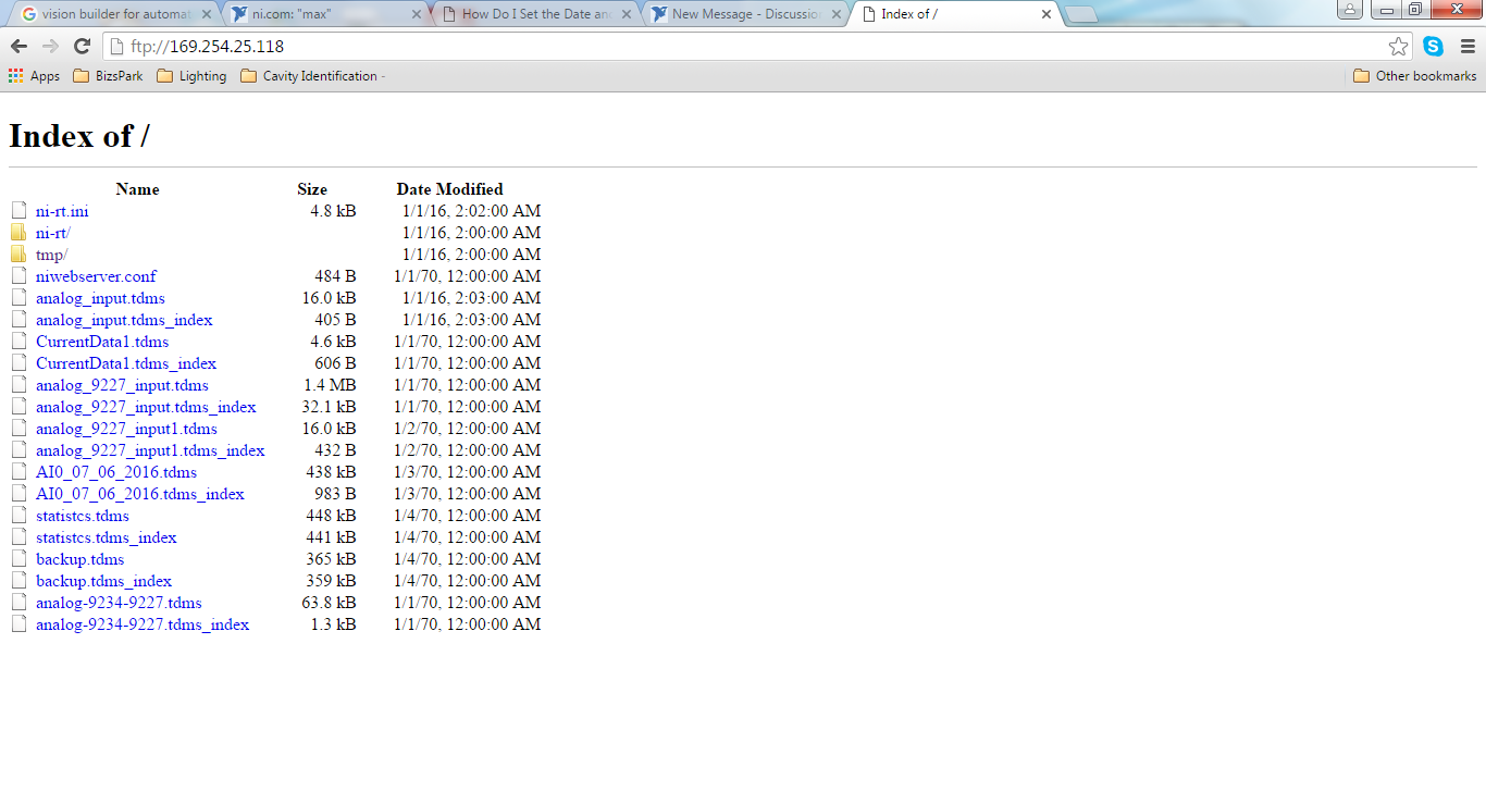
How to set the Date and time on a remote target in Measurement & Automation Explorer (MAX)?
Hello
I'm trying to follow the steps described in the following link:
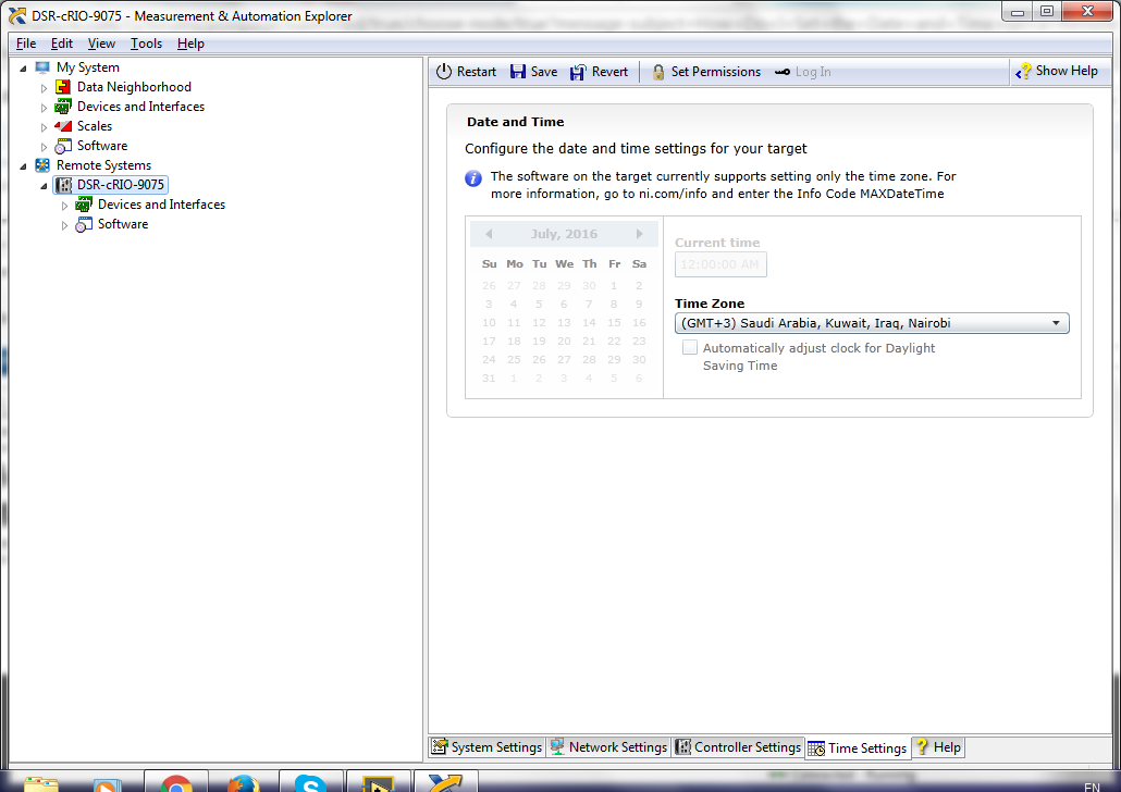
How to set the Date and time on a remote target in Measurement & Automation Explorer (MAX)?
It is said
The software on the target currently supports only the time zoneand deletes the old files?
I need set the date and time
and remove all the old unwanted files
the calendar was gray does not allow me to change the current date.
Anyone know how to change
Hi all!
According to this the below Knowledge Base article, Remote Configuration System Support must be installed on the target for time settings to change in MAX.
If you don't know what version of the system supported remote Configuration software that you have installed on your device target, it is likely that it is not yet installed. Add this software by clicking below your target to the MAX software option and selecting "Add/Remove Software". This is where you will install the System Configuration Remote Support software.
Please let us know if you have any questions!
-
How to measure how long a Boolean value is high with thick County?
I acquire the impulse response of a parallax Distance sensor, but I I don't know how to measure the number of features that this signal is high (the time of the input signal is high is proportional to the distance). I would like to reset the counter thickness when this signal is low. is this possible? Y at - it another option?
Thank you...
for (imstuck) wrote:
You will need to adjust some if you want an indicator of up-to-date at all times.
Here is a very minimalist version which updates the timer continuously while the switch is on and holds last value when the switch is off. Try it!

-
Update graph XY measurement at the same time.
Hello
I want to update chart XY measurement at the same time.
Normally, the graph is last updated after taking the reading.
I tried to make a chart that is updated at the same time, but it's not seems a correct value.
You please guide me.
Thank you very much...
Sorry, I can't know how many plots you have on the chart. Only one?
Here is a small example showing the gradual construction of a xy chart. Maybe you can adapt it to your problem.
-
How to measure high voltage (60-70 v) and current (75-80 a) using a DAQ PCI or USB DAQ
Hello
I work with a system that works on about 5kW. The output of the system voltage can go maximum up to 60-70 v and thus the corresponding current around 75-80 a. I have 10 these systems that I want to read one by one continuously for long periods.
I am designing the automated system best suited for this and looking for the best material that would be appropriate for this purpose. Looking for options, I found that an SCC - A10 attenuator may be used to get the tension down by a factor of 10. But I'm confused, if the high current will pose a problem and also how to measure this high current.
I need to measure the voltage and current at the same time. Please suggest what would be the most appropriate fitting for the same (preferably PCI or USB)
The hope of a quick response. Thanks and greetings
Reena Sharma
Facilitated learning
Reena says:
Hi all
There is good news that the idea of using a compact data acquisition has been accepted by the authorities of the society. I'll be very grateful, if you could suggest me with some hardware modules suitable for my application and how I can use them best.
Thank you very much
Reena
I was able to make a few suggestions, but do not have the time to understand your needs and the forums are not the best solution.
Your Local OR representitive actully gets paid to do this kind of thing. a google search suggests THAT LME is in Pasadena. Zack Collins would be the contact rep
-
How to create a graph in time real LabVIEW 6.1?
I am new to programming in LabVIEW (6.1). I wonder to create a LabVIEW interface that can operate the multimeter Keithley 6487, allowing us to apply a voltage and nth measures. With the measures that we have create a chart (V curve i) I find the XY graph, but it only allows to send all the measures at the same time (indexing) to generate the graph and not whenever we take the action so the graph build inn in real-time. I need to know how to create a chart or change the XY graph, so I can generate the i - V curve with each step we take in real time. Whenever we take the action and not once the program ends. Thanks in advance.
You must place the graphic inside the loop and the use of shift registers to accumulate the X and Y in the form of tables. I do not have 6.1 right now in the process of execution, but it would basically look like this:

Note that the above is for demonstration (the code is in fact a greedy loop). You can consider putting Scripture on file inside the loop. In this way, if the program crashes, you will not lose your data.
WARNING: Using table build as indicated above will result in continued growth of memory. If your program is running for a long time, this can become a problem. One thing you may need to watch must have a limit on the size of the array. I know there is an example of "Table of XY" comes with LabVIEW, and I'm sure that this is with 6.1. You should take a look at this example, which implements a fixed buffer for the data in the chart size. You should be able to use the VI "graphic buffer XY"directly in your code. "
-
How to measure the amount of traffic?
Hello ^ ^
In fact the question what I say, it's different from other issues that people are making inquires.
However, I want to know my question because there is no one who can teach me...
Old time, I was wondering how to measure traffic
In other words, I want to know measure 'capacity for fabric.
I can easily see the 'capacity' in the data sheet.
In the Dell 8024F datasheet, I found below a.

It has "fabric capacity up to 480Gbps.
I think that 480Gbps means the ability to traffic, right?
When we choose to switch or router, we always refer technical sheet.
As I said to you continuously, the idea of what I want is less than thing.
How do you know and how to measure my traffic?
Perhaps in order to measure capacity, there is a program or another method?
Thank you.
The ability of the fabric is the aggregate maximum speed of 24 ports. The 8024f has 24-port SFP + which are 10 GB. This means that the equation to be: 24 (ports) * 2 (duplex) * 10 (Gbps) = 480Gbps. This indicates that the switch is not blocking and can manage the total bandwidth of all ports.
The switch has a usage page you can view. The page provides the following information:

The network manager to manage open offers also the possibility to track the use of bandwidth capacity. Here is a link with more information on OMNM.
-
How can I calculate the total time in java?
Hello!
I need to calculate the total time!
For example I start time:
Format formatter1;
Date date1 = new Date();
formatter1 = new SimpleDateFormat("hh:mm:ss");
Dim startTime = formatter1.format (date1);
startTime = "14:20:40.
And I have finishing time:
Format formatter2;
Date2 date = new Date();
formatter2 = new SimpleDateFormat("hh:mm:ss");
String finishTime = formatter2.format (date2);
finishTime = '08:30:55;
Also, having calculated manually, I get the total time: '18:10:15.
How can I calculate the total time in java? (Using formatter1 and formatter2 I guess)
What I need is to print 'total 18:10:15 '.
Thank you!800512 wrote:
I did the following, but I think something's wrong here:I've defined before: Date date1 = new Date(); Date2 date = new Date();
And it should be exactly 5 seconds between them.I found the delta between date1 and date2:
Format formatter = new SimpleDateFormat("HH:mm:ss");
timeInMilliFromStart long = date1.getTime () - date2.getTime ();
Date date3 = new Date (timeInMilliFromStart);
String timeInSecFromStart = formatter.format (date3);and I still get
timeInSecFromStart = 02:00:05But it should be exactly 00:00:05.
What is a problem?
Because, as I said, a Date to measure a moment in time, not a period. So when you have 5000 ms, and you that transform a Date, this means that 5 seconds after the time, which equals 00:00:05.000 01/01/1970 GMT.
As I said, if you are not currently in GMT, then you must set the DateFormat GMT TZ. Right now, it's to show you the time in your TZ. If you have included the date in your SimpleDateFormat, you would see the 01/01/1970 or 31/12/1969, function that TZ you find.
Bottom line: you try to use these classes in a sense they are not intended for, and while you can get the results you want for a limited set of entries if you understand how these classes and how to work with it, it is a fragile approach and comes with all sorts of warnings warning.
-
How can implement you not with Tim Capsule and AirPort their simulation on the iMac?
Hello
How can implement you not with Time Capsule and AirPort their simulation on the iMac?
I don't know what you're asking.
AirPort Extreme is a wireless router.
A Time Capsule airport is an AirPort Extreme with a built-in hard drive for data storage.
An iMac is a Mac computer.
An iMac is not a wireless router, so he is unable to perform the functions of a wireless router.
-
How do I connect/install my time capsule airport to my new WiFi network so she just backup my Mac and not to extend my WiFi or want to be a WiFi hotspot
There is no way to connect a TC to a wifi network. It must be connected by ethernet to the main modem or to the router.
I don't understand what you're asking...
If you want that the backup more wireless computer... How the TC cannot work as Wifi hotspot... It's impossible.
-
Satellite 1800-814: how to measure the temperature of the processor?
I replaced the radiator component on my laptop as it freezes suddenly during the operation. Now everything seems to be better, but still a last question. How to measure the temperature of the processor?
Dominic displays only HDD temp and MBM profile for 1800-224 display cases and the cpu. But if I can use this profile? Any other ideas how to meausre CPU temp?
MBM shows me around 40 to 49 ° C for the cpu. Is this normal or too high just to run windows?
Thanks in advance
Greetings
Jens GriegerHello
See this http://forums.computers.toshiba-europe.com/forums/thread.jspa?threadID=5564&messageID=19417
Maybe the help!


Maybe you are looking for
-
Can't seem to download or update anything after the update to 9.3.5.
Hello I can't update or download apps after updating my iPhone 6 s more to 9.3.5. Anyone with the same problem? The AppStore says I have updates, but it is still locked to wait to update after click on "update all" or click on them individually.
-
Can I use a GPIB PCI instead has a HP 82350
Can I use a card NI PCI-GPIB IEEE 488.2 in instead of a map of 82350 HP. I want to configure a 5890 II to a PC running Windows 2000 with the Chemstation B02.01 software. Sorry - Posted two places.
-
How can I write the value of floats Unitronics vision230 PLC with modbus Ethernet
How can I write the value of type Float in unitronics PLC Vision230 modbus ethernet (Ethernet Master Query.vi MB) usinsg I read and write register 32 bits, for example, I want to write the value 23.45 2nd Add. MF. And registry MF is the 32-bit regist
-
I got a new router installed sky. No problem has worked until I removed the old router of "available networks", then even if the wireless connection shows excellent I can't on the internet. I used the instructions in the article 811259. AFTE, delet
-
Impossible Windows 7 update when connected to my WRT54G.
For some reason, the computers that are connected via cable or wireless through my WRT54G verse. #6 (the v1.02.8 firmware version) will not connect updates (Error Codes: code 80072EE2-Win7, Vista-80072EFD) especially BONES, anti-virus, malware update