HSDIO
Hello
I'm playing a .hws waveform using "niHSDIO write file named Waveform. Get this strange error message:
Asked throughout the wave is not valid because the number of samples is not an integer multiple of the increment of wavelength. »
Status code :-200400
I need help!
Raha
Hey Roxette,.
Stuffing the rest of the signal with additional zeros should allow you to produce a quantum waveform.
Keep me posted!
Tags: NI Software
Similar Questions
-
LabVIEW HSDIO active channels equivalent property in c#
Y at - it an equavalent c# of active channels LabVIEW HSDIO set/get property. I looked into the latest version of the HSDIO c# wrapper and I couldn't find the enum property nor the constant property for use with the method SetString().
raffythegreat wrote:
Y at - it an equavalent c# of active channels LabVIEW HSDIO set/get property. I looked into the latest version of the HSDIO c# wrapper and I couldn't find the enum property nor the constant property for use with the method SetString().
You'll have better luck asking in the forum hardware DIO.
I took the last envelope http://www.ni.com/product-documentation/52900/en/ and he did not see the method you are looking for.
-
I'm using LabVIEW 2010 and installed the drivers from device LV2010 and try to use the HSDIO functions, while setting the HSDIO function on the block diagram showing niajel.dll is missing, can someone help me fix this bug.
I tried to uninstall and install not able to set several times.
Hello. niajel.dll corresponds to the NOR-TClk, although NEITHER-HSDIO does not specifically use it. You use certain functions TClk?
Also, what other PXI device driver are installed on the system? Could you give a report on the MAX system?
-
How can I turn a channel in the SMU-6556 hsdio for material comparison mode?
Hello
I am developing a system with Labview2013, TestStand2013, and SMU-6556
The system diagram is:
SMU-6556 > - 12 channels - 3---> Dut1
Hardware compare mode:---3 channels---> Dut2
| - 3 channels---> Dut3
| - 3 channels---> Dut4
In TestStand, I have the following configuration:
1. in the "Setup" section I'm loading ~ 10 digital waveforms with 12 channels each in memory of SMU-6556.
2. in the section 'Hand', that I'm running in hardware compare mode each digital waveforms. (DWF1, DWF2,..., DWF10)
The system works well for test of 4 had.
Without loading a new wave form how can I enable/disable underwent?
For example, how can I configure to test only the dut1 and dut3?
HELO engfpe,
You can see the advanced, advanced attribute: hardware compare: bit Error Cumulative property and see if that will get your request.
Cumulative error Bits will tell you what mistakes HWC product channels even if the FIFO is full. In this way, you can at least know where to pass the ASE. If it fails and you would like more information, then you should always charge the waveform in order to get a manageable number of HWC error, but hope that helps at least. This feature was added in NOR-HSDIO 2.0, so make sure you have the latest driver.
-
HSDIO 6556 loses the lock on the external clock
Hello
I'm encountring a strange problem. I use my 6556 HSDIO to generate some model using and external clock (around 20 MHz and 50 ohms impedance). This clock is provided by an MCU and the entire application does not work well. However, when I tried to cool the MCU (up to-10 °) the HSDIO loses the lock and tries to re - lock again (the Red turned led active). When this happens, I can see a new phase shift between the data generated and the external clock, within the scope that is fatal for my application. L ' other, I inspected the data generated looking for a glitch or gigue appearing at low temperatures... Notice anything special... I tried to heat the MCU upward at 100 °, HSDIO does not lock...
What can I do? 6556 HSDIO is apparently too sensitive...
Mar1
Hi Mar1,
Datasheet public for the chip used in the States of SMU - overclocking 6556 a typical tolerance of jitter of 20 000 ppm, with minimum of 5,000 ppm. For a 20 MHz clock, this corresponds to 1 ns of jitter typical and 250 ps in the worst case. That being said, we cannot guarantee the specifications that are not included in the specifications NEITHER SMU-6555/6556 document because it is not updated with the production trial.
Best regards
-
OR PCI-6542: Creation of dynamic waveforms using the HSDIO library
Hello!
I have problems to understand how to create waveforms using the HSDIO library to run on a card PCI-6542. I need to create a program that activates a channel for 12.5 microseconds, waiting for a while (i.e. 100 samples) and activates another channel to 12.5 microseconds.
This program must be used in a Multielement ultrasound system.
Here the example of dynamic generation program that transforms the channels 0-2 on 1024 samples.
/************************************************************************
*
* Example program:
* DynamicGeneration.c
*
* Description:
* Generates a simple model on the specified channel.
*
* Pin connection information:
* None.
*
************************************************************************// * Includes * /.
#include "niHSDIO.h"./ * Sets * /.
#define WAVEFORM_SIZE 1024int main (void)
{
ViRsrc deviceID = 'Dev1 ';
ViConstString channelList = "0-2";
ViReal64 sampleClockRate = 50.0e6;
DataWidth ViInt32 = 4;ViUInt32 waveformDataU32 [WAVEFORM_SIZE];
ViConstString waveformName = "myWfm";
ViInt32 timeout = 10000; / * milliseconds * /.ViSession vi = VI_NULL;
Error ViStatus = VI_SUCCESS;
Bruno errDesc [1024];
ViInt32 i;/ * Initialize generation session * /.
checkErr (niHSDIO_InitGenerationSession)
Deviceid, VI_FALSE, VI_FALSE, VI_NULL, &vi));/ * Assign channels for dynamic generation * /.
checkErr (niHSDIO_AssignDynamicChannels (vi, channelList));/ * Set up the clock sample parameters * /.
checkErr (niHSDIO_ConfigureSampleClock)
VI, NIHSDIO_VAL_ON_BOARD_CLOCK_STR, sampleClockRate));/ * Query the data Width attribute * /.
checkErr (niHSDIO_GetAttributeViInt32)
VI, VI_NULL, NIHSDIO_ATTR_DATA_WIDTH, & dataWidth));
/ * Fill the waveform with ramp data * /.
< waveform_size;="">
{
waveformDataU32 [i] = i;
}checkErr (niHSDIO_WriteNamedWaveformU32)
VI, waveformName, WAVEFORM_SIZE, waveformDataU32));/ * Start the generation * /.
checkErr (niHSDIO_Initiate (vi));/ * Wait for all the generation * /.
checkErr (niHSDIO_WaitUntilDone (vi, timeout));Error:
If (error is VI_SUCCESS)
{
/ * Print result * /.
printf ("made without error. \n") ;
}
on the other
{
/ * Get the description of the error and print * /.
niHSDIO_GetError (vi, & error, sizeof (errDesc) /sizeof (petitioner), errDesc);printf ("\nError encountered\n===\n%s\n", errDesc);
}/ * log * /.
niHSDIO_close (vi);/ * prompt to go out (for the popup console windows) * /.
to continue...\n");
GetChar ();error return;
}Issues related to the:
How can I change the values in waveformDataU32 to create market reports (instead of just always on)?
How to select the channel waveformDataU32 is applied to the?
Thank you!
Zachary Geier
The waveformDataU32 table is an array of 32-bit integers. Each bit corresponds to a line on the device. On the first clock cycle, this program outputs:
0000 0000 0000 0000 0000 0000 0000 0000
Then it displays the following, changing at each clock Pulse:
0000 0000 0000 0000 0000 0000 0000 0001,
0000 0000 0000 0000 0000 0000 0000 0010,
...
and so on all the way up to 1023:
0000 0000 0000 0000 00000011 1111 1111
In the example that you include at the bottom, you set the least significant bit (LSB) to zero and one, actually only change one line on the output. To change all the lines, you must instead use 4 294 967 295 or 0xFFFFFFFF:
< waveform_size;="">

     < 200){="" if="" sample="" number="" is="" less="" than="">

          waveformDataU32 [i] = 0;     Disable channels 0-2

     }

     else {}

          waveformDataU32 [i] = 4 294 967 295;     Otherwise turn on all channels to 800 samples

     }

} -
HSDIO - deterministic written submission during the generation
Hello
I use a card HSDIO (PXI-6542) to control a device (DUT) with a predefined fixed length, waveform continuously running.
That maybe had TO actually benefit from the dynamic changes in digital signals according to the measurements on the INSTRUMENT itself.
At the moment I just pass off the coast of the ASE and map HSDIO, write the new waveform on the map, turn to ESA and the generation of digital signals.
Of course, this is not optimal and I would like to change the way signal 'live', while the DUT is running.
Just crush a waveform, whereas it is generated should not be working smoothly due to a condition of race as explained here: http://digital.ni.com/public.nsf/allkb/14CE41C9CB9F10A88625766A005CEE47
I think that I've found a workaround, but need a confirmation about this.
Instead of just a waveform, I could use 2 and select which is generated using a trigger.
The corresponding script might look like this:
script myScript

  Repeat forever

          If scriptTrigger0

            generate a waveform1

          on the other

            generate a waveform2

          end if

  end repeat
For example, the idea is to generate a waveform1.
Then according to that CSA should I calculates waveform2 and transfer it to the HSDIO map.
I think here is overwrite waveform2 with the data of the same size will not create any small problem because it is not currently used to generate signals.
After this using the trigger, I could start using waveform2. If I need additional adjustment of wave shape I could do this by editing waveform1, so it is not used for the generation and thus now alternating serves really what waveform.
Am I correct in that a waveform in memory but are not currently used can be replaced without causing glitch on an another waveform that is currently?
Kind regards
Baptist
Hello, Baptist,.
Yes, you are right. It is a method to dynamically change the waveforms on the fly that was already used in the past. If you waveform1 to generate and download waveform2 then it is idle, it will not affect the generation of waveform1. Then, triggering via scripttrigger to waveform2, then you can download the next waveform, you want to use for waveform1 without affecting the production of waveform2.
-
Where can I find NEITHER-HSDIO SMU 6556 LabWindows CVI examples?
Greetings!
I am looking for examples LabWindows CVI or a help file that shows the function or api calls to control the attributes of progrannable of the HSDIO SMU 6556/6555.
Ken Grohman
Hi Ken;
"' You can find examples for the NOR-HSDIO in the example LabWindows CVI Finder by clicking on help > NOR example Finder and navigate to the material input and output" Modular Instruments ' NOR-HSDIO; "" "" or you can search in Start "all programs" National Instruments "NOR-HSDIO ' examples.
http://zone.NI.com/reference/en-XX/help/370520J-01/HSDIO/using_ni_hsdio_in_labwindows_cvi/
Just make sure that when you installed the driver, you have also installed the Application Development Enviroment Support for LabWindows CVI, otherwise the examples will not be there.
Best regards;
Pedro Muñoz
-
Can I do compare material using hsdio during the generation and clock speed of CQI are different
Hello
my application needs to generate a digital stream to A clock frequency with width of bus (number of bits) very from 1 to 4 bits
IAE response will always be on the bit but with a B clock frequency.
1. can I use the advice hsdio hardware comparison mechanism.
2 If the answer is YES, there is any sample that can help me to get started.
Thanks in advance
Daniel Gabel
Hello
Yes, you can compare material with different rates of acquisition and generation. There are several examples that are provided with the NOR-HSDIO driver. There are some examples of physical comparison you would like to check.
Jon S
-
Timed HSDIO generation specific?
Hi all
I am trying to generate data series (ex: ascent) with HSDIO 40 MHz clock-FREQ (25 ns pro bits)
My problem is, I need to generate a 14-bit-data (350 ns pro data) in each T1 (user input), but I don't think that my generation is really accurate.
I tried to add the array of 'F' behind each my data without using a delay with the while loop, it works very well for us (mikrosec), late in the range give but I have a problem when I try to get the delay in the s range (sec.), because the samples cannot be more than 4 M (I use HSDIO 6544).
Then I tried to use while loop with 'wait (ms)' write a data, delay, write the following data. But this delay in while loop tour, check with 'number of cycles' to measure the generation time, don't give me total constant time to generate data from 256. Should I use a loop timed for this? gives better control of calendar to write the data?
Oh yes, I need to write my datas in the SP range ~ s (from the user).
Kind regards
Yan.
Hi Mystogan,
why Don t you use a trigger signals to trigger your build.
If you want to generate a signal series based on incoming events, I think it is the way to go.
The HSDIO driver also has configurable delays for many of the relaxation/timing parameters.
Marco Brauner NIG.
-
Program vi to turn the lines Testpanels HSDIO
Hello everyone,
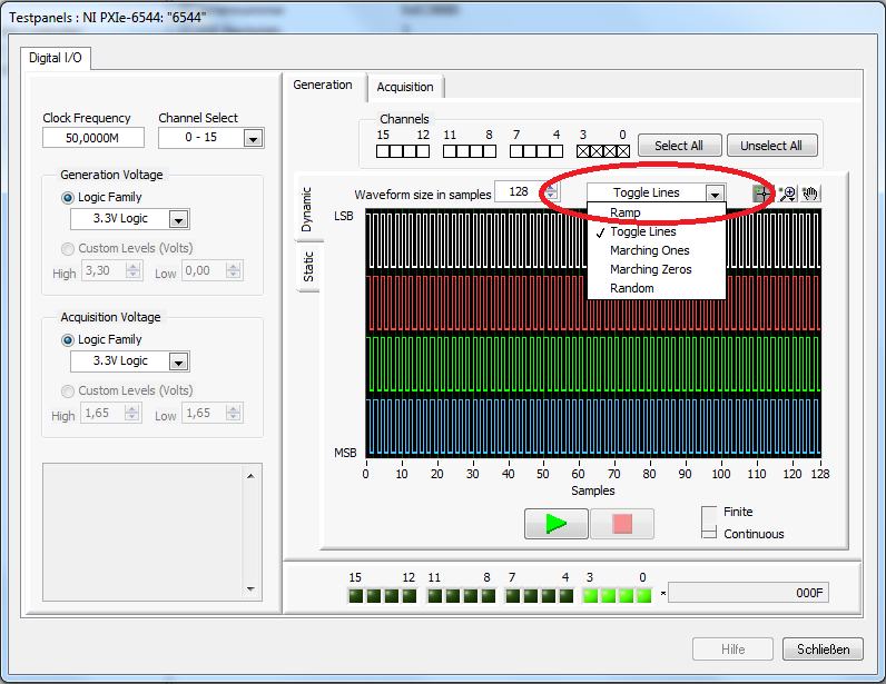
I have a question about HSDIO testpanels in MAX. There is an option to MAX to generate the data in various forms of digital data:
RAMP / TOGGLE LINES / THOSE WORKS / MARKET ZEROS / RANDOM.
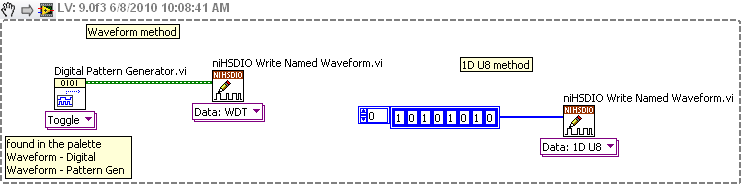
And most of the examples using HSDIO generate data using the method of the RAMP. I tried to look but I couldn't find other methods of data generation. I really need the program to generate the data with the method of the LINES of the ROCKER. Have tried to use the block express gen, but does not help me either. In my view, it should not be a complex built in the program, but somehow I don't see what I would do to generate this signal. I need two channels to generate the same signals as in the picture above.
I tried to build the ramp and a channel that connects with another a channel not used, but the voltage has dropped and so I don't want to use this method. Later, I may add delay to a channel, but I think I can get something of an example of NOR (dynamic generation with a delay of data).
Kind regards
Yan.
Hi Yan,
To get the clock frequency of 1/4 on two channels, it would look like this:
00
00
11
11
00
00
11
11
You oversample data and then you get two channels with frequency of output 1/4 clock rate.
-
HSDIO trigger for the transmitted waveform record
I use a card OR-6552 (actually this system eventually will use 7, so I'll try to get my head wrapped around the trigger events).
I use dynamic generation to generate a binary pattern on the pins 0-15.
I'm tracking the trigger from start to RTSI6.
I use a software trigger.
On the side of the reading, I use a dynamic Acquisition. The start trigger is triggered off the coast of RTSI6.
Everything works exactly as it is supposed to. I get the binary model, BUT
The read function is advanced clock EXACTLY 50 cycles. So, I get a '0' reading the lines of channel for 50 cycles before the binary sequence appears in my wave of reading.
I suspected that it has anything to do with the outbreak of the reference, so I tried to define the source of command reference for RTSI6 also, with delay sample 0, and I get a timeout.
I'm so close, but I would like to know why I'm getting a pre-roll buffer 50 cycle even if I did not specify...
-Mike
CCITest,
If you are looking to synchronize several 6552 juries, you will want to use TCLK. NEITHER TCLK is the synchronization scheme products Memory Core (SMC)-based and integrated with National Instruments synchronization. More information about the details behind this technology can be found in the help HSDIO document (start > programs > National Instruments > NOR-HSDIO > Documentation > NI Digital Waveform Generator-Analyzer Help). Inside of this help document, a good starting point is the title of programming > references > NOR-TClk synchronization help > preview OR-TClk.
NOR-TClk will allow you to start several cards at the same time. Leave your post I don't know if you are using a card PCI-6552 or PXI-6552 module, however when you use a version PCI RTSI cable allows up to 5 tips be connected. Using PXI, you can fill the frame and synchronize your 7 boards. There are several examples that show how to use NOR-TClk. These examples can be found under start > programs > National Instruments > NOR-HSDIO > example. Then choose your preferred language and select synchronization.llb or the sync folder.
-
Hello
I have these noticed that a newer version of HSDIO is available for download, so in some time I decided that would 'hurt' to install the latest version (ver1.74 upgrade). Once installed my SMU-1073 appeared in MAX and my card 6541, however the I had no control over the 6541. When I clicked on the self test it failed and threw an error when I tried to use the test Panel.
I tried a "repair installation" just in case, but there was no difference. For a finish I had to uninstall and reinstal version 1.74.
Anyone else seen similar issues?
I am running LV 2010.0.1 (32-bit) on a windows 7 x 64 machine.
Hello once again!
Question has not been resolved. We had an engineer OR visit today and managed to recover some of his time. It seems that the problem is related to the parameters OR charger.
Looking at the charger OR on my system it has been listed as "stopped".
It seems that the default settings are not "Act" If the service is not responding (maybe other things to start up or otherwise are bringing to fail.)
It was recommended to change it to "Restart the Service" and things seem to have improved.
Rgds,
CSV
-
Hi all
Are there examples of the HSDIO being programmed with DAQmx library card? I want to be able to use DAQmx and HSDIO libraries and impossible to find examples of DAQmx for me to operate against.
Thanks for any help and examples!
Manesh
Hi Manesh,
This is the case with the 6541 so. It is compatible with the HSDIO API, but not DAQmx.
-
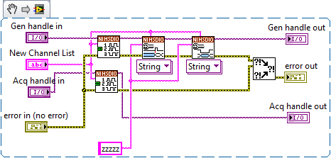
Dynamically change the Ni HSDIO channels
I am currently using a PXI-6552 module to generate and acquire I2C signals simultaneously. I would like to know if it is possible (and how I would go to this topic) to dynamic change channels. My goal is just to pass the two references of NOR-HSDIO (purple variables) to a new slot - VI that I create from a different set of 5 channels 5 channels. For example:
Pseudocode:
PXI sessions initialize;
for (i = 0; i< 10;="">
{
Set the channels 0-5;
Generate and acquire;
Stop the acquisition;
Set channels to 6-10;
Generate and acquire;
Stop the acquisition;
Set channels to 11-15;
Generate and acquire;
Stop the acquisition;
}
close the sessions of PXI;
Basically, I need the fastest way for acquisition channels without having to initialize and close sessions each time.
I am currently using the HWC downloaded the example .zip from here: http://www.ni.com/example/31200/en/. (I've also attached the two that are necessary for my problem).
Init HWC Device.vi: (also attached)
Performance Device.vi HWC: (also attached)
I may need on the screws are Assign dynamic channels, Configure Idle State and initial configuration. However, I don't know if those are the only ones. If it's possible, can I close the original channels and then assign more? Or re-call "Dynamic Assign Channels" automatically disables all channels not assigned? Etc.
The important things to note: I'll put 5 channels at once - for both acquisition AND generation. I need to close the channels and proceed with 5 different channels - for both acquisition AND generation. All channels must be on the State of the 'z' to high impedance permanently.
If you need further information, please let me know! Thanks in advance for any suggestions and assistance.
By trial and error, I was able to find a way to do this:
-
How to generate signals using NI - HSDIO.
Hello
I need to create two signals different pulse square. I don't know how to set their frequencies, number of cycles and FRP using NOR-HSDIO.
Thank you!!
You must create a set of data to send to the HSDIO. It only builds what you send to it. Suppose you want to produce a square on one channel wave. Implement the HSDIO for right channel, trigger, timing, etc. Look at the function HSDIO write nominated Waveform. It says name of waveform, but you can use the polymorphic selector (the area under the function) to select other types of data outside of the waveform, i.e. a table 1 d of numeric (U32, U16, etc.). You must create an arry of data that would be akin to a square wave. Or you could use the input waveform and create a square wave.
The simplest is the waveform because Labview waveform generator functions available. See the image below. If you want to use table 1 d, construct you a table or alternation of 1 and 0 to produce a square wave. The image below is only a partial code. Need to add the rest of the installation HSDIO functions.
Maybe you are looking for
-
iOS 9.3 will not load because you are no longer connected to the internet
iOS 9.3 will not load because you are no longer connected to the internet on my phone 5
-
Journal print - Photosmart 7520 fax auto shut-off
As a topic, how to prevent faxes print log after each shipment? A previous answer for another model is not applicable for the 7520. TIA.
-
I just bought my Fuze yesterday (and it's the first real MP3 player I used other than a cheapie)-I rebooted it and responsible for some of the songs, and they play... when I can get to it. My problem is, I can scroll left and right but not up and do
-
Hi, I have re-installed Windows Vista on my laptop (dell insparon) 1525 and now my wireless does not work. ive tried re installing driver, but it says operating system not supported. I used the disc that came with the computer of the re install and I
-
I'm trying to get a playback loop by using the multimedia rendering engine
As part of the MP3 standard, there is a gap of millisecond 20 at the beginning of each file. so when I have an MP3 in a loop there is a sudden gap when the queue restarts. So my question is... Is there a way to tell the media rendering engine a loop