ID: 5124
My client is running signature value S74 on a virtual machines with idsmon 1.2.3 2.2 and 3.1 version sensors (5).
VEI receives an event for IIS CGI Double decoding ID: 5124 Sub ID: 1. While they inspected the content buffer for the event, the following string is observed. (http://x/x/x/x%252Fxxx.jsp)
My question is this:
The buffer contains a % 252F and that triggered the event
The signature under seem to 2F as an exact match?
or
Can there be spaces and characters in the middle of the 2 and F (as are in the buffer [52]) and always raise the event.
The signing triggered correctly?
The signature is looking for a model of literal "[%] [2], [5] [2] [Ff]" in the URI. By the regular expression, no spaces or other characters can be the sequence. Starting from the observed chain, the signature appears fired correctly. While we know quite benign triggers, it may be possible that this is legitimate traffic.
Tags: Cisco Security
Similar Questions
-
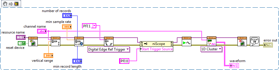
The NI PCI-5124 scope with 2 triggers
Hello
I would like to ask about the trigger for starting and reference with PCI-5124.
I found a sample VI on the following link, but it does not work as I expected.
http://zone.NI.com/DevZone/CDA/EPD/p/ID/2998
VI 'start_and_reference_trigger.vi' can detect the outbreak starting and reference in my system, and they begin data acquisition.
He starts data acquisition when both start and reference triggers are entered.
However, what I would do is:
1. sampling at 200 MHz with a 1500 with a single channel record length.
2. receive the signal to start (i.e. 50 Hz)
3 receive the reference signal (i.e. 50 kHz)
4. for each trigger reference, I would like to acquire the data, i.e. data of 1500 for each 100 trigger acquisition reference (not with the combination with the shutter release to start)
Start trigger: _|^|_________________________________________
Ref trigger:______|__|__|__|__|__|__|__|__|__|__|__|__|__|__|____
^ ^ ^ ^ ^ ^ ^ ^ ^ ^ ^ ^ ^ ^
hours of relaxing I want to acquire
Trigger channels I use are:
Start the trigger: PFI 0
Trigger for Ref: PFI 1
With the sample VI 'start_and... '. ", I found that it acquires when the two begin and trigger reference comes and data collection was only after the release of a single reference.
I hope my explanation is understandable and I can have a solution soon.
Hi Tom,
This example configures a trigger starting and reference, but only for a single record. It is inside a loop, so it will continue to require a trigger start and each record. According to your description of the problem, you want to make an acquisition standard multi-record of 100 records, but you want to implement a trigger to start at the beginning of the acquisition. "' To do this, you can simply open the example of shipping"niScope EX Multi Record.vi"found in the example Finder LabVIEW or by browsing in your Start menu programs" National Instruments "NOR-SCOPE ' example. You need to add the property node to define your Trigger source begin to be PFI 0, but other than that, it should work fine. I have advanced and created a simplified with the trigger Start implemented, attached below. I hope this helps!
-
Hi all
play with a digitizer PXI-5124 in a case of PXI1042Q with a PXI8110 controller that runs labview 2012 (latest updates) with the latest version of the driver NIScope.
I put in place an acquisition of off-delay (by assigning the triggering delay, for example 20us) which works very well (I can tell by the signal I get delay control works correctly), but the data returned in the info wfm cluster (using the 2D version of niScope I16 Fetch) does not have this delay.
Description of the relativeInitialX within this cluster indicator indicates "is the time in seconds between the trigger and the first sample in the acquired waveform" but its never to return something around 1E-9 independent of trigger delay. Surely the relative initial x should reflect the triggering delay?
I'm doing something wrong?
Thanks for your help!
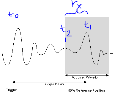
So, I made a screenshot of the image in the section "Trigger Delay" link I sent you.
Meaning of the symbol:
T0 = original moment of relaxation
T1 = time to trigger used in the acquired record (t1 = t0 + TriggerDelay)
T2 = time of first sample in the record of the acquis.
RX = relativeInitialX = t1 - t2
Response to previous reviews
«I understand what you're saying - so basically, if I want to know the delay of my trigger for the first sample in the record, I just add my delay time value to the relativeInitialX.»
- Close, the delay of the original trigger (t0), for the first sample in the record (t2), would actually be TriggerDelay-relativeInitialX
«.. . Nowhere does graphically describe where is the relative value of initialX real. »
- Right, relativeInitialX is not a timestamp, so it is not a place on the timeline, it is the difference between two timestamps (t1 and t2 above), where the relativeInitialX name.
"The trigger"record"is the straight line in the Middle, so expect relative to - 1/2 initialX record length?
- Almost correct, because the reference trigger is relativeInitialX to the position of 50%, will be the time in seconds for 1/2 the record length. (i.e. If the registration has been long relativeInitialX, 2s = 1 s). RelativeInitialX will always be the delta time between the trigger (t1) and the first sample returned in the record (t2).
- For example using the picture above: If t0 is 10 sec, Trigger Delay = 3 sec, SampleRate = 1 kHz, = 1000 record size. This means that t1 = 13 s. Our record is long of 1s (1000 points to 1 DC between each = 1 s), if t2 = 12.5 sec. If away from all these moments are absolute time, as the timestamps. So relativeInitialX = t1 - t2 is 13-12, 5 = 0.5 sec.
- As a side note, the reference position should not be 50%, you can configure to between 0-100%.
Time not yet discussed record attributes
I don't want to make you more confused, but there is another useful attribute in the waveform info that we've not yet discussed and its AbsoluteInitialX. Starting from the NOR-SCOPE help file:"absoluteInitialX is the timestamp of the first sample of recoveries in seconds..." "So, using the above image, absoluteInitialX = t2.
I hope this helps. If a part is still not clear, let me know.
-Nathan
-
Hello
I would really appreciate if you could give me some advice on my digitizer NI 5124 acquisition trigger.
Basically, what I'm trying to do is this:
1 make an acquisition triggered (using an analog edge trigger). My signal goes in channel 1, the trigger (TTL) goes to the input external trigger. It works beautifully.
2 make a multi-record acquisition. It works very well also. The result after "niScope Binary.vi MultiFetch" is a 2d array, which I convert it to image.
3. the problem is that I want to start the acquisition in question from my 'image' (of my acquisition multi-record) using another trigger (to about 2 Hz) (my first record should be synchronized with my external trigger).
I am quite sure that this is not an unknown problem, but unfortunately, I am not "smart" enough for me the tri...
Thank you very much.
Adrian
Hi Adrien,.
Thanks for the clarification. -What is your fastest trigger (the reference trigger) synchronous trigger slower that you want to start your purchase on? In the example that I posted on the other post on the forum, you can see that a normal reference trigger is configured, but I have also included a property node to set the Start command source to be PFI 0. The scanner will not arm themselves and begin to acquire samples before trigger until the trigger is detected on the PFI 0 line. It would be the slow, second trigger in your case. The scanner will not start acquire records the signal faster until this slowdown trigger occurs. Of course, if two trigger signals are perfectly aligned, you may miss the first edge (line 1) since the digitizer was just being armed, but could you explain such a situation by adjusting the trigger to occur on a bottom-up/top-down edge and take more or less before instant release of samples.
Is there something else in particular about the other post or the example I gave, I can help you better explain?
Kind regards
-
5922 5124 fuse, spec of 5V @ 9 mini DIN at THE poles of output
Cross posted, this forum seems more active...
I can't find the specifications of the + 5V output current nominal (pin 1 to Pin 2 GND) on the scope of the mini-DIN connector cards (5922/5124) 9-pole
Hi Hendrik,
According to internal documents, the
OR PXI-5922 - National Instruments
http://sine.NI.com/NIPs/CDs/view/p/lang/en/NID/201603Order number 779153-01
use a 1.1 polyfuse for to THE + 5V (fused) pin.
The
OR PXI-5124 - National Instruments
http://sine.NI.com/NIPs/CDs/view/p/lang/en/NID/14231Number of the Oder 778757-01/02/03/04
Use the same fuse with 1.1 next.
Best regards, Stephan
-
How to determine the amount of memory on the PXI-5124
Can I determine the amount of memory on the PXI-5124 visually? I don't see a reference as 778757-02 on the map.
Hello axiomtest,
There are two stickers on the back of the card (including one with a barcode) and the other without. The part number is that without the bar code and from there, you can search your memory option on our Web site. If there is no sticker on the card, which looks like yours have been removed, then use this example of community in LabVIEW to determine the size of your card.
Kind regards
-
OR-scope disconnect routing BUG?
I use a synchronized with a 6652 and a 5124 5922.
runs the task I want to tried get relaxation from start to PFI0 or PFI1, routing, however NO PFI0 or PFI1 does not seem to disconnect the routing.
I have attached a simple vi for test. An additional cable to monitor the PFI mini DIN output to a scope is necessary

- Choose the 5922, run the vi.
- Read success (some samples are taken)
- Press the PFI0 button (START TRIGGER is routed to PFI0)
- to read (see the trigger on the PFI0 pulse)
- disable the PFI0 button (none is routed to PFI0)
- Hit read (uups, always trigger pulse here)
Is this a BUG or how to disconnect the starting of the PFI trigger signal without losing my sync?
Henrik,
I don't see the problem, your code does not work as you described, but how you try to unplugged the lines wrong REIT. In the niScope export Signal documentation, it says "unprogram a specific line on a device, call this VI with the signal is no longer you want to export, and then set it to any Terminal output .»
In your code, you write you write Trigger start to PFI0, which allows the export of the trigger PFI0 to start. To cancel it, you must write Start Trigger None (no PFI0). You write 'none' to the wrong entrance of the vi.
Attached is a copy of your VI it properly deactivated the IFP routing.
I hope this helps!
Nathan
-
PXI communication problem of NOR
Hello
I use the chassis NI PXI-1042 q with NI PXI-8196 embedded controller, I couldn't contact my NI PXI PCB (NI PXI-5124, NI PXI-4472 etc.)
Currently, I installed NI LabVIEW 2010, NI MAX 4.3 and WINDOWS XP operating system
Concerning
Raj Kumar S
Have you tried to go down and retrieve the PXI cards?
Another tip:
The NI PXI-8196 RT is a RT controller where you can download and run your application in real-time. In other words, you have to develop your application in a Windows operating system and download your app in 8196 via Ethernet.
You should see your PXI as a big cRIO with PXI cards.
You can double bot your PXI (Windows or RealTimeOS). This link might help you understand your hard specifications:
http://www.NI.com/PDF/products/us/2005_5483_501_101.PDF
ARO
Vincent
-
measurement of the delay time to fall on the rise
I use the PXI-5124 digitizer and development of codes in C++ to measure the time between the 2 channels. I put the trigger on channel 0. I need to measure the delay time of CH0 AMOUNTING to CH1 RISING, CH0 AMOUNTING to CH1 TOMBANT, CH0 FALLING RISING, CH0 TOMBANT to CH1 TOMBANT CH1.
I encountered the following problems.
1. when I tried inverted signals using the niScope_AddWaveformProcessing() function, I had to call NISCOPE_VAL_ARRAY_GAIN twice. Second call with gin = 1. Otherwise, the waveforms being feteched were not reversed. This happened to both channels. Here is the code I use.
niScope_SetAttributeViReal64(session,"1",NISCOPE_ATTR_MEAS_ARRAY_GAIN,-1));
niScope_AddWaveformProcessing (session, "1", NISCOPE_VAL_ARRAY_GAIN));
niScope_SetAttributeViReal64 (session, "1", NISCOPE_ATTR_MEAS_ARRAY_GAIN, 1));
niScope_AddWaveformProcessing(session,"1",NISCOPE_VAL_ARRAY_GAIN));niScope_FetchArrayMeasurement (session, "1", timeout, [channel] NISCOPE_VAL_ARRAY_GAIN, actualRecordLength, wave [channel], & wfmInfoPtr));
Code that write the [vague] in a control file
2. even if with above method to obtain a code reversed, I can't get a correct results of CH0 FALLS of CH1 RISING. In addition, I don't know if the other delays are correct or not.
Please see the attachment for the functions dgz_measure() and NI_DGZ codes::meas_delaytime();
Other scalar measures seem ok. I also tried the FFT, it should be ok too.
What I've done wrong? Is there any sample code for the delay time?
I checked the AdvancedMeasurementLibrary already.
Hi, Jean Louis,.
It works fine now. He needs to call niScope_FetchArrayMeasurement after you set the attribute. There is no need to call niScope_AddwavefromProcessing. The niScope_FetchArrayMeasurement and niScope_AddwavefromProcessing will be peform the operation. So if I called two of them, the operation will be twice. Here is the code that works.
niScope_SetAttributeViReal64(session,"1",NISCOPE_ATTR_MEAS_ARRAY_GAIN,-1));
niScope_FetchArrayMeasurement (session, "1", timeout, [channel] NISCOPE_VAL_ARRAY_GAIN, actualRecordLength, wave [channel], & wfmInfoPtr));Thank you very much!
-
hardware error internal-234101
Hello
Executing automatic calibration on my PXI-5124, I met the error message attached with 234101 error code.
I searched the Web site of NOR and found this link: http://digital.ni.com/public.nsf/allkb/38BABFA0A6580C2A86257027007181FA
It solves the problem for a slightly different error and I thought it might be useful.
So I upgraded my NOR-Scope to 3.4.1 since version 2.5, but it did not help.
Anyone can comment on by this hardware error?
Hi Eren,
Looks like it's a legitimate hardware failure and you should definitely get referred back to Committee.
You'll want to go to ni.com/ask and create a service request to talk to an engineer. Tell them that you have already checked that it is most likely a RMA number with another engineer of Applications on the forums. In addition, mention that you would like to try to get an advance replacement and they can check to see if it would be available to you. I'm sorry to hear that this was happening. I hope we get it taken care of for you as soon as possible.
Chris W
-
Get the value of the frequency of the power spectrum
I'm rather new to LabView and want to measure the frequency of the peak in a spectrum of power of a real signal. In addition, I want this value of frequency and amplitude to save to a file. Right now I am able to trace a spectrum of power using an express VI, which gives me the correct frequency value in the graph.
However, I'm not able to extract the value of the frequency with different screws, I found in LabView after browsing through the various discussions in this forum. Can someone tell me please in the right direction? I use a digitizer NI PXI-5124 to record the signal in a rack of NOR.
If it is the dominant frequency you are looking for you can use the vi extracted a single signal. You can also change this vi to include the details of the search if it isn't the dominant frequency, I have not included it in my example, but you can check it in the help file.
Ian
-
Continuous acquisition and synchronization of two scanners
Hello!
I use two scanners high-speed NI PXI-5124. I'm running a continuous acquisition as in the attached example. I have two questions:
(1) is it possible to make life-long using another source of trigger software INSTEAD?
(2) depending on the answer to the first question - how to synchronize two scanners? In the attached example scanners have the same source of the clock, and they receive the same synchronization synchronization signal so the sampling rates are the same, but there is a lag of random phase each time I start the acquisition.
Thank you!
IVA
Hello, Mateusz!
I just apply the idea in the examples, as well as ideas from here, and here is the solution that works.
Thank you!
IVA
-
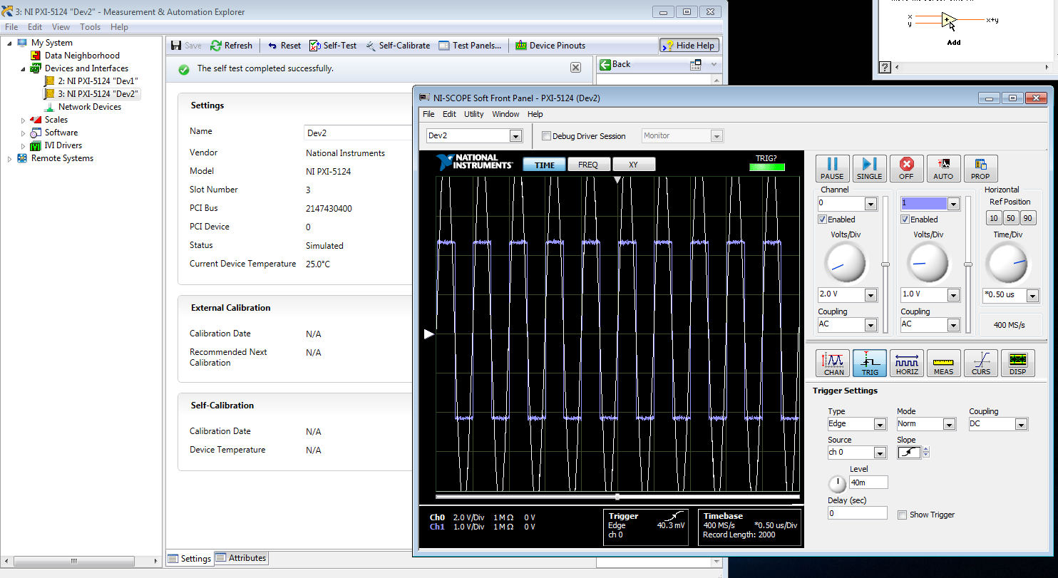
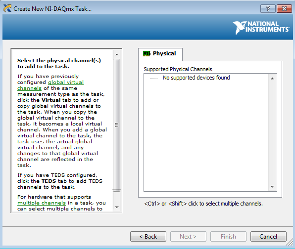
I am trying to create a development machine, where we can test the new code without using our physical hardware. I followed this guide to set up a system of simulation. I get to step 3.2 b, but the device does not appear in the DAQ assistant. MAX, the device self test and gites calibrated successfully, and when I open the test panels, I see some sort of signal. I guess that's a default entry simulated since I didn't that device to look for anything? Note that two devices, I am creating the show upward into the devices section and Interfaces, but that, even after running auto calibrate, automatic Calibration date is not yet specified.
When I try to test the device and create a voltage according to the guide, I can't see a device in the creator of data acquisition task.
Steps 1 and 2 of this guide are of course met. Step 3 is not, but this is not surprising because a simulated device is in device in any case manager. Also, I'm not under RT, so step 4 is satisfied.
Someone at - it ideas?
That would be because the PXI-5124 is a digitizer not an analog input device. You must use the NI SCOPE not NOR DAQmx driver
-
slowdown of acquisition (includes simulation)
I use a NOR-5124 to acquisition of data in burst mode. I noticed that it slows down considerably over time. I deleted the main parts of the code, its replacement by the simulated for acquiring data and the slowdown is still involved. I am running Windows XP, and bringing to the top the Task Manager to view the performance, you can see the treatment tips get more from the application runs. I don't see any obvious increase in memory, so I don't think that leaks memory are the issue. Someone has an idea of what's going on?
The application collects in fact 500 sets of 2000 samples, adding 500 sets together for a set of data accumulated from 2000 samples. Must repeat 2000 times so the final accumulation is 2000 x 500 combined collections resulting in a single Bay of 2000 sample. It is displayed on the other tabs, the user can watch individual collections for the bursting of the last 500 x 2000 collected.
ddemara,
I traced through your code a bit and noticed that you seem to be accumulating an increasing number of States 'pending' in your queue. I put a flag on the 'wait state get' vi 'Elements' out and seen the content of this table the application progressed. The application runs, the number of inactive States in the queue increases and increases the time between the loops. If you look at the output of elements on the State of the queue vi you will see what I mean.
I don't see anything in the code that suggested you a memory leak, I think it's the pileup of the idle state which is responsible for the delay.
see you soon,
-cb
-
Problem with the blue screen on Windows 7
Hello world
I'm looking inform my computer crashes a lot when editing in Adobe Premiere Pro. Computer guard market back but a small window with the following message: windows has recovered from an unexpected shutdown
Signature of the problem:
Problem event name: BlueScreen
OS version: 6.1.7601.2.1.0.768.3
Locale ID: 2057More information about the problem:
BCCode: 116
BCP1: FFFFFA801668F010
BCP2: FFFFF8800F9A11F0
BCP3: FFFFFFFFC000009A
BCP4: 0000000000000004
OS version: 6_1_7601
Service Pack: 1_0
Product: 768_1The system finds no solution for this problem, so I wonder if anyone has experienced similar problems and perhaps he could let me know how to deal, please.
Kind regards
Marcin.
Error checking 116, {fffffa80170aa4e0, fffff8800f9b41f0, ffffffffc000009a, 4}
Cannot load the image \SystemRoot\system32\DRIVERS\nvlddmkm.sys, 0n2 error Win32
WARNING: Unable to verify timestamp for nvlddmkm.sys<== nvidiav="">
ERROR: Module load completed but symbols can be loaded for nvlddmkm.sys
Probably caused by: nvlddmkm.sys (nvlddmkm + 8f91f0)Two things your BIOS needs to be updated. You're still at F4, which is the first version.
11: kd >! machineid sysinfo
Identification information of the machine [of Smbios 2.8, DMIVersion 39, size = 4177]
BiosMajorRelease = 5
BiosMinorRelease = 6
BiosVendor = American Megatrends Inc.
BiosVersion = F4
BiosReleaseDate = 18/08/2014
SystemManufacturer is Gigabyte Technology Co., Ltd..
SystemProductName = to be filled by O.E.M.
Family = to be filled by O.E.M.
SystemVersion = to be filled by O.E.M.
SystemSKU = to be filled by O.E.M.
BaseBoardManufacturer is Gigabyte Technology Co., Ltd..
BaseBoardProduct = X 99 - UD5 WIFI-CF
BaseBoardVersion = x.xBIOS OF WIFI-CF X 99 - UD5
http://www.gigabyte.com/products/product-page.aspx?pid=5124#BIOS
Please see the Wiki below, the link for details and troubleshooting tips.
BCC116 & BCC117 "has stopped your video driver.
Maybe you are looking for
-
I get the message; The general account settings. Windows Live team. Needed immediate attention. Noticed unusual activity in the account. Fill in the information will result in lock out within 48 hours. He asked my, name, username, password, date o
-
How can I uninstall a program that does not show in my add and remove program?
I downloaded a program called Imesh is a file sharing program. Should have never downloaded it. I can not even find an uninstall icon to remove it. I looked in the folder program files and it didn't no Imesh folder. When I click on the Start button
-
I am trying to configure my outlook express6 e-mail account
The problem I encounter is the message coming wrong incoming and outgoing server. What should I do? Please can I get instructions on how to set up? I configured the account under my sons computer but he has Windows 7 and his assistant set up the acco
-
"This operation has been cancelled due to restrictions in effect on this computer. Contact your system administrator. » I'M SORRY I DON'T KNOW WHAT MEAN THIS MESSAGE, I DON'T KNOW HOW I CAN CANCEL IT. THANK YOU FOR YOUR HELP
-
Multiple firewall RV042 external IP addresses
Hi, I hope someone can give me an example of what I need to do, if possible with the RV042 Main uses of IP address external port forward for some ports, all OK. I would like to have other external IPs assigned to computers on my local network Basic h