IMAQ classify concept VI necessary
Hello
How Labview classify objects using IMAQ rank VI?
What are the different parameters that it checks to determine if an object belongs to the class or not?
Any example to illustrate this will be very useful.
Concerning
Aveo
Hello aveo,.
I had the time to do some testing of classification, and maybe this can help you in your project somehow.
I follow the algorithm of paper to create a characteristic vector:
or
http://HAL.archives-ouvertes.fr/docs/00/75/25/09/PDF/118.PDF
I enclose this vi.
Then I created customized by using two examples of vectors classifier built characteristic, formed the nearest neighbor classifier and classified the sample (see the attached vi also).
Best regards
K
Tags: NI Hardware
Similar Questions
-
Identify several Classes in particles classifier
Hey guys!
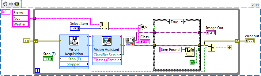
So, I do this VI that differentiates a nut and a washer and a screw. I use the classification of particles for the same. The problem lies here. I want the program to respond only to a particular type of object, even when there are several objects in the image. The IMAQ classify VI alone gives me a unique class of an image where objects of all 3 classes!
Can someone help me find a way around this problem? I enclose an excerpt from my VI below, as well as the VI.
Yes, sorry, I found the solution. A lot of my embarrassment, it was there before me. All I had to do was the result of matches of the wizard of vision and the search for the string in the table.
-
HI -.
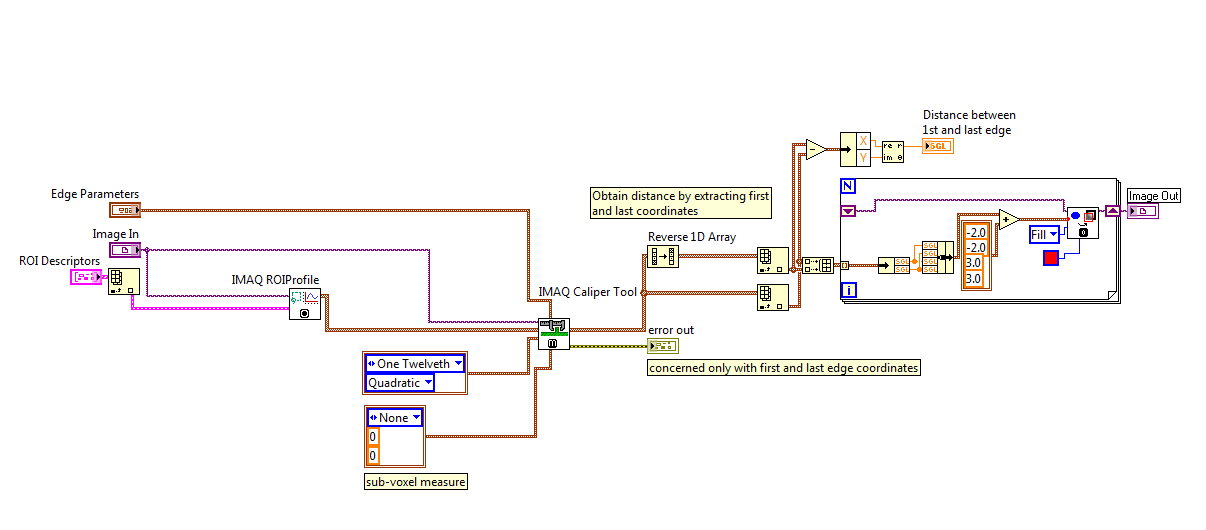
I want to superimpose the edge points found by using the IMAQ Guage VI line, very similar to how it's done in the "Example.vi of edge detection.
However, outputs only to the IMAQ line Guage VI are the distances. I can use the IMAQ Edge Tool 3 to get information of edge overlay, but it is not clear to me that the edge information provided by the IMAQ Edge Tool 3 is compatible with the calculations of the IMAQ line Guage VI. I need the subpixel accuracy.
Can someone let me know how we can do this with IMAQ line gasoline?
As another note, I tried to use tools IMAQ himself but was to have some very strange results for distances, that's why I turned to IMAQ line of gasoline, giving me good results.
Thank you
Don
The fixed. Missing IMAQ ROIProfile that is necessary to get the entry of correct coordinates for the caliper tool. But I think it would be easier to have just the edge information outgoing IMAQ line Guage VI since you can see that I had to manually write the code to get the first and last edge and remotely. This information is certainly somewhere in the line of gasoline VI. NOR would just add edge as output information.
-
Hi all
I want to get the list of Classes of the classifier color file. I used IMAQ classifier read of color, but it does not give the list of Classes.
I'm using Labview 2011.
Help, please.
Thanx
Classifier IMAQ precision refers, among other things, the list of classes.
Note that the classifier must be trained to use this VI.
Christophe
-
VI to calculate partial derivatives and curvature on a surface
I have a surface (a series of x, y, z triple that form a grid, measures, not a formula). I want to calculate the curvature at each point of the grid. I already have a smoothing and interpolation, so it doesn't have really sharp edges. I understand that I can not calculate curvature to the edge because I need adjacent squares. Is there a routine LV integrated for this or should I write my own?
If I have to write my own routine, I'll write a nested loop that goes along each row and column of the grid. At each point, I'll estimate the matrix of 2nd partial derivatives by finite differences. Since I have will calculate the maximum curavature, or a minimum radius of curvature, at this time there (once I found the formula, which I have not quite finished).
I appreciate all the suggestions; I hope that there is already a VI to do. Thank you.
Hi, WCR.
For the calculation of the curvature, we only have a VI IMAQ called "IMAQ classify Curvature.vi" (http://zone.ni.com/reference/en-XX/help/370281P-01/imaqvision/imaq_classify_curvature/) that will calculate the curvature for you. However, it is a function of the NOR-IMAQ driver, and it only accepts an image of contour. So if you don't plan to treat it with a photo, then you will have to calculate the minimum/maximum curvature with our artihmetic vi.
There is a VI that will compute the partial derivatives called "Derived partial of f (x 1, x 2) VI" (http://zone.ni.com/reference/en-XX/help/371361H-01/gmath/partial_derivatives_fx1x2/). It notably VI will calculate a 2D of two independent variables table.
I hope this helps!
-
Interpretation of data from stereo camera Bumblebee (PointGrey)?
Hi, first noted that I read the discussion at http://forums.ni.com/ni/board/message?board.id=200&message.id=11236
I am able to access the above stereo camera through my RESUME very well (using IMAQdx) and set it up through MAX. I am also able to access any of the cameras individually by using the option of Pan at MAX (I think I could set this on-the-fly by program, but I'll leave that for another time, less important now.
This is based on the information of PointGrey Research Inc. at http://www.ptgrey.com/support/kb/index.asp?a=4&q=312&ST=bumblebee
The same page also shows that if I place the stereo camera Bumblebee to use Format_7 Mode 3, the resulting 16 - bit image contains 8 bits of the camera on the left and 8 bits of the right camera. I checked (I think) that this is the case, since when I run a drain to the MAX with this mode, I am able to 'white-out' the display of the right camera covering the LEFT camera. And no, this camera no balancing light or such, as a confirmed it by covering the right camera.
So, my question is how can I retrieve this information? A simple matter of data manipulation, I think, but I'm stumped. For now I understand I probably can't do it using the screw IMAQ, would it be necessary to have a loop for, go through the binary bits and separate them? The info about what additional image, how do I know what it takes NOT to separate?
So conclusion, I have a thread of data type Image that contains a 16-bit image, and I would only split into 2 images to 8-bit based on the above.
Based on the advice of the manufacturer of the camera, I have extracted the appropriate data successfully, but now have a new problem, which I will present as a new thread.
For the record, I've used the IMAQdx get Image data VI to extract the raw (16 bit uint) image data and the split table with Decimate 1 d Array to two tables, their resize to the size of array appropriate 2D (640 x 480 for my case).
-
Hi all
What does IMAQ start? On my eval of camera position, it fails in certain circumstances, and I am trying to isolate the cause.
Reminder: There is a rating system provided to me by MAY. When I use it as they delivered, it works fine. But of course, I need to perform very differently than the design of the MAY, and that's where the trouble starts.
The system is a Lenovo ThinkCentre running Windows 7 Pro SP 1 64-bit.
NOR-1433 PCIe framegrabber, two Camera Link cables running to the eval Board.
LabVIEW 2010 32-bit version,
NOR-MAX version 5.5.0f0,
NOR-IMAQ version 4.7.3,
Camera files 3.0.1 generator
The eval system was originally designed as a step 4, CL Medium. To illustrate a concept we develop, I want to run 8-tap CL full (really, I want 10 bits 8 tap but that's another debate). I used CFG to change the original file of the ICD and saved as a new file. When I use NEITHER-Max to move to this new camera file, the program fails when IMAQ Start is called, error -1074397153 is returned. «NOR-IMAQ: impossible to detect a recognizable video source'.»» I'll join the two files from the CIM.
I see two possible culprits:
(1) IMAQ start is reading of registers on the camera and find something inconsistent with the settings in the file of CIM
(2) items in the bad file CIM contradict
Since it is a Sunday, I don't expect to get an answer very quickly, so I'll keep looking for my own solution for awhile. If I solve myself (excessively positive attitude), I'll post the solution.
Thank you!
Crazy
Exactly, cheese. And what was the real problem?
Ding ding ding ding ding!
No clock Z (or data, by the way). It seems that someone (blush) I forgot to UN-comment the lines in the file of constraint FPGA affecting the pins on Canal Z.
The moral of the story: don't even bother of the Forum until what you watch on the "scope of application.
See you soon!
Crazy
Another moral: framegrabbers are looking for a clock until they try to acquire.
-
Hello
I am trying to trace an image using a table 2D-data using IMAQ points.
Creating a grayscale image is fairly simple, but is it possible to display the image as a spectral color image? i.e. Red corresponds to higher values, of the lowest and green blue values between the two, with a range of colors visible.
All color for IMAQ functions seem to want an RGB input or some other encoding, but all I have is data digital bullies. Maybe I need to convert it somehow...
Thank you
Steve
Right-click your image viewer and select "Palette > Rainbow." It's exactly what you're looking for.
If the result is not compliance, you can create a custom palette and say the display of images to use by plugging your palette to the node of property "to Palette. Details can be taken from the Manual of Concepts of Vision. Details on pallets (also the rainbow palette) are here.
-
I have an application that consists of an executable file that dynamically loads the plug screws in sub-panels during operation. The plug screws vary from a system. A some less frequently used on the plug screws requires a driver IMAQ 4.1.
I might add IMAQ 4.1 installer for the executable, but since it is not necessary for most systems, that seems unnecessary. I could also use the installer of Acquisition of Vision, but I don't want my customers to have to deal with activation when they will use only a small piece of it anyway. Is there a Setup program or who would install ONLY the driver IMAQ 4.1 (and all the other required components)? Or someone can think of a better way to handle this?
Thanks in advance,
Jason
Hey Jason,
You use application builder to create an installer for your application? If you are, you should be able to include fair NOR-IMAQ, tab other installers just as you would include DAQmx and LabVIEW Run-time engine. That would be your best best. Otherwise, if you create your own setup program, you can check the read - me for NOR-IMAQ know what files are included with the driver and where they should be installed on the machines in deployment.
Hope this helps
-Ben
-
Question setting baud rate to IMAQ using Camera Link
I have a card PCIe-1433 to link camera, with a camera of Basler. I found that I can put the gain and exposure both directly in the camera with the help of the link series and order series. It works very well. I do this programmatically by using the CLAllSerial.DLL.
Series orders take too long to send in my application because of the default 9600 baud rate, so I was able to send a command to the Basler camera up to its transmission speed, then changing the baud rate of the port com series camera link for the match. The result is that I can quickly talk to the camera. Sweet so far.
However, with the Basler camera and camera link com serial port to the higher transmission speed, I can no longer acquire images using imgXXX IMAQ commands. I get a time-out of orders series IMAQ must use to control the camera for Imaging. Essentially the IMAQ driver does not know the baud rate change. I don't see how I can tell the IMAQ driver what output baud rate to use. Also, NEITHER MAX becomes unusable in this situation.
How can I, via the IMAQ driver, increase the speed of transmission of orders series to the camera via the connection of the camera?
See you soon,.
Wayne
So, I thought this close and post the solution. To increase the speed of transmission of communications series through camera link, you must:
-Use the NI Camera File Generator to change the file of the camera (or simply edit it directly, since it is the text file).
-Run NI MAX and connect to the camera using the new camera file. MAX will not be able to talk to the camera at the moment, because the speed of camera has not yet been changed.
-In your application, first set the link rate 9600 series, so you can talk to the camera. Now change the baud rate in the camera itself, using all save changes, etc., are necessary for the camera, you are connected to. Finally, change the speed of link series to baud rate selected in the file of the camera. (It goes without saying that the serial link baud rate and baud rate camera must match).
Now, both the driver AND AND the camera are according to the new baud rate. You can exit the application and allows to access your camera... until you turn off the camera... how he NI MAX (at least the Basler I use) restores baud rate 9600. Works great!
See you soon,.
Wayne
-
Hello... First of all a question about IMAQ... I've seen many examples of LabVIEW which includes IMAQ VI... What is necessary to own or buy to access these IMAQ vi? Second, what is IMAQ versus NI Vision? NEITHER Vision a more recent name for what was IMAQ or is it something else entirely?
I have a Developer Suite license and thanks to that I have many versions of LabVIEW Professional Developer Suite (PDS) LabVIEW through LabVIEW 2011 7 (does not have 2012). But I don't have any specific modules vision/image... All I really want to do is open a specific. TIF image and view this image on a LabVIEW front panel led. Short of owning any IMAQ or NI Vision vi, made the main PDS provides the tools I need to do this simple task?
And again, I'm lost in the word soup. What is IMAQ as compared or contrasted with NI Vision?
Thanks bob...
Hello Bob,
There is a lot of information to analyze through this question, let thus starts at the top.
NEITHER Vision is the platform of any vision that NEITHER has to offer. This can be broken down into two basic categories; Hardware and software. Hardware includes our smart cameras, Vision systems shipped, Frame Grabber cards (PCI, PXI, PCIe, SMU) and other material. The software can be decomposed into Vision Development Module (VDM) and the Vision Builder for Automated Inspection (VBAI). Sorry to throw in acronyms, but it will save some typing over the long term.
Vision Development Module, is the great global toolkit for LabVIEW Vision applications. The Vision Development Module includes several pieces of small software. These software include Machine Vision algorithms and several other pallets of treatment as well as the software of Acquisition Vision (SAV), which can be broken down into three additional parts. Here's where we come to the VI IMAQ, Vision Acquisition Software includes IMAQ IMAQ i/o and IMAQdx. IMAQ and IMAQ i/o are free software, and IMAQdx isn't.
Here's a quick preview
OR Vision
- Hardware solutions
- Smart cameras
- Embedded Vision systems
- PC and PXI systems
- Software
- Vision Builder for Automated Inspection
- Vision Development module
- Machine Vision algorithms
- VI image treatment
- Vision acquisition software
- IMAQ (free)
- IMAQ i/o (free)
- IMAQdx (paid)
Now, as for your specific application the Vision Development Module is not included in the Suite of developers at least that specifically added to your package. However, you will be able to acquire and save an image with the base IMAQ VI.
IMAQ means Acquisition of Image and is a driver package for communications standards of different camera as well as several basic image manipulations. With the free IMAQ driver, you will have access to the VI listed in the knowledge base following.
The screws are installed with NOR-IMAQ and Acquisition of Vision Software?
http://digital.NI.com/public.nsf/allkb/1c4ed6177ee566d68625794a007ba160?OpenDocument
You can download the latest version of IMAQ here:
http://Joule.NI.com/nidu/CDs/view/p/ID/2758/lang/en
Alternatively, you can download a trial version of the software for Acquisition of Vision and then allow the functions of IMAQdx paid become invalid at the end of the trial period.
http://sine.NI.com/NIPs/CDs/view/p/lang/en/NID/12892
Once you have the IMAQ VI installed you should be able to open the. TIF file and display it using the ReadFile.VI IMAQ and an indicator of the image.
I hope that clarifies the differences of our Vision, and how you can access to the. TIF file.
See you soon,.
Joel
-
IMAQ Grab Acquire.vi error when you use an external trigger on a card NI PCIe-1433 (sync problem?)
According to my recent post on getting up and running with the NI PCIe-1433 camera link card, I ran into a bit of a snag.
When you use the internal trigger on the camera, everything works 100%. I can view all the data from the camera in MAX as well as in the labview project. However, whenever I have set the mode switch is where things start to fall apart.
What I have confirmed:
-Camera is switching between inside and outside triggering.
-NI PCIe-1433 camera link card is set up properly. While in external mode, I can trigger the camera by using a function generator and check the wire to the MAX. Everything works fine.
When the unit is in external mode, the function Acquire.vi enter IMAQ - my mistake VI. The error is:
Code :-1074397150
The possible reasons for a timeout.
Now, I have it set up so that a mistake here will not end the LabVIEW file. Sometimes, data of interest makes however (about every 10 seconds-ish). So what seems to be the case, it's that this external trigger signal is not in the lineup when the clamp is attempted. Is it possible to synchronize these? May reference the trigger signal external sort in my LabVIEW project so that the clamp is performed only when that trigger impulses?
So I solved my problem. He was in time. The external trigger that I used for the device was simply too slow. I was initially using a trigger from 2 Hz to be able to view the values changing on LabVIEW probes. But it was enough to get enough data to move above the camera cable to assemble a picture and kept it in time. Travel up to 9 kHz solved the problem. No adjustment to the camera settings or LabVIEW code was necessary.
-
Hello!
I am video capture with IMAQ.
I have a hand program and a Subvi, which made the acquisition.
When I use the Create.vi IMAQ to allocate say 5000 photos in the Subvi runns all fine
but whenever I call the Subvi there is a delay until all images are ready for the acquisition.
So I tried to make the distribution of the hand-Programm-VI where is enough time to do this while the user makes other things.
Then I put a reference or a single entry to the Subvi with table empty I allocated.
When I run the program now acquiring works but is about 10 x slower than before.
What's wrong? Why ventilation is in the Subvi to run at normal speed?
Welcome C.Riedel
Thanks to all who tried to help, but I found a solution (unsatisfactory).
I completely Redid the Subvi by copying and pasting the code in parts to a new VI...
and it works now. Jey!
So Bruce was good, the concept is correct. Thanks for that!
The source of probs remains unknown... NaH... but fortunately it works now!
-
IMAQ AVI2 write leak memory frame
There is a bug report. Writing great images 2160 x 1080 AVI file without compression CODECs causes the memory usage go back upwards, until LabVIEW fundamentally exceeds the limit of 8 GB memory and stops processing the images.
Hi John,.
I reproduced it and classified CAR 428325 for her. At first glance it seems to be only a problem when the color of the AVI format does not match the format of the input images you write. In your case you pass U8 images in but the written video AVI, YUV (color) images. If you pass the VI to create IMAQ to create images of RGB32 instead, the leak disappears. Switching to Y800 AVI format (uncompressed monochrome) instead of changing the side of the entrance shows no leaks either.
If you do not actually want the disparity of monochrome image processing and color AVI format, you can work around this problem by putting a VI Cast into your code to convert the U8 RGB32 image before writing in the AVI file.
Eric
-
several webcams in for usb or imaq vision Builder
Hello
I have a question about imaq nor for usb or vision builder AI 3.6 (I did a vi with imaq and I run in the constructor of the vision) and I want to know how can I connect multiple webcams to the computer, and how many of them can be connected. can they all be of a make and model and can they be executed with a driver installed on the computer?
Thank you
Hello
In general NOR-IMAQ for USB can support only one camera at a time. You can acquire multiple cameras (not simultaneously) using USB IMAQ list VI cameras to identify each device plugged into your system and access it via the other IMAQ live to USB.
I would also like to point out that Vision Builder AI does not support the NO-IMAQ for cameras USB driver. It is designed to solve machine vision applications, but USB cameras provide in general or advanced necessary for machine vision triggering modes. Because the machine vision and USB cameras will usually together, we do support USB cameras in Vision Builder AI.
Maybe you are looking for
-
I have an Iphone OS. How to upgrade Itunes on my phone.
I have an Iphone OS. How to upgrade Itunes on my phone.
-
I installed won 7 out of old computer, keeps crashing. just not enough anything to run right. question is this. can I remove between this computer and install it on the newer than Dad has given me everything. It has vista and adviser said that it wil
-
Failed installation of CUCM IM and presence in be6k
Dear all, There is a new facility in our lab on be6k, we have completed the installation of CUCM. However, we cannot install the CUCM IM and presence in the be6k in the section "first node access configuration. Please refer to the photo 1/2/3. I crea
-
External access to a single server Via VPN
Hello I borrowed from a router (878) customers using the VPN Client, they can access what they need in their own country. A new requirment has developed, there is a hosted server that has IP restrictions so that only a range of internal addresses can
-
even after the resolution of the problems windows update error 80072E2 comes.i need the updat kb2871389 bfore updated to windows 8.1, please help