ImaqSession.Acquisition questions.
Try to use the new ImaqSession stuff and I have a few questions:
1. all samples seem to use a background worker. Why, instead of using the ImaqSession.Acquisition.AcquireCompleted event? Examples of the use of this?
2. How can I erase the image of an ImageViewer? Used to be able to detach.
3. What is the difference between ImaqSession.Acquisition.Extract and ImaqSession.Acquisition.Copy?
Thank you
Don
Hi Don,
I don't know exactly what you ask your first question, can you please better explain what you are looking for. Regarding the compensation of your image, you can use features. The difference between the extract and copy is with extract, you can select your size X and Y. Please see the documents below, they explain the functionally VI for LabVIEW, but the same should apply in your coding environment.
IMAQ extract VI
http://zone.NI.com/reference/en-XX/help/370281P-01/imaqvision/imaq_extract/
IMAQ copies VI
http://zone.NI.com/reference/en-XX/help/370281P-01/imaqvision/imaq_copy/
IMAQ has VI
http://zone.NI.com/reference/en-XX/help/370281P-01/imaqvision/imaq_dispose/
Tim O
Tags: NI Hardware
Similar Questions
-
Simple Data Acquisition question please Help!
I have problems with a simple LabVIEW program.
I'm analyzing two inputs voltage and at the moment I have the VI work so that both are analyzed at 10 k Hz simultaneously and displayed in two tables of waveform. What I would do, it is write values for them at 1 Hz in an excel spreadsheet or a text file with the time, the value of the first and the second value. So I would create an array of [value1, value2] and export that to a line in a text file, I can analyze and then later in excellent. I want to keep it that way for the duration of the program. In addition, it is possible to have the LabVIEW to generate such a table statistics once the user closes the loop, it would be even better.
I can only assume that it is not too complicated, but I've never done any export data and just a quick explanation probably will save me a lot of time. Any help would be great, even if it's just to say "use this feature. Thank you very much.
Pieter
Pieter,
Please post on the Forums of NOR. I could take an example that was similar to yours and organize data in the format you want. I've included a photo as well as saved for LabVIEW 8.6 VI. I took the data from the berries that were from the channel to read and handle while he was in the format of time, channel 0 channel 1. Hope this helps and let me know if you have any questions. Thank you!
-
Hello
I have a pair of SPI devices and a pair of NI USB8452 RENAULT and one machine I want to do my reading of. It seems that it shouldn't be a problem, but the second device is throwing an error when I call ni845xSpiStreamRead (specifically, error 0xFFFB6569, making StatusToString as "an unknown error has occurred"). The problem occurs only when I try to do a SPI stream to read on the second device - either by itself works very well.The flow of the program is:
- Discover all devices using ni845xFindDevices and then calls ni845xFindDeviceNext.
- Open each device using ni845xOpen.
- For each device, create a device Configuration using ni845xSpiConfigurationOpen. Set up to contain all values that are appropriate (clock phase, polarity).
- For each device associated with his apparatus Configuration, perform some operations of ni845xSpiWriteRead to verify that they work. The successor to this part.
- For each device, create a device of StreamConfiguratin using ni845xSpiStreamConfigurationOpen. Implement those to contain the appropriate values and timing information.
- For each device, run ni845xSpiStreamStart, with its appropriate StreamConfiguration.
- Enter a while loop, and for each iteration of the loop, run ni845xSpiStreamRead, given a device, its StreamConfiguration and its own segment previously-malloced memory to write to.
Step 7 is where the error is displayed.
This would not more simple (but also annoying), if two devices cannot simultaneously. Casual, however, I do not know why this would be the case; I understand the role of the computer in streaming mode to move a block of statements to data acquisition and data acquisition does all the heavy lifting, while computer demand sometimes just data. In such a case, the number of devices does not appear that it would be important to the computer. Is it not the case? I looked through the documentation and not not seen an answer one way or another. (the documentation is clear that streaming mode allows a data acquisition question one device, but this isn't what I'm asking)
Therefore, the following two questions:
- A computer can read data from two Renault which are both in streaming mode at the same time?
- Why, in my particular case, maybe the two Renault not cooperated in streaming mode specifically?
Embarassingly, I am answering my own question once again.
(1) two Renault can work simultaneously in streaming mode. This may also be true for the case of n - DAQ, but I don't know who.
(2) 0xFFFB6569 seems to throw when you pass a pointer not valid uInt8 to ni845xSpiStreamRead.
In short, I've been mallocing the size of the readFromDevice table based on the value of "DEVICES" and make ni845xSpiStreamRead (int i = 0; i)
It is ridiculous to make an error, but I'm leaving this here in case someone else makes the same mistake and lifted eyes this specific error code.
-
Question about the Acquisition continues through NOR-DAQmx
I'm a bit new to NIDAQmx methodology and I was wondering if someone could could give me some advice on accelerating certain measures of tension that I do with a case of DAQ NI USB-6363.
I have a python script that controls and takes measurements with a few pieces of equipment of laboratory by GPIB and also takes measurements in the area of DAQ OR DAQmx via (I use a library wrapper called pylibdaqmx that interfaces with the libraries C native). As I do with the data acquisition unit is 32 k samples at 2 MHz with a differential pair to AI0. An example of code that performs this operation is:
from nidaqmx import AnalogInputTask

# set up task & input channeltask = AnalogInputTask()
task.create_voltage_channel(phys_channel='Dev1/ai0', terminal='diff',       min_val=0., max_val=5.)
task.configure_timing_sample_clock(rate=2e6, sample_mode='finite',
      samples_per_channel=32000)

for i in range(number_of_loops):  < ... set up/adjust instruments ... >  task.start()  # returns an array of 32k float64 samples  # (same as DAQmxReadAnalogF64 in the C API)  data = task.read(32000)  task.stop()  < ... process data ... >

# clear task, release resourcestask.clear()del task< ... etc ... >
The code works fine and I can all the 32 k spot samples, but if I want to repeat this step several times in a loop, I start and stop the job every time, which takes some time and is really slow down my overall measure.
I thought that maybe there is a way to speed up by configuring the task for continuous sample mode and just read from the channel when I want the data, but when I configure the sample for the continuous mode clock and you issue the command of reading, NOR-DAQmx gives me an error saying that the samples are no longer available , and I need to slow the rate of acquisition or increase the size of the buffer. (I'm guessing the API wants to shoot the first 32 k samples in the buffer zone, but they have already been replaced at the time wherever I can playback control).
What I wonder is: How can I configure the task to make the box DAQ acquire samples continuously, but give me only the last 32 samples buffer on demand k? Looks like I'm missing something basic here, maybe some kind of trigger that I need to put in place before reading? It doesn't seem like it should be hard to do, but as I said, I'm kinda a newbie to this.
I understand the implementation of python that I use is not something that is supported by NEITHER, but if someone could give me some examples of how to perform a measure like this in LabView or C (or any other ideas you have to accelerate such action), I can test in these environments and to implement on my own with python.
Thanks in advance!
Toki
This is something I do a bit, but I can only describe how I would do it in LabVIEW - I'm no help on the details of the C function prototypes or the python wrapper.
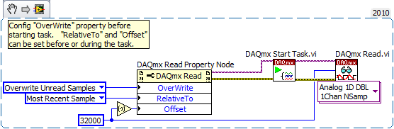
In LabVIEW, there are accessed via the 'DAQmx Read property node' properties that help to implement. One is the Mode "crush" which I'm sure must be set before performing the operation. The other pair is known as "RelativeTo" and "Offset" and they allow you to specify what part of the CQI data buffer to read data from. If you the config to "RelativeTo" = 'most recent sample' and 'Offset' =-32000, then whenever you read 32000 samples, they are the very latest 32000 which are already available in the buffer of data acq. Between the readings, the task is free to overwrite the old data indefinitely.
Note that you will need to do this continuous sampling mode and that you can explicitly set a buffer size smaller than the default which will choose DAQmx based on your fast sampling rate.
An excerpt from LV 2010:
-Kevin P
-
Hey guys, hope someone can help me with this, or atleast send me in the right direction...
I have an output of two channels of my oscilliscope on my screen, works very well.
However, I is not necessary to watch these waveforms - what I actually do is monitor 4 points on them over time and see how they change during my test. Two channels, so I need to generate 8 separate graphics where x represents the time and there is the voltage level of these points.
I have attached a screenshot that I have edited in paint, to show exactly what points I care - signified by red circles. Please take a look and get some ideas on how to do it. If you need me to be more specific, I'd be more than happy to.
Thanks for reading this, peace.
OK, I'm going to assume that the scale is really in time (MS).
You want to take the points at T = 19 mSec, T = 56 ms, T = 84 mSec and T = 122 mSec (judging by your points on the graph).
I'll assume that you have 50 mSec data before firing.
Thus, your points are T = 69 mSec, T = 106 mSec, T = 134 mSec and T = 172 mSec OF EARLY registration.
I guess you were sampling to 1000 Hz. (just the eye).
-
data acquisition multiple tank fitting: noob question
Guy
I want to connect 4 tank mimic DAQ Assistant with 4 current inputs.
But see vi did I connect the tanks correctly to the DAQ assistant? I don't know where to find the settings to affect tell tank1 current input1 and so on. I don't have the DAQ hardware to test my vi yet.
Thank you!
Split signals on the Express/Signal handling pallet.
-
Question about the Installation of Windows XP on Portege 3500 home
I have a second hand Portege 3500 with WXP tablet 2005 Server Pack 2 market version, but without the original disks. However, recently had a virus that did something to Prime the area on the hard disk. I have removed the virus but now get unexpected core dumps memory and system restarts when you try to connect to the internet.
Question: can I go down a level and safely install ordinary WXP software to work around the problem or the acquisition of new version of WXP Tablet and reinstall the software to circumvent the problem of core dump?
Installation of an operating system on this laptop, it's the hardest thing I have ever tried to do. Once start you, you will notice that there is no device boot attached to this pc. To install windows, yourself, the only options are to buy the cdrom drive for this laptop toshiba external or install via a network.
The toshiba cdrom drive is now quite obsolete, more expensive and the external device only that the laptop starts from (I tried with the other external cdroms, DVDs, disks usb keys and hard). It seems extremely difficult to boot from lan unless you already manage it infrastructure of the company. It is possible in theory, but after 3 weeks I still hadn't thought about her.
My solution at the end of the day was to send it to my local toshiba support center and ask them to re - install for me (he happened to have one in stock toshiba cdrom burners). I got the installation cd, so I guess you will need get these images from toshiba as well (or buy another os).
Good luck!
-
IMAQdx Get Image2.vi questions...
I've been running a program of vission machine for some time. Recently, I did an executable and Installer to transfer it to another PC and will have questions.
The program crashes on trying to acquire its first image. It throws the error 1074360293 to "IMAQdx to Image2.vi. As far as I can see, nowhere in the program is this called function. The closest I can find is in the image grab VI, but uses 'IMAQdx Get Image.vi' without mounted 2. So I don't know why it's looking for it.
Does anyone know where else this VI could be called from? To try to solve this problem, I even installed the same Vision on the new PC programs to bring on the same files.
Thank you
You will not be able to run even the VI if LabVIEW does not find the file. But if you can run the VI, the file exists on your system somewhere.
The VI is actually inside a .llb, so a file search won't be able to find it. Here's where:
C:\Program Files (x 86) \National Instruments\LabVIEW 2015\vi.lib\vision\driver\IMAQdx.llb
The only way I can think to mix the original versions and '2' of the screw are if you have changed the VI on several systems, and each system has had different versions of Vision Acquisition installed. I can't think of another possibility that would entail.
-
Number of averages for time waveform acquisition
Hello
It is on the configuration of the device - settings of the acquisition.
in the parameters of the collection file, can I know is there a way to feed the number of averages and % of overlap between averages aquire waving time.
Thank you!!
BR
Pattabi
In version 3.0 of InsightCM, we will support an average and overlap on the data of the spectrum Viewer. These settings will be applied only to the visualization of the spectral data and will not apply to calculations on the waveform or spectral data form.
This will meet your needs? Or are you interested in doing an average and are superimposed on the spectral data to then be used for calculations that are based on spectral data - such as 1 x Magnitude, etc.. ?
Thanks for the question.
-alan
-
Hi all
I have an old test set-up which has an obsolete VME controller and I need to duplicate the tester and make a new one.
My question is, can I replace the VME controller with any other type of Board? like, for example, a data acquisition card and a PC?
Do I need to use again the VXI/VME? or I can go with a data acquisition card and a PC too?
Not sure if this is possible because of the level of signal VME (?), but I thought I have ask the experts and double checking.
Thank you very much
If the pci card specifications are identical or more and you're ready to rewrite the software, so I don't see why not.
-
How to filter the traces of tension TDMS after acquisition?
Simple question. We have acquired a lot of electrophysiological data with express signal. We now need to filter data after the acquisition for later analysis. I can import the files TDMS tension of previous experiences, but can't seem to run the filters we used on the side of the acquisition to filter the existing traces. Is there a simple way to do this?
-smb
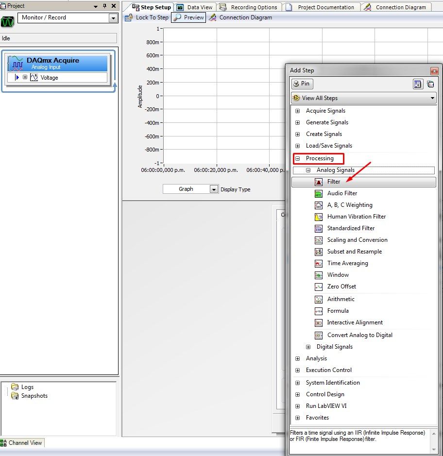
Hello Chinchilla,
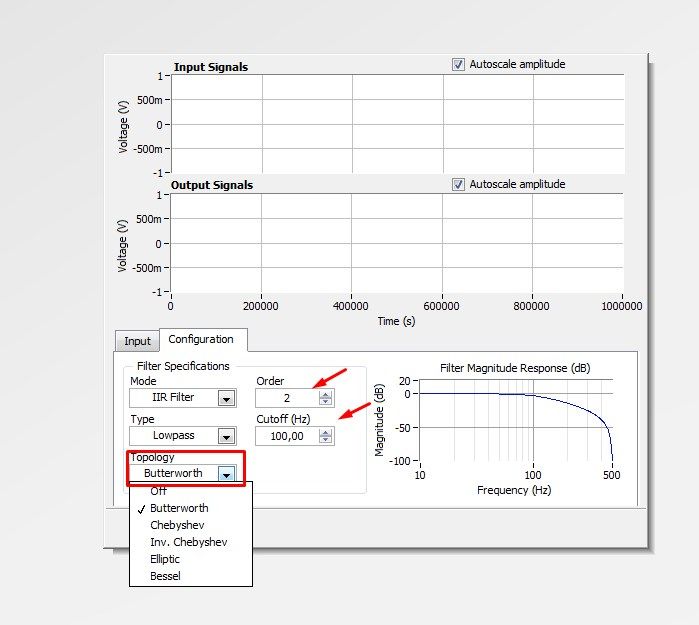
I enclose a few screenshots on how to add a step to an analog input filtering. You can select the type of filter and order too.
In this screenshot you can check how to change the configuration of the filter
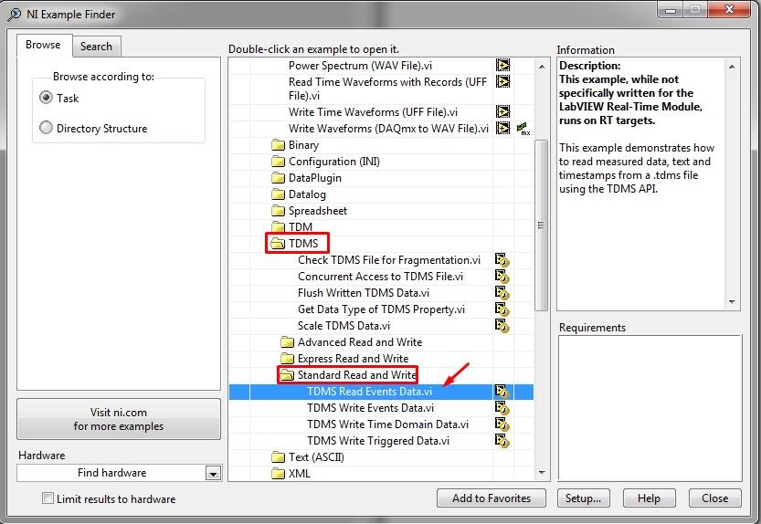
Finally, you can access the TDMS of LabVIEW file with one of the examples of PDM. Please follow these instructions:
1. open LabVIEW
2 - go to help > find examples to open the Finder 'example '.
3 - Go to Fundamentals > file Input and Output > TDMS > Standard Read and Write and select the VI named TDMS read Events.vi
You will need to know the data present in the file to read correctly. For this, you can use the leading PDM Viewer VI:
http://zone.NI.com/reference/en-XX/help/371361K-01/Glang/tdms_file_viewer/
Or you can use the Toolbox for excel: http://www.ni.com/example/27944/en/ (allows you to transfer the data to Microsoft Excel).
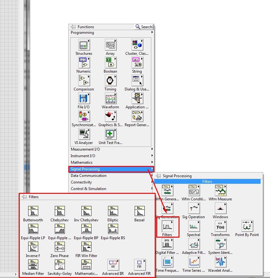
4. After reviewing the data, you will need to apply a filter. You can find the filter functions in the range of Signal Processing.
Please let me know if you have any questions on this subject.
Kind regards
-
Here's my question:
I have two different cards installed in a PC. Specifically, PCI-6224 and PCI-6254. I need to acquire 50 analog inputs (real time). Can I use two cards to do? I mean I can synchronize these two cards and acquire simultaneously several channels at the same time?
Thank you
Alessandro
Yes. You can use a RTSI cable between them. See the examples of the expedition. If you are using LabVIEW, look at several Synch - Analog Input - Cont Acquisition devices.
-
motion control for vertical actuator and data acquisition
Hello
I am a researcher (a branch of civil engineering) geotechnical engineering and I have very little knowledge about the acquisition of control and data motion, so would need a lot of help from the experts OR. I have only knowledge base on these 2 aspects based on my reading of some materials on the Web site of NOR and youtube videos, so I hope that you bare with me
 . Here are my questions:
I am trying to build an actuator which will be used to push a probe (a penetrometer with a load cell to measure the resistance of a soil sample), resembling the concept, photography in the attached file. I need to have these criteria for my system:
(1) actuator, which can push the probe at speeds between 0.01 mm/s - 300 mm/s with precision and move the probe cyclically (upwards and downwards) in the vertical direction
(2) load expected on the probe into the ground range: 0.02kN - 6 kN.
(3) necessary to get the load cell load data and the speed of the probe.4) able to control the actuator to a PC (speed and posotion) and monitor data from transducers and data log time even the transducers.
Guess my beginners is that I will need:
For orders:
(1) software - LabVIEW and NOR-motion assistant(2) controller - NI PCI-7342
(3) driver/amplifier - analogue servo AKD Drive
(4) motor - motor brushless servo AKM
For the acquisition:
(1) software - based LabVIEW development systems(2) amplifiers or other device - no idea what type on the conditioning of signals
(3) data acquisition device - no idea what type
Since I'm a beginner, is - that someone might recommend components (hardware and software) for the control and data acquisition. I'm on a tight budget, so I thankful if someone could help me to recommend components good enough to build my system.
Thanks for your help.
At these rates, you will need to run the sensor for the cDAQ. You can configure the analog output on the Tritex nationally on the position. There is an adjustable filter that you can set in order to get a clean enough to 300 Hz signal. When you learn about the Tritex, make sure that let you them know what comms and e/s that you want to use. If I remember, not all options have worked together. The analog output may need to be my, but you can put a resistance through the acquisition of input data to get the voltage instead. I don't remember all the details. You should really not too much on the Tritex/LabVIEW side. You will send your movement parameters (beginning of end of race, speed, position, accel, cut), and if you cycle (I believe you) or simply running in a loop. You could also just be able to use the functions of jog. When you get close to knowing exaclty what you need, PM me and I'm sure we can work something out with the drivers. You need only the basics. In fact, you could probably do this all your movements via digital and analog i/o.
-
Triggering off the coast of beginning of Pulse Audio in question DAQmx...
Hi guys,.
First of all, it is more a matter of software than hardware, so I didn't post this specific question in the multifunction DAQ card...
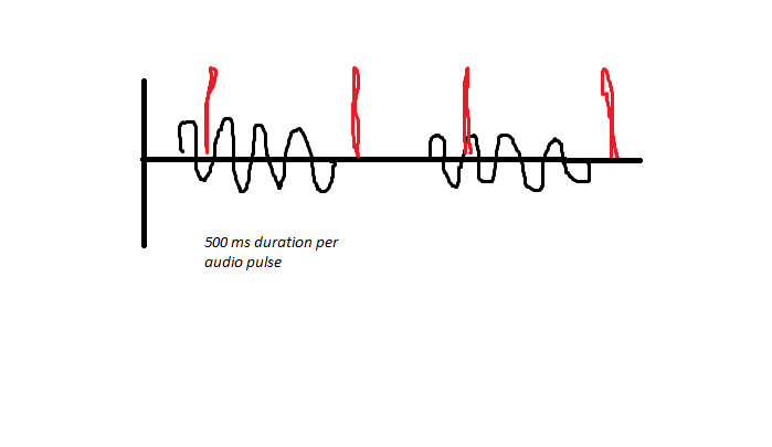
So I'll try to trigger an acquisition finished off the start of a pulse audio, however I have audio sync issues, due to the fact that it can be started before my VI runs. As noted below, the audio is generated and pulsed for 500ms on and 500 ms off the coast, and between these periods, a digital pulse is generated this way (shown in red). I have a problem to stay synchronized, due to the fact that I samples finished for 1 second of a data value, and if the USE EEG is faster than me, I can catch the pulse audio at Midway, rather than at the beginning.
I'm trigger analog outboard of a sound signal of 50mV and capturing two audio channels simultaneously and consistently captures 3 digital channels when they receive the trigger of the beginning of analog input trigger reference digital edge. If digital are slaves and audio is the master in this configuration. The point of this is to get a delta timed material at the time rather than use the timestamps of windows.
As I said, I use an Analog Edge Trigger Start to start my purchase, what triggers the digital task Digital Edge Start Trigger to start as well. How can I make sure that I start at the BEGINNING of a new pulse audio if I get out of sync, I can't understand this logic... Analog edge goes off just when it goes to the specified level, but maybe it's at half way through the 500ms pulse, so this is my problem...
I need to be a trigger to start because I do 55 000 this test iterations in a QMH Prod/consumer model and need relaxation to be redeclenchables and start-up is only redeclenchables.
The variability in timing you see at points 2 and 4 somewhat dictate against the possibility to set up a re-triggering precisely timed by the hardware configuration. I think that you need to abandon the idea of making repeated sampling finished back to back and switch volleys in a mode of continuous acquisition and treatment.
To help with this, I aim to capture the moments of digital via meter rather than DIO pulses and be ready to give up the acquisition rate noise much (if necessary) given that you said that your main concern is to distinguish between ON and OFF.
I must configure the counter to use the Digital pulse as a sample clock and use the sample clock signal HAVE the "time base", i.e. the signal which the edges will be counted and buffered in memory. This will give you 2 samples per second instead of 5 M and the values of the counter at these sampling points is the index in your AI data which occurred impulses. Pretty neat and clean. Just be sure to start the task of counter in front of the task to HAVE it.
-Kevin P
-
Digital relay of data acquisition
Hello
I quickly ask you questions. Can I connect several relay digital for single block scb - 68 (data acquisition is: 6321 PCI)?
With Labview, I want to enable or disable each of these relays. Is this technically possible? because never, I have connected several sensors to scb - 68.
Each relay acts as a binary switch to a motor brush continuous (3-12 v and RPM motor voltage: 11.5 krm with weight)< 80="" grams).="" the="" dc="" motors="" will="" receive="" power="" from="" external="" dc="" power="" supply="" unit.="" so="" the="" power="" for="" the="" relays="" (i="" am="" thinking)="" must="" be="" from="" daq.="" but="" i="" know="" daq="" can="" supply="" only="" very="" very="" less="" current.="" i="" am="" trying="" to="" source="" out="" if="" i="" can="" find="" relays="" that="" run="" with="" very="" current="" (which="" could="" be="" supplied="" by="" the="" daq="" itself)="" can="" you="" suggest="" me="" if="" this="" is="" possible?="" and="" also="" any="" information="" or="" source="" for="" the="" required="" digital="" relays="" would="" be="" lot="">
Thank you
MSC
Maybe you are looking for
-
Replace the RAM memory on TOSHIBA NB510
Hello I just bought a Toshiba NB 510 - 10 d and I just can't find where should I change the RAM memory. Can someone help me? Thank you!
-
Satellite A300-1BZ - 2nd location on hard disk?
Hi friends I'm new to this forum so forgive me if I don't post under the good discussion! First of all, I wanted to know if a 2nd HARD drive can be added to my Satellite A300-1BZ (PSAJ4E-03L016KS)? If this is not possible, no one knows what is the la
-
Serious problem with 1415-s105!
My mouse does not work nor does the Tablet, I get the:0 x 00031402, 0 x 00000002 touch ED error. Also my CD player does not work, so the restore disks are out of the question. I havereally need help. My warranty is also arrived in term. I have aflopp
-
Remove the admin account el capitan
I want to delete a temporary admin account I created to solve a security issue on my main admin account. In short, I want to delete one of the two accounts of user admin my operating system is the latest version of El Capitan.
-
ePrint, set up but do not list on google cloud
I have correctly configured my all in a single D110 for hp eprint. And set the option allow google cloud print, but it does not show on my list of printers. I added the printer on the registration page and he says that he is already registered and