Digital relay of data acquisition
Hello
I quickly ask you questions. Can I connect several relay digital for single block scb - 68 (data acquisition is: 6321 PCI)?
With Labview, I want to enable or disable each of these relays. Is this technically possible? because never, I have connected several sensors to scb - 68.
Each relay acts as a binary switch to a motor brush continuous (3-12 v and RPM motor voltage: 11.5 krm with weight)< 80="" grams).="" the="" dc="" motors="" will="" receive="" power="" from="" external="" dc="" power="" supply="" unit.="" so="" the="" power="" for="" the="" relays="" (i="" am="" thinking)="" must="" be="" from="" daq.="" but="" i="" know="" daq="" can="" supply="" only="" very="" very="" less="" current.="" i="" am="" trying="" to="" source="" out="" if="" i="" can="" find="" relays="" that="" run="" with="" very="" current="" (which="" could="" be="" supplied="" by="" the="" daq="" itself)="" can="" you="" suggest="" me="" if="" this="" is="" possible?="" and="" also="" any="" information="" or="" source="" for="" the="" required="" digital="" relays="" would="" be="" lot="">
Thank you
MSC
Tags: NI Hardware
Similar Questions
-
the relay control data acquisition
I am creating a vi that controls (press and release) several relay using a USB 6501 data acquisition. This should be a task relativily easy but I get flumoxed by errors. I tried to use the examples, but I get an error telling me that I need to use the mode of generation 1 sample (on request). Help, please
Sure. The easiest way is to have a DAQmx writing followed by a function of delay, followed by another entry, followed by another period. Simply plug the error links in order to control the flow of data. However, the VI would be insensitive so you can use a state machine or function elapsed time so that the VI can be stopped without waiting for waiting for him at the end.
-
digital triggering of stop/start of analog data acquisition
I want to use a signal from a digital line to start and stop analog data acquisition. The signal can change levels several times during a race of the VI so I have to start and stop several times data acquisition and store each session data in a different file.
I tried to play with the following screw: digital triggering of break, DigitalStartandStopTrigger and ContAcq_DigTrig. None of them doesn't seem to work for my configuration. I also do continuous data acquisition so I can't use a reference. I use PCI 6259 DAQ.
I used the "P0" pins rather than PFI pin on the grid BNC-2090. I know... stupid enough.
-
USB 6008 data acquisition: automatically turning in a port
Hi all someone could please help me.
I need to autoamtically send output didgital since my data acquisition based on a value. the bottom of my little project. I read in a database if a value is equal to a certain value, I want to send a digital camera of the signal of acquiring data in a relay, so for example if the value 1 database generates a digital signl 0 7 port line.
If someone could help it would be much appreciated
So what's the problem with sending AUTOMATICALLY one. You simply compare the value of the database. A comparison function returns a true or false, which is quite ideal to display a true/false signal.
Fix the code you wrote. This is not a service of howework and see some code real goes a long way to get detailed help.
-
Data acquisition reading incorrect when you use a loop
Hello
I wrote a simple VI (00, 01, 10, and 11) output to a circuit connected with 4 resistors. Based on what value the ciruit receives, it passes current through a particular resistance. It is again entered in Labview and traced.
The problem is when I send a particular value (i.e the 00, 01 and 10 and 11) and get that back, it's okay. But when I send and receive the consectively connected via the loop counter, they are incorrect (not synchronized with the number of the loop).
I made sure that circuit works very well. It has something to do with the loop synnchronization, reset, value compensation, etc. can be.
Please Guide...
Change your DAQ assistant that reads to be 1 sample on request.
Right now it is set for continuous samples. And 10 samples at 10 Hz. Then it runs and starts. The next iteration, you send a new digital out, but the wait for 4 seconds. When you read again, you get the next 10 samples that are put into the buffer of data acquisition, but now 40 samples have actually entered the DAQ buffer. In time your DAQ buffer will be finally complete and raise an error. In the meantime, you will continually read data continues to become more tainted by the iteration.
-
motion control for vertical actuator and data acquisition
Hello
I am a researcher (a branch of civil engineering) geotechnical engineering and I have very little knowledge about the acquisition of control and data motion, so would need a lot of help from the experts OR. I have only knowledge base on these 2 aspects based on my reading of some materials on the Web site of NOR and youtube videos, so I hope that you bare with me
 . Here are my questions:
I am trying to build an actuator which will be used to push a probe (a penetrometer with a load cell to measure the resistance of a soil sample), resembling the concept, photography in the attached file. I need to have these criteria for my system:
(1) actuator, which can push the probe at speeds between 0.01 mm/s - 300 mm/s with precision and move the probe cyclically (upwards and downwards) in the vertical direction
(2) load expected on the probe into the ground range: 0.02kN - 6 kN.
(3) necessary to get the load cell load data and the speed of the probe.4) able to control the actuator to a PC (speed and posotion) and monitor data from transducers and data log time even the transducers.
Guess my beginners is that I will need:
For orders:
(1) software - LabVIEW and NOR-motion assistant(2) controller - NI PCI-7342
(3) driver/amplifier - analogue servo AKD Drive
(4) motor - motor brushless servo AKM
For the acquisition:
(1) software - based LabVIEW development systems(2) amplifiers or other device - no idea what type on the conditioning of signals
(3) data acquisition device - no idea what type
Since I'm a beginner, is - that someone might recommend components (hardware and software) for the control and data acquisition. I'm on a tight budget, so I thankful if someone could help me to recommend components good enough to build my system.
Thanks for your help.
At these rates, you will need to run the sensor for the cDAQ. You can configure the analog output on the Tritex nationally on the position. There is an adjustable filter that you can set in order to get a clean enough to 300 Hz signal. When you learn about the Tritex, make sure that let you them know what comms and e/s that you want to use. If I remember, not all options have worked together. The analog output may need to be my, but you can put a resistance through the acquisition of input data to get the voltage instead. I don't remember all the details. You should really not too much on the Tritex/LabVIEW side. You will send your movement parameters (beginning of end of race, speed, position, accel, cut), and if you cycle (I believe you) or simply running in a loop. You could also just be able to use the functions of jog. When you get close to knowing exaclty what you need, PM me and I'm sure we can work something out with the drivers. You need only the basics. In fact, you could probably do this all your movements via digital and analog i/o.
-
DSA maxing out CPU data acquisition
I'm developing an application on a PXI-8196 (Windows XP) controller that uses a card PXI - 4472 DSA to read a single microphone and a FFT signal analysis. I need solve the two frequencies of 36kHz (and), so I've planned for sampling 96 kech. / s. I wrote a simple loop of data acquisition, configuring NI44xx DAQ/read screws using read the string unique at this rate, but when I run it, it immediately pegs my CPU 100% usage. So far, I did have problems with missing samples or the system crashes, but I am a little concerned that only data acquisition uses all my CPU time. Y at - it tricks that I can implement to reduce the CPU load?
I tried to vary the parameter samples per channel - with sizes ranging from 1000 to 48000 samples - buffer but I do not seem likely to reduce the CPU usage. Changing the sampling frequency affects the CPU usage (up to about 40% to 48 ksps / s; ~ 75% 72 ksps / s), though. According to this KB: http://digital.ni.com/public.nsf/allkb/D9DDF9FA02D1C18A86256EBC0016C93D
"A controller Embedded PXI-8176 can compute all the time of the spectra of FFT power on 8 channels for PXI-4472 clocked at 102.4 ksps / s »
so I think with my 8196 I should have no problem at all to read only one channel 96 kech. / s.
Anyone have any suggestions to reduce my CPU Overload? Thank you!
Here is a link to some good information on how to OR-DAQmx 7.4 and later behaves with respect to the use of the processor: Default CPU use with NOR-DAQmx Version 7.4
-
delay between the trigger and data acquisition
Hi, I use NI SMU-6368 as a tool for data acquisition. In my experience, I use an external digital trigger to start taking measures of a thermistor.
However, before the experience, I want to know the time that elapses between the detection of the trigger signal and data acquisition start time.
Is there a way to do this?
Here's the kind of thing I configure to get an accurate measure of time of t = 0 trigger signal to the
the actual first A/D conversion. It may be too much for a measurement of the temperature, but you should get
the right track.
-Kevin P
-
pulse width of measurement of signals generated by data acquisition
Finally, I would like to:
Start a counter pulse width measurement and the analog output at the same instant.
Stop the measurement with an external digital signal pulse width.My current plan is to use a digital output on the acquisition of data to synchronize a digital input and the start-up of the meter input. The digital input will be a trigger to start for the analog output. This works, except for the meter.
While trying to implement this, I tried a simple test to generate a digital pulse with the acquisition of data and wiring for counter inputs. It does not, even if it seems perfect to an oscilloscope. Then, without changing the software at all, I connect a function generator to my counter entries, and it measures pulse flawless widths.
I'm actually implemented it with a Python wrapper around the C DAQmx API, but I recreated in LabVIEW, and it has the same. VI attached. I have the latest drivers DAQmx.
Accidentally, I posted this in a forum for LabVIEW, as I managed to post with the account of a colleague. I think 2 ups live as this mandate to another post. I'm sorry. Former post is http://forums.ni.com/ni/board/message?board.id=170&message.id=389856.
Solution: I had to set the channel to counter with implicit synchronization. In addition, the sampsPerChanToAcquire must be at least 2, if not, there is an error. I still don't understand why it worked with a source of external impulse, however.
DAQmxCfgImplicitTiming (task_handle, DAQmx_Val_FiniteSamps, 2)
-
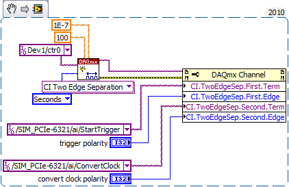
Conversion rates for simultaneous data acquisition
I use a Mech multifunction data acquisition. / s/SMU-6366. The maximum sampling frequency for the analog inputs is 2 MHz. Is the time of actual conversion of CDA always 0.5µs, or t - it change with the evolution of the sampling frequency? Can I set the time of the conversion? Reading, looks with peripheral multiplex, you can set convert it clock and the sample separately clock. What is with simultaneous data acquisition?
Hi Daniel K..
It is a big question. I wonder if you get any errant behaviour - your card is not up samples as you hope?
Here is some information that might help you:
Wikipedia: successive approximations ADC
I'm not sure exactly what happens, but dare a guess time digitizing ADC does not vary with the frequency of sampling. And it will also be more than 0.5 US - it is more than likely faster than that.
I hope this helps. Good luck with your application!
-
Control and simulation and data acquisition
Hello
I am applying to motor control in Labview. I'm sampling speed from DC engine in real time through an acquisition of data. (my sampling time is 1000 samples per second)
Then wrap speed as input to a Simulation (simulation and design of the order) and inside the loop simulation, I have a PID controller. The PID has the actual speed of the engine for the acquisition of data and the engine reference speed as input.
Reference engine speed comes from the generator of signals (control design and simulation-Simulation) and is a waveform.
My step in the engine size is 1000.
I am running this application real-time and drawing the reference signal and the motor real signals. I run into several problems with regard to the calendar.
1. when I change the size of the step of the simulation loop, the frequency of squares of reference also seems to change. For example. What step size = 1000, duration of pulse = 1 s. What step size = 100, pulse width = 0.1. (My pulse frequency is 1 Hz, Simulation clock - 10 kHz). How step size can affect the pulse width.
2. can you explain the relationship between the DAQ, the Simulation step size loop sampling time, Loop Simulation period.
3. If I want to collect different sets of data using sampling different hours, it's OK to change the sampling DAQ time without changing the size of the step of the simulation.
Would also like to emphasize that the DAQmx calendar under sample clock mode is placed in front of the simulation loop and the output is connected to the loop simulation.
Appreciate any help.
Hello
Maybe some screenshots of your code would help. Furthermore, what you have read your samples together with your DAQ screws?
(1) If you have a waveform, the output is specified as:
For example, if you change the size of the step of the simulation loop, you change the simulation time which are introduced into the signal generator and affecting the waveform that you see if you do not have a size quite small step to characterize the waveform that you generate.
(2) sampling DAQ rate is the speed at which samples are taken on the acquisition of card data itself. The size of the simulation step, help. "Specifies the interval between the time when the ODE Solver evaluates the model and updates the results of the model, in a few seconds." Simulation loop, still using, "Indicates the amount of time that elapses between two subsequent iterations of the loop of control & Simulation.". " "Step size determine the value of t that is introduced to the functions you use in the loop simulation while the loop simulation period controls simply to how fast you change the following t value. The sampling rate of DAQ hardware is a clock of completely separate hardware controlling the analogue-digital on the DAQ card converter so that you can get a deterministic dt between the samples being acquired.
(3) you can change the schedule for the acquisition of data, but you will need to restart each time the changes take effect. If you change the calendar of data acquisition and want your values to correlate with your simulation, you will need to change your size of step as well.
-Zach
-Zach
-
6361 versatile usb data acquisition does not automatically detect the SCXI chassis/accessories
versatile usb data acquisition 6361 will detect automatically SCXI chassis and accessories?
Hello kdCMC,
As far as I know that the SCXI-1600 USB Module is able to auto-detect SCXI Modules.
This is also mentioned on page 11 and 12 of the following SCXI to start document:
http://www.NI.com/PDF/manuals/373236m.PDFAll data (including USB-variants such as the NI USB-6361) have only a 68 pin shielded cable (IO) between the DAQ hardware and the SCXI chassis.
This cable does not auto-detect opportunities since it basically just "transfers analog and digital signals" between SCXI chassis and DAQ hardware.Is there a specific document that created the confusion on this subject?
-
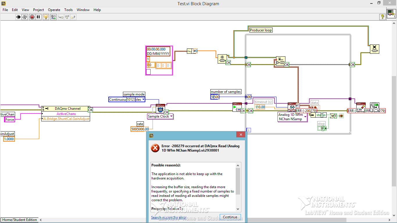
Code error-200279 for data acquisition
Hi all
I am trying to build a small program of data acquisition, but I get a 200279 error telling me to increase the buffertime. What I am doing wrong?
Andersson wrote:
No, you're right. I don't get the error, I turn off highlight execution.
It seems so. I did not understand why he would come with an error during the audit of the code with the bulb. It seems like what I discovered on www.ni, one can avoid the error of initialization of certain data for the chart.
Not sure if I got it 100% correct however. Here is the link:
http://digital.NI.com/public.nsf/allkb/A647A1BE3DA8336786257AAA0066B45B
I don't have any other loop in the installer. I'm sorry for the confusion with the name 'producer loop. It's the only loop in the code, I deleted the rest to refine the error.
Is the conclusion that the program is good? Or do I have to do something to remove the error?
The table has nothing to do with your error. It's strictly highlight execution.
When you configure a continuous sampling, start the collection of data at a given flow rate. It is so big a configuration of the buffer. There is an article that tells how much room it is exactly, but for the sake of argument, let's say 10 seconds worth of data. In normal execution, your code runs pretty quickly that she is able to empty the buffer as soon as the data are acquired. But when you enable execution of climax, your VI slows down to a crawl so that he can show that you step by step what is happening on each wire. Your data acquisition always occurs in the background. Execution of idle is to take much longer that data are acquired. Within one or more loop iterations, you have filled the buffer and get the error message.
You cannot use point culminating performance when you use a device of data acquisition in this way (or VISA ports either) where data are sent continuously at a speed that is independent of speed, the code is executed.
-
Problem of reliability data acquisition PXI-4071
Hello
I'm having a problem of reliability using my 4071 Pxi digitizer mode.
I have a number of tests that use the SMU-6363 (usually configured for DC) analog output to provide a stimulus for our own device, which has a number of a/d converters. We use the PXI system for calibration and testing.
1. I select a voltage ranging from tensions.
2. program the PXI-6363 to drive this tension
3 TIME about 10ms to settle. Note there no discrete capacitors or resistors in the circuit. Everything is parasitic and would generally be under the nF mark and less than 10 ohms
3. configure and Initiate() acquisition of data with the PXI-4071. In general, I use a sample rate of 1000 s/s and get about 30 samples (worth 30 ms). Activation is immediate and I used the default a queue time, 0, set the time and it doesn't seem to make a difference.
4. measure the voltage with the CDA. For debugging purposes I have sometimes made twice once before calling Initiate() and once after. The after is normal. The time required to measure the ADC is shorter than the acquisition time, but regardless of stimulation by the SMU-6363 is constant
5. extract the waveform.
6. the average waveform and compare the value of ADC measured by applying tolerances etc.
Here's the problem: it works well most of the time. But only 0.1% of the time (1 on an acquisition of 1000), I get 8-12 samples that are close to 0. It sounds like a problem of time settling (on the surface), but no matter the amount of wait time data, I always get this behavior. Not only that, but the tension before the call to Initiate() in height CDA, it always confirms that the motor voltage is already set to the programmed value. Nevertheless the acquisition presents near data 0.
So far our independent ADC always reports the expected before and during acquisition (100%) voltage. It's like the DMM input is disconnected during the acquisition during a period of time, because we have confirmed that the voltage is already present prior to the acquisition (component can). I have no errors the insider or FetchWaveForm calls. I still have all my samples. And 99.9% of the time that everything works as expected.
The DMM and ADC are connected to the same point and both are referenced to ground, and as I said before only the parasitic capacitance and resistance (cable). We use a matrix of switching (PXI-2530 (b) to make these connections. We almost always use 51/2 digits and 10V range for data acquisition.
Hello
I thought about it and was going to repost but am distracted.
The device with the ADC also has a mux and switches the mux to an internal node. It only switches when measuring and is open at other times. There is a race condition where the acquisition starts too early and maintains the acquisition after that the switch is open. Unfortunately I don't have the option to trigger.
I forgot the internal mux that I had designed the test years ago and I did some updates to improve the stability of the test. That's why we start the ADC measurement when acquiring.
I just added a routine to reject samples below a threshold
-
I get upgraded my laptop (HP for laptop - 15-r224tx) for Windows 10 but I can't find the driver for the controller of PCI Data Acquisition and Signal Processing. Please help me find the right one.
Thank you!
You are the very welcome.
It is the latest version of the W10 driver for this card model... see if this solves the problem, if you have not already installed this driver.
This package contains the installation package driver for the controller wireless LAN Realtek RTL8723BE/RTL8188EE in the laptop models running a supported operating system.
File name: sp72517.exe

Maybe you are looking for
-
Re: Qosmio G40 - different processor speeds in Device Manager
Just bought a G40-108 today and noticed something strange in Device Manager - speeds of the 2 nuclei differ.The first shows T7300 @2.00 GHz and the second is @2.40 GHz T7700.Although it isn't really a problem I am just intrigued as to why this is, ma
-
BUG strange when cropping after the rotation of the image!
Hello! When I want to edit an image like this:1. I turn at 90 or 180 or 270 degrees (any)2. I'm going to harvest it and try with None (without a default size)Sometimes the size of cropping to tremble when I want to change it with my fingers and it ha
-
HP G72 Broadcom wireless disconnect every hour
I have 2 computers in my room. HP pavilion all-in-one W7 (works fine) and a laptop HP G72 W7. My problem is the following: each time my wireless back on my laptop but never does on my all-in-one as well telling me this isn't my modem in the other roo
-
HP PHOTOSMART M425-PHOTOSMART ESSENTIAL-WINDOWS 8.1
I have a HP Photosmart M425 camera.When I had Windows XP, I used the PHOTOSMART ESSENTIAL software and I was able to download the audio recorded in photographs.Now, with Windows 8.1, I can no longer use PHOTOSMART ESSENTIAL.How can I do?Thank you.
-
Hello I am pleased indeed to be able to learn a lot from the thread on the topic "regular maintenance". I decided to start this thread on Malwarebytes' Anti-Malware (Free and paid versions) http://www.besttechie.net/MBAM/mbam-setup.exe I downloaded t