impedance NI 9401
Hello
I would like to acquire a PWM signal of 0/24V with the NI 9401.
I'm doing a voltage divider (R1 = 2.375kohm, R2 = 0.625kohm) to lower the PWM signal to 0/5V.
This two values of my resistance works only if the input channel of the 9401 impedance is greater than R2.
Is it OK to do it this way?
What is the input channels of the NI 9401 impedance?
Thank you
Hi Alexandra,.
Thanks for posting on the forum of National Instruments.
The input of the 9401 impedance is 47Kohm, so it should work with your voltage divider.
Kind regards
Tags: NI Hardware
Similar Questions
-
What is the impedance at audio Apple taken out?
What is the impedance at audio output of Apple jacks?
Interested in what devices? Audio output impedance values may differ. For example, modern article iMac features external ports and connectors - Apple Support (on iMac computers) might be of interest for the purposes of comparison.
-
Equium L20-197: what is the maximum impedance for microphone input
Can someone tell me what the maximum impedance is for the microphone to an Equium L20-197 standard input
I'm doing some recording on my laptop through the microphone input. I would like to know the maximum impedance entry is for Conexant AC-Link Audio version 6.14.10.590.
I do records and try different input methods, but I'm afraid to blow the whole sound card and the motherboard.I looked everywhere and I can't find out. If someone could help me please let me know.
Unfortunately, I also goggled and checked some sources of information but nothing
Did you ask to the authorized service provider in your country for advice or details?
Technicians usually have access to maintenance manuals that might provide details
Should more known as users just like you and me... -
I can measure the speed of the NI 9401 fan & cRIO 9075 under Scan Interface?
Hello
I am currently using OR 9401 & cRIO 9075 to develop a project, which is to control the CPU fans.
Since I have to communicate with other instruments by serial port, while I have a NI 9870 module to implement the instrument control.
I finished the part of control instrument under scan mode and would like to add the function of the fan speed reading.
Now, I wonder if there is a problem when I choose the Scan Interface to deverlop the program.
I found the following tutorial, he uses the FPGA interface to impement the acquisition of control and PWM frequency.
http://www.NI.com/white-paper/3230/en/
So if the function of the fan control only developed under an FPGA interface, I have to rewrite the control instrument part, seems to be a bit complicated...
You can use the hybrid mode.
http://digital.NI.com/public.nsf/allkb/0DB7FEF37C26AF85862575C400531690
-
Is a module able to drive a small 9401 (5amp) SSR with a 4-15 volt of entry?
You should consider using a buffer chip that can produce current, you need, like this. This will require a 5V supply, but it does the job.
-
I am using the IDW library to create a master by using the USB-6501. My problem is that the DAQmx write gives an error when it tries to use the 'Z' setting for high impedance. Are there workarounds for this?
6501 does not support high impedance state... inexpensive compared to high-performance and you have a low cost DIO.
Might be able to set the output to an entry, but there is still the internal pullup with that you will fight.
-
R series: compared to current output output impedance adaptation
Hello
I wonder about the output impedance specified for SMU-782xR and some other adapter module ike l 6581.
The specified output impedance is 50 ohms. To get the best signal integrity, it is imperative to adapt the impedance using a cable (transmission line) with a 0 hm 50 characteristic impedance and impedance of 50 ohm load.
But I don't understand how this is possible, because with a high level of 3.3 v, the output current proposed spindle must be 66 my. The current per output pin max 7821R is 4 my.
This FPGA offer 128 pins, so that the maximum total output current should be of 8.5 A, so 28 w. It's not realistic!
Could someone explain why outputs are 50 ohms?
And how do I adjust the line and the termination of employment?
Thank you and best regards,
Benoit Chantepie
Benedict,
After some thought, the concept of the output impedance is really not applicable outputs logical digital because they spend most of their time in the saturated States and time spent in the transitory States is not usually specified with the exception of the time limits.
What is your purchasing process is I would ignore the specification of output impedance. Watch the voltage and current limits. If those who do not meet your needs, consider external buffers. You can specify the buffer to meet the requirements of your testbed (including protection against defects if necessary) and to meet the specifications of the devices OR.
Lynn
-
I have a 9401 on a chassis 9188 module. What I want to do, is to have 3 DI, 1 and 1 PWM.
I thought I could put the DI 3 on channels 0,1,2. Output channel on 6 and a PWM using a digital channel 7 (-1). In this way, that they would be grouped with 1 4 input channels and the last 4 production by the manual.
The problem is I get a 201133 error that says that the device can be configured for input or output due to another task or directions when I try to run everything in the same vi. I can make the DI and DO tasks with no problem OR the PWM task without problem. I tried to book the tasks with the DAQmx control task VI as the suggested error, but not luck.
Is it possible to do all this on the 9401 at the same time?
Bryan
You won't be able to use 1 DI, 1, and up to 4 meter which are material tasks timed at the same time when you use a 9188: http://digital.ni.com/public.nsf/allkb/5E0B829E50ADE1BC86257AC50062B2D2?OpenDocument
In addition, you will need to make sure that you book the tasks to avoid the error of 201133 with the 9401: http://digital.ni.com/public.nsf/allkb/0495B7D5E2345DF386257730007EFD17
-Mike
-
Data acquisition using the USB-GPIB 82357 B interface for 4395 impedance Analyzer has:
Hi all
I tried to communicate Analyzer 4395A impedance with interface USB GPIB 82357 B using the command of expert keysight and Labview module tutorial. I couldn't able to find orders of SCPI (Standard for programmable Instruments orders) for 4395 A impedance Analyzer in the expert keysight command. Please help me on the subject of what are the other possibilities to acquire data from the Analyzer of impedance 4395 A using the interface USB GPIB 82357 B.? Is it possible to get LABVIEW plug & play drivers for USB-GPIB 82357 B interface? Our main goal is to control the parameters of impedance measurement and draw F vs IZI and theta vs F as well as get parameters of equivalent circuit on a PC with LABVIEW GUI.
Can't wait to help.
Hello!
I agree with 'heavy '. For more information on how to program a 3rd device contact the manufacturer because they have the knowledge. Unless there is already a LabVIEW driver for this device, you would have to implement that yourself and need information from the manufacturer.
Regarding your question if the GPIB-USB is unsuitable, it is quite easy to answer: If you want to communicate with a peripheral GPIB NI GPIB-USB can do this. But you would probably need a driver to use the GPIB of meaningful communication bus.
Best regards
Christoph
-
How to make accurate measurements at high impedance using NI USB DAQ 6343 in Labview
Hello. I use a DAQ 6343 for measurement of analog voltage on a signal of high impedance. I am aware that low impedance is recommended, but it is what is on my Board. I tried to measure several times to an A/D channel only, increasing the number of samples, sample rate reduction, and I find significant variations in all of the measures.
I wonder what is the best way to stabilize the A/D before taking a step on the way to analog input?
Thanks in advance for your help.
Jodi
Hi jschwatz100,
Here is a good link on ghost image, which talks about solutions for playback of a signal from a high impedance source:
http://digital.NI.com/public.nsf/allkb/73CB0FB296814E2286256FFD00028DDF?OpenDocument
I would recommend a circuit follower of simple tension of construction as a buffer between your signal source and data acquisition. Here is a Wikipedia article about it:
http://en.Wikipedia.org/wiki/Buffer_amplifier
I also recommend to maintain a ratio of 10:1 for your sample rate: Buffer Size(N Samples in Continuous Mode) and lowering/raising them both the same way.
DylanC
-
cDAQ-9178 & NI 9401 - ASM: incremental Rotary encoder works is not beyond a certain frequency
I use a chassis with a NI 9401 DIO module 9178 cDAQ. I'm trying to convert the output of a rotary incremental encoder ASM (in radians) to rpm.
Sensing head (PMIS4-20-50-240kHz-TTL24V-Z0-2M-S)
Snap ring (PMIR7N-20-50-M-20)
The encoder outputs 2500 pulses per rev (output 5V TTL). The maximum speed which will see the encoder is 2800 rpm, which is equivalent to 2800 RPM * 2500ppr/60 = 116,667.67 Hz in terms of frequency.
Since the NI 9401 of the operations specifications:
Maximum of the input signal switching frequency by the number of input channels, by channel
8 input channels... 9 MHz
4 input channels... 16 MHz
2 input channels... 30 MHzI use only 1 channel, so I'm assuming that the 9401 should be more than capable of handling the 116kHz which the ASM encoder is spit.
Everything works fine until about 2100 RPM (~ 87, 500 Hz) but then I begin to see a drop in rpm, followed by a flattened behavior, then a slight increase. But never more than 2100 RPM. Our test unit is inspected for other reasons at the moment so I can't produce a plot of the behavior (I can reupload later). I think this must be a matter of aliasing with the meter or something of the sort. I have a digital filter set in place with a minimum of 4.0E pulse width - 6. It is two times smaller than the width of minimum pulse at a frequency of 116kHz (0.0000085714). I don't think this should have an impact on the calculation.
Any suggestions? This value of RPM is essential to our application.
Thanks in advance,
-MB
brown_ktr wrote:
I have a digital filter set in place with a minimum of 4.0E pulse width - 6. It is two times smaller than the width of minimum pulse at a frequency of 116kHz (0.0000085714). I don't think this should have an impact on the calculation.
A 116 kHz frequency, the period is ~8.57 us, but the pulse width half duty cycle of 50%. Ascent/descent time factor, and it is quite possible that 4 US is too long for your encoder signal.
The shape of this graph supports this theory, if we consider that there is variation in the exact pulse of each encoder pulse width. The shortest pulse is ignored when the filter starts to kick in, and the speed of ROTATION increases pulses longer and longer are ignored then as well.
Try to decrease the minimum pulse of digital filter (US 2 or even 1 US) width and see how it goes.
Best regards
-
Encoder interfaced with NOR-9401
I bought a coder who has open collector and resistance to pull-up 3.3 kohm (TTL) logic output.
The encoder comes with four sons: power + 5V, GND, channel A and channel B. channel A and B are logic output.
Channel A and B are connected to the OID of NOR-9401 which is mounted on the cRIO.
A standard VI for encoder counting is used and compiled under the FPGA environment.
During the measurement, I have observed that there are number of significant loss in both directions encoder.
I don't think that there is a problem with VI like I used it several times on the encoders with output RS422.
Is there a problem with my current encoder with respect to its electrical interface with NOR-9401?
Thank you.
I don't think that there is a problem with pull-up resistance. Even if the digital IO ports have their own resistance to pull-up (usually of the order of 4.7kOhm - should be included in the manual), the power to be handled by the circuit of encoder output transistor is about 2mA. -Check your configuration for a correct connection GND. You must connect the encoder directly power GND to DGND to the printed circuit board Terminal.
-
NI 9401 pulse width measurement.
Hello
I'm not sure that I understand very well the pinout diagram. At the present time, I have a NI9401 in a NI 9172 chassis.
DIO0 and DIO1 are connected at the gates of light. I have an opto switch and I want to measure the pulse width when an object blocks passes through the slot. Can I use one of the other free entry of the for do?
The entries are DIO2, DIO4 and DIO5.
The other IO pins are used as triggers.
See you soon
K
Hi Kamilan,
If you explore in the measurement and Automation (MAX) and find your 9401, you can right click on the device and select "Pin of the device" which pulls up a window that says what features each pin on the device. For example, according to this document, DIO2 is PFI2 to THE CTR0 CTR0 B and FREQ OUT.
To answer your second question, do a right click on your device and create a new task for your 9401. "You should do an acquisition of signals" counter input "pulse width and select CTR 1 on your device. Once you do this, you can configure the parameters of your task and Max it will tell you where you need connect your signal source, which, for me, is DIO5.
I would like to know how it works for you, thank you!
-
9401 line direction configuration in LabView
I use NI 9401 to measure a quadraure encoder. and I want 9401 to output 5VDC to drive my encoder. How to set the direction of the line for each port on the 9401 in Labview?
Hi godspeed13
A quick search reveals thisgreat KB on the configuration of the 9401. Looks like you want to have a task of digital output and a task of entry of the meter. With DAQmx you do not expliclitly all the dirrection for your two ports, just configure tasks and book and start them in the proper order so that DAQmx can set up the device before beginning to all tasks.
I would be very careful when you use a line of digital output to feed an encoder. Each line of output is only really planned for 1-2 my current output.
Luke
-
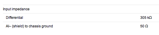
What is the input for NI9234 input impedance and where can I find it in the sheets in general?
If you scroll about 3/4 of the way through the online data sheet you will find this:
The differential input impedance is also the tab specifications of the NI 9234 product on the web site page of NOR.
Lynn
Maybe you are looking for
-
What is the difference b/w Google search Mozilla Start Page and search bar?
It is not a priority, I want just a general answer. I read that Google renew the license of the Google search bar on the Start Page of Mozilla Firefox, and it is where Mozilla makes 90% of its money, because it is a not-for-profit organization. I wan
-
I'm using mac os x version 10.7.4 and I try to update Firefox 3.5.5 version to the latest version. The Firefox icon in my doc still persists and leads me to the old version of Firefox. If it's supposed to happen?
-
Share the button on the preview does not work
Share the button on the preview does not work. I tried removing the toolbar, quit, and then restarting and reinstalling button, but no luck.
-
my windows live id wwas deleted how can I get it back?
I have another email address that I use to connect to other Web sites. I was not able to connect the other sites because my e-mail account has been deleted. How can I recover my email address?
-
error code 80070570 during installation KB2705219
Impossible to find a solution fo update error code 80070570 when you try to install KB2705219. I have windows vista 32 bit. Have you had recurrent problems of this type of update and you'd be grateful for any help.