NI 9234 input impedance
What is the input for NI9234 input impedance and where can I find it in the sheets in general?
If you scroll about 3/4 of the way through the online data sheet you will find this:
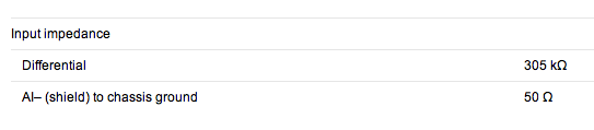
The differential input impedance is also the tab specifications of the NI 9234 product on the web site page of NOR.
Lynn
Tags: NI Hardware
Similar Questions
-
[visual studio c++] on the input impedance
If you look at the manual and specifications, this device supports only 1 M ohm input impedance.
-
Hello
I am trying to acquire an output of my DUT using the 6552 map, and the 6552 50 ohms default channel input impedance. It's pulling down of my output, so I want to change the impedance of 10K or 50K entry but I can't seem to do.
When I run the example of the input channel Impedance.vi and change to the 10K or 50K input impedance, it remains to 50 ohms. Similarly when I add the relevant property node (to change the input impedance) to my vi, remains at 50 ohms. I use the channel 0 as my string of acquisition and channels 1 to 7 as my production lines.
Any ideas?
Kind regards
Barry
Hey, Barry!
Can you post your code? Also, what version of NOR-HSDIO do you use?
Thank you
Keith Shapiro
National Instruments R & D
-
In differential Mode input impedance
Hi all
When I bought the USB-6212 card, I was impressed by the high input impedance of it - 10 GOhm.
This is indicated in the specifications, as in between HAVE + and AIGND.
So, what is the input under differential connection impedance?
Hi Navneet,
The question you have posted is actually a matter of multifunction data acquisition. You should post these questions in the Forums Multifunction DAQ. You will get much more quick answers to questions that are displayed in the correct forums.
The input impedance, in differential mode is a little less, then twice the impedance of the AI referenced to ground. What this means, is that he will be GOhms ~ 20 to 19. The actual value is not available, because it's such a high input impedance.
Best regards
Jonathan
-
NI USB - 6212 BNC analog input impedance matching
I just ordered a case NOR USB - 6212 BNC DAQ (should be delivered soon). I want to use to measure HV signals using a probe of high voltage of 1/1000 I have.
Now, datasheet of the probe (not a lot of info) says it has an impedance imput 100MOhm. I suppose that it consists of a simple resisitve divider, and if the ratio is 1/1000, I wait so to have a 99.9MOhm resistance in series with a 0.1MOhm resistance. However, the data sheet also specify that the probe is designed to be connected to an oscilloscope with an impedance of 1MOhm. As this input impedance is very low compared to the low value of the separator of resistance resistance, so I guess that the real resistance at the level of the sensor values 99.9MOhm and 0.11MOhm (to obtain the 0.99 and 0.1MOhm when it is connected to the oscilloscope for 1mW).
Therefore, given that the impedance of the USB-6212 according to the datasheet, the analog input is > 10GOhm, I expect to measure higher to true alternative voltages when connected to the acquisition of data from 10%. This assumption has a meaning?
What would be the best way to get around this? Do a calibration and correct the values acquired in LabVIEW code? Or should I add precision 1MOhm resistance at the same time to the acquisition of input data to decrease its resistance to entry to the value expected by the probe?
Thanks for your help!
Since you have a range of 1000: 1 I guess you also need bandwidth (I have a TEK 6015 A
 ), so you need based on the impedance input, a complex value, means he must not only watch but also the ability to input resistance (1 M). demarcation of the field probes have usually some elements of toppings to match the probe and the input scope. RTFM of the help of the probe
BUT a more serious point is that with your probe, you have a very high resistance. And if you look in the specification of the 6212 you will find on page 2 by mistake ppm in logarithmic scale graph! and even 100 k source impedance it not shown.
So I'm afraid that a simple 1 M on the DAQ entry can work if you're only measuring DC, and only if you use a channel on the acquisition of data. A workaround is an amplifier separate buffer with an impedance of good entry corresponding to the specification of your probe and a low output impedance.
-
question about the input impedance
Hello world
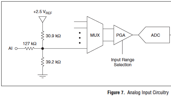
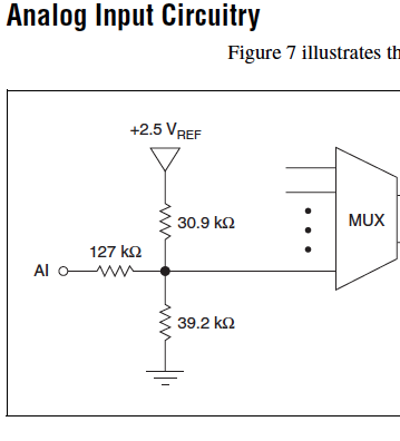
I tried to measure a voltage with internal impedance 10kohm source, and I connect to the source directly with the NI USB 6009. When the voltage source is 5.043V, the data recorded by labview are about 4.8V. I checked the manual of the USB-6009 case and found that the input circuit (see attachment). So I guess when the device was taken from data, it actually takes the data on the node of crossing and converted, then return with impedance numbers shown in the graph. That's why I'm given to me below that it should have been.
I was wondering is it possible to treat it, other than the calculation of return and convert it with correct impedance?
Kind regards
Jude
Hi Jude,.
you could use an op amp to boost your signal (1:1), one so reduce the impedance seen by the USB6009. You can also use some other DAQ hardware with a higher input impedance.
In the end, the conclusion is: you must choose your DAQ hardware according to the specifications of the signal source. You have selected the wrong hardware...
-
PCI 6221 analog input impedance?
Hello
I have a card PCI-6221, I know the impedance of an analogic imput?
Thank you.
Hello
As shown here, when the device is turned on, more than 10GOhm in parallel with 100pF
-
What is the analog input of the NI PCI-6229 impedance?
I am trying to determine the effect of a 12 K resistor that is in series with an analog input of an NI PCI-6229 data acquisition card. Resistance of 12K seems to be part of a RC filter. I have a 0-10 VDC source this supply circuit. What is the impedance of the analog input of the NI PCI-6229 data acquisition card? If it makes any difference, the analog input is connected in differential mode with a 180K resistor to Gnd AI.
Thank you
RWB
Hi, RWB,.
The input impedance is classified in the specifications 10 GOhm. So, the effect of your k 12 resistance should be relatively low. Take care!
-
Hello
The http://sine.ni.com/ds/app/doc/p/id/ds-260/lang/en datasheet speaks only of the voltage range to the analog input. I don't see anywhere else having the limit on the current information. I guess we have a range of current for the analog inputs. Could someone give the document for this?
Thank you
The input impedance is > 1E9 ohms. Of the law of Ohm and about 10 V input voltage range, you can calculate the current both input<10>
Lynn
-
Digitization and adaptation of impedance of the signal source entries
I'm trying to measure the voltage difference and the time between the two entrances of a USB-5132 digitizer. The switching interval that I try to capture is ~ 150uS and I intend to acquire ~ 25K samples (50MS/s for 500, although it is an overdose of sampling frequency). The digitizer is 1 M ohms entered and I wanted to use the 100 SMA 50 ohm cables to connect to the source of the signals which in addition to several kohm impedance. My knowledge of RF is low and I am concerned about the impedance matching between the digitizer inputs, impedance source and wiring. What kind of considerations to I need to avoid degrading the signal? The switching signal is pulse-like and is rich in harmonics and on a sample of 500K samples/s scope is represented accurately. Should what kind of considerations I do about the impedance?
Hi William,.
There will be some problems if you try to use a source that has an impedance of several kohms. You will probably get the reflections of signals. What is the source of your signal has several kohm impedance? I'd take a peek through the following article Developer area that describes some of the considerations when it comes from impedance matching. Specifically, I would check the last section corresponding resistive. This should give you a better idea of what to worry about your application.
http://zone.NI.com/DevZone/CDA/tut/p/ID/3475#toc4
Here are also a couple more developer area articles that you might be interested in what concerns your situation.
http://zone.NI.com/DevZone/CDA/tut/p/ID/5779
http://zone.NI.com/DevZone/CDA/tut/p/ID/2892
Chris W
-
the entry on Tektroniks DMM4040 high impedance value
I use a Tektroniks DMM4040 with itself to record data of voltage. When the digital multimeter is used in manual mode, there is an option for a high (> 10 GOhm) input impedance during the measurement of the potential.
This option can be introduced on the market when the multimeter is controlled by SE?
Thanks in advance!
Marc
-
SMU-4304 causing the ripple on the input signal?
I have an SMU-1082 chassis that contains a high-6341 and a PXI-4304 module. To check my code, I have connected the analog input (channel 0) of the 4304 to the digital output (PFI 12) of the 6341. My program VI shows a ripple of Vpp 0.2 on the analog input that I'm not using a scope.
The wiring is SMU-6341 [12 PFI, DGND]-> SCB - 68 a,--> TB-4304 [AI0 +, -]-> SMU-4304
I have attached photos of the verses reach the graphical VI. The scope is the AI0 + AI0-terminals and the TB-4304.
Y at - it a supplement on the ground that I should use, or is - this normal for the-4304 to add the ripple?
Thank you
Ron
Short answer, is that there is nothing wrong with what you see.
You have connected a digital output signal low impedance to a digitizer analog high input impedance. Since a digital signal is essentially a square of variable in time wave and square wave have edges of transition that contain information of very high frequency, you will almost always see a form of "ripple" (see animation synthesis of fourier of a signal square from this Wikipedia page ). Thus, a digital output signal is more concerned with the synchronization and the upgrade to be a square wave perfect.
In addition, you can see additional "ripple" because of differences between the SMU-4304 and the noculars that you have demonstrated. the noculars can be a combination of a bandwidth of upper entrance (which can come from various sources like low sampling frequency on the 4304 which would result in a higher frequency of information recorded by the noculars for smoother transitions to research) and, possibly, a lower input impedance (causing less, if any, the reflection of signal which would cause the ringing of the signal).
-
NEITHER 9265 can supply high impedance
Hi, we use a USB NI 9265 to send a current with a continuous noise superimposed in a load current.
The current is of the order of only 100 microamps.
It works fine for about 2K - 10K Ohm loads as long as we do not exceed compliance 12VDC voltage.
When attempting to conduct the current in a high-impedance device as a unit of isolation for stimulus grass Instruments PSIU6 we have a problem.
The visualization of the blood at the entrance to this unit of isolation on an oscilloscope, indicates that the NI 9265 is show something that causes tension sit at 13 volts and we cannot change that.
I suspect that the very high the segregation unit input impedance is too high for the 9265 to manage.
Someone else has experience with this current USB NI 9265 amplifier?
Thank you
What is the impedance of the PSIU6 entry?
Assumming 100uA and a voltage of 12V compliance, max load can be 120Kohm. Even less if you drive 100 AU.
-AK2DM
-
Issues of analog input DAQ-6008, voltage not zero to pin when you are offline
I use the 6008 NOR-DAQ to produce a series of tensions and then read a sense resistor using the analog input (CSR). I noticed that my analog input gives me 1.3 V, when I probe it (compared to the mass of the device), when it is completely disconnected. This changes the reading to give me a different measure of sense than expected resistance.
Why is my pin for analog input non-zero? Any help would be appreciated. Thank you!
The 1.3 V is expected. The USB-6008-and-6009 case have the strangest input of the world circuit. The input impedance is approximately 144000 ohms terminated in 1.4 V. check the document User Guide and specifications.
Lynn
-
Cut-off for the 6008 analog input voltage
I am using the analog inputs NI USB-6008. The specification says they have a 144 k ohms input impedance. But it does not say what is the cut-off voltage. If you leave a disconnected and measure the voltage you will get 1.4 volts. So I guess it's the cut-off voltage, but it is not spec'd.
Someone agree that these Amnesty International isn't terminatied by 144 k - ohms to 1.4V? Is this in the documentation somewhere?
Figure 7 on page 16 of the NI USB-6008/6009 User Guide and specifications shows the strange input of this unit circuit.
Lynn
Maybe you are looking for
-
storage iCloud notifications must stop
Storage in my "iCloud" approximates completely used. It is very good. Is not very well what * program popping up every hour to tell me about it. I need to tell her to stop for advising me. This is not currently an option in settings, then it shou
-
With the help of iDrive Google Drive on osx?
Hi guys,. I like very much the fact that iCloud capable apps to synchronize their data in the cloud. The ease with which you can store data in the cloud handpicked is also apparent. There is one thing on which I am not so thrilled. You can't control
-
Firefox is not connect to internet unless the reboot
So, recently, I had a problem with Firefox does not connect to internet unless I quit and reopen the app.It happens like this:-J' open Firefox and it works;-I lose the internet connection (for example, I turn off my wifi, or my laptop goes to sleep);
-
I had two sources of camera recording the same audio - I want to be able to do is use mulitcam SYNCHRONIZE the audio and video at the same time and be able to use the two clips simultaneously in a video - multicam - how can we use the TWO videos? In
-
Reset Toshiba e-store account - 32856
I bought this camera and when I try to access the virtual toshiba place request to do an update. Once I did a white screen appeared and I can't use it. What can I do? My personal account is 32856. Thanks for the tips