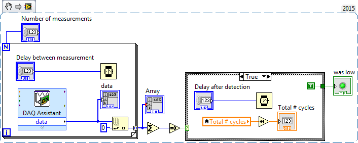
index of Digial waveform on digital lines
I have trouble stripping the lines separated a 9401 cdaq map DAQ-9172 chassis. I have attached the vi I use and can get the separate line to view a chart, but cannot strip each output. I want to step through each line a dac and use your unique on the analog waveform for the frequency of each.
bassinbc wrote:
I use 8.6. Attached is a table 1 d with each anlaolg entry deleted. The chart shows each channel separately. I don't see why you need to send a chart, a table 2D.
-What are you working now?
The code you posted this time is much more complicated than what you have posted before, and your chart is configured differently. Until you come to have a picture of wave shape of double type that sent you in an array of 1 d of doubles. The table that deals like multiple points on a single parcel.
In VI you just attach, you send a table 1 d of waveforms, which is a multiple of the wave forms (each element of the 1 d array) with 1 or more points per waveform (the Bay of Y inside the waveform data type). Curiously, the context-sensitive help for the waveform graph does not mention a table 1 d of waveforms, just a data type of waveform. However, the charts.vi found in the finder of the example shows this and other options. I would recommend the example of Charts.VI to see all opening variations.
Tags: NI Software
Similar Questions
-
SMU-6556 - how to control the rise in digital lines (hsdio) time
Hello
Is it possible to control the rise in digital lines SMU-6556 time?
Even in a low frequency 10 kHz signal rise time is 2ns.
TKS,
Hello engfpe,
The SMU-6556 is a 50 Ohm system, which means that the output is source series finished to be 50 Ohms and all our cables and accessories are 50 Ohms. With this configuration, regardless of the flow of data, you should have a clean edge up or down, regardless of the data rate. The quality of the production (edge up or down) on your device is related to the adaptation of impedance of your cables.
The SMU-6556 cannot adjust the speed of scanning by itself. However, you can insert simple passive components to do it for you. I have attached below the images. The first is a diagram showing a way to slow down the edge. The second is the a waveform simulation showing the rate of original edge before it slows down and the edge of idle. This simulation is not the SMU-6556 but rather a generic digital output for concept. In the schema that R1 is set on 34 Ohms because U1.8 has the 16 additional Ohms on the inside. TL1 is the output of 50 ohms simulating the cable on the SMU-6556. R2, R3, and C1 are components, you can insert after the SMU-6556 twist before moving your device/cable. In this configuration from cable to your device is TL2 which is also 50 ohm, but it could be another impedance in which case you would change R3 to match.
You can see in the attached images, you can slow down significantly the edge with this configuration by altering the C1. I hope this helps.
-
Default settings for digital lines? USB-6009
Hi all
I use the digital lines on my USB-6009 to control normally open SSRs. When I turn on the system, I would like to have the digital lines on the USB-6009 case to automatically configure themselves to be output digital lines put in position "Low", so I don't spend on my SSRs until I gave the command. Is there a way to do this?
Thank you.
Cannot set default on 600 x Renault States, unfortunately.
Do a genius on the hardware side, knowing the lines are pulled high on the acquisition of data is initialized. and if certain combinations of outputs produced a dangerous situation, you must stop to happen in hardware. Good practice to do so anyway.
Another option is to use an analog output, those can pump a little more power than otherwise to 1V, and do what is usually not sufficient to turn of SSRs.
-
DAQmx Read simultaneous calls on the same digital line
Hi all
I use v10.0 LV 32-bit on Windows 7.
I use DAQmx Read (in a task) to check the value of a digital line. Is it OK to do this in two different locations in a program at the same time for the same digital line? Or I have to put a wrapper around reading to force operations to be sequential?
Thank you
ZolaWhen you need to expose the capabilities of resources to multiple areas within a project (expand the scope of a resource) it is common to wrap the resource in an Action engine to encapsulate the resource functions. See here for an example of a 'Module on resources' material and a discussion animated about how this code help development construction and avoid resource conflicts. If you have not read famous nugget again – he of Ben is a link in my tag "Required_Reading".
Or more directly. Yes, you should encapsulate these readings DAQ to avoid suspended
-
A SIMPLE change: reading a digital line instead of 4 ports
Hello
I found this application (see sippet) who read four digital ports and then add them in table 1 + and every time the sum of the array is 0.
I'll just check on a digital line. When I change the Assistans DAQ to digtial line entry port, it turns into a Boolean value. But how can I change the settings I only compare the line including propely is 1 or 0. ?
Thanks in advance.
If I understand your question, you can replace only the elements of the array add and equal to 0 with just one or elements of the array.
-
Hello!
My problem appeared when I tried to update my traditional NOR-DAQ legacy code to DAQmx.
I use 2 meter (meter 5 and 7 meter) on PCI-6602, to generate trains of pulses, as well as the lines of e/s digital port 0 (the form lines from 0 to 7). What I do in my request, it's that I'm starting to generate the pulse train on the output of 2 meters and after that I play with the State of digital lines.
Traditional, it was no problem to use the meters and digital lines at the same time, everything went perfectly, but in DAQmx, is not possible.
What's happening: I start generating train of pulses on the output of counters, no errors, but when I try to change the State of a line of digital port the generation of the pulse train is stopped. What happens when I start the task associated with the digital way.
My question is: is it possible to create a channel on digital lines without changing the channels created for meters?
Another thing that I managed to do with the panels 'Measurement and Automation Explorer' and Test for PCI-6602, is basically the same thing, I generate trains of pulses on the output of the 7 meter and try to start a job on the digital line, but I get an error:
"Error-200022 occurred in test Panel.
Possible reasons:
Measurements: Resource requested by this task has already been reserved by another task.
Device: Dev4
"Terminal: PFI8.On the contrary if I use the counter 0 or a counter 1 to generate trains of pulses I encounter the same problem.
What resources are used by 2 to 7 of the PCI-6602 card counters and the counters to 0 and 1 do not use?
Thanks in advance for any answer!
Ciprian
After doing some real tests on this device, I found that it is a normal behavior for the jury of 6602. This is because when you start a task digital all 32 lines are configured for digital i/o, so it replaces your meter operation. The article below the link explains a little more on this subject. You must start the digital task before the task of counter to use the features of both in your program.
2 meter and above will not work correctly when you perform digital i/o on NI 6601 or 6602
http://digital.NI.com/public.nsf/allkb/43F71527765EEC3886256E93006CD00C?OpenDocument
-
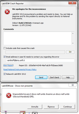
Crash when selecting digital lines
Today, I tried to get the routing in the DAQmx card work. While I was first with an external connector to wire a counter in a PFI line, I thought to this internal routing. He worked and had to restart the pc to check if she was still working after restart.
Since the restart, LV 2012 guard crashing to the VI, see:
The culprit is the selector to select digital output lines for the DAQmx, but I can't find out why and also I can not solve. First of all, I had a list of the output lines and selected bonds. Now, the list is empty. When you select the drop, after a few clicks LV crashes. However, I do not understand that it makes account, it cannot find the disc hard \Device\Harddisk\DR1. I have only one hard disk in the system and that one works properly.
Lvlog.txt shows the error has to do with the transact.cpp (1454):
15:48:41.014 03/06/2013
Coolish 0xAC17A51A: text hidden after the mouse-><27>
e:\builds\penguin\labview\branches\2012patch\dev\source\editor\transact.cpp(1454): coolish 0xAC17A51A: hiding the text after the mouse-><27>
Minidump ID: ab53c62e-6dc7-4702-b477-645b916e4663
$Id: //labview/branches/2012patch/dev/source/editor/transact.cpp#1 $Attached are the screws of the project and the log files.
I tried the following:
-reset the devices in MAX
-reset the configuration data in MAX
-restart the computer
-deleted the cache of compiled objects
LabVIEW plug is:
####
#Date: sea 6 March 2013 15:44:44
#OSName: Windows 7 Professional Service Pack 1
#OSVers: 6.1
#OSBuild: 7601
#AppName: LabVIEW
#Version: 12.0f3 32-bit
#AppKind: FDS
#AppModDate: 04/10/2012 15:12 GMT
Base address of #LabVIEW: 0x00400000MAX version: 5.3.1
The questions I have are:
-takes down also to when you create a constant for the Digital lines create you Channel.vi in the DDS - output Config.vi?
-does anyone have any suggestions on what I might try?
Hello
I can create the DAQmx constant without problem and also to display the digital lines available with DAQ hardware that I have connected to my PC.
Have you tried to create the constant directly with Create > Constant for input lines?
You can create the DAQmx constant in a blank VI? You can insert a control name on the sign DAQmx front of the modern > range of I/O?
As I can not reproduce the crash, it seems that something has been corrupted in your installation. You can try to repair the DAQmx and LabVIEW software and in the cases where it does not work you can try to reinstall the software.
Bye,.
Licia
-
where can I find 'write to Digital Line.vi.
Hello
I have a few programs that run in Labview 7, installed in a machine. I want to migrate them in Labview 2011 installed in a new computer. After that I open the program in 2011, it retains the search all files and stop asking the screws 'write to Digital Line.vi', 'AO Update Channel.vi', 'update AO (value on the scale) channel ". I Googled it and some said I should install the drivers. I downloaded and installed the driver NOR-DAQmx 9.6.1, but there aren't always find these screws anyway to solve these problems? Thank you very much.
If you pick up the VI and finds you, all you need to do is save your VI. Remember the location the next time you open it.
-
Written for several digital lines separated by commas
Hello people,
I use a USB-6009 box and want to write several digital lines created in the style, separated by commas:
error = DAQmxCreateDOChan(taskSelHead,"dev3/port0/line0,dev3/port0/line6","",DAQmx_Val_ChanPerLine);
When I try to write in this channel I do
uInt8 data [8] = {d1, 0, 0, 0, 0, 0, d2, 0}; with d1 and d2 that represents 0 or 1, which bits I want to get written
int error = DAQmxWriteDigitalLines (taskSelectFilter, 1, 1, 10, DAQmx_Val_GroupByChannel, data, NULL, NULL);
The result is, this only $line0 is updated, lin6 rest 0.
I also tried DAQmxWriteDigitalU8 with the same effect.
Can anyone help?
Thanks in advance,
Michael
Hi Michael,
you have defined two dig.out channels in your task: line 0 and line 6. So, when you write an array of string values, d1 Gets the mapping to your line 0 straight - but line 6 still receives a zero!
Have you tried to set data uInt8 [2] = {d1, d2}?
Best regards
Sebastian -
I was wondering if it would be nice to remove the BVRP Software program to detect digital lines from my windows vista system. It comes up that there is a problem with compatiablity when I restart count it. I don't remember installing this and don't know if it is a program that was installed when I got the computer. I have the digital line detect and the netwaiting programs of BVRP software, inc. Any help would be greatly appreciated as I tried to speed up the computer. Thanks in advance for any help.
brighteyes4291
BVRP software modem because their phone tools are often bundled with a new computer/modem with a built-in modem. You can safely uninstall both programs you mention, but I'm not sure you'll see changes of speed on the computer. The digital detection program is there to inform you if you connect your analogue telephone modem to a digital telephone line. This can damage an analog modem.
HAL
--
HAL Hostetler, TCE
Engineer senior/UPDATED--MS MVP-Print/Imaging - WA7BGX
www.kvoa.com - KVOA television, Tucson, AZ.
Live Hot Licks - www.badnewsbluesband.com -
Microsoft Defender is blocking the start of digital line (DLG.exe) by Avanquest Software detection
Hello
I use professional Vista as the operating system of my laptop. Recently - specifically, since having started using COMCAST (cable TELEVISION) - provided internet service - I started having a condition of starting Windows in which Windows Defender gives notice it blocks a program from starting. IDs Defender this program as: DLG.exe (Digital Line Detection), an application digitally signed by Avanquest Software. He seems to have been (manufacturer?) installed in my computer (IBM Thinkpad/Lenovo) to 14/03/2008. Path: C:\program files line detect\DLG.exe. Since this notification Defender is new to me, please advise me - if you can - if it is a plu program allowed to run, its function, or if I should simmply withdraw from start-up operations to eliminate the constant defender notifications.
Thank you for your consideration and support. Feel free to contact me if you need additional details.
With the best regards,.
John
DLG.exe is trying to detect if the telephone modem from your computer is connected to a digital line, for example a PABX . It is safe to remove it from startup. Boulder computer Maven
Most Microsoft Valuable Professional -
Outbreak of several digital lines of a single window using PCI 6353
Hello
I use a PCI 6353 to control a laser for a PIV system. The laser requires 4 pulses (F1, F2, T1, T2) on different channels. It would be easy using 4 counters on the Board, but I also need to trigger the camera. The card has a lot of output digital, so I thought I could use 2 meters and four digital outputs.
I thought that, by setting the pulse counter from 0 at a time duration between F1 and T1 and triggering a rising edge and T1 F1 a front down using output internal), I would be able to solve the problem. However, the system I cannot trigger the two lines of the same internal output. I don't know why. I have attached two vi, one for a single channel that works very well and the other with two channels. I am also attaching a diagram of approximate time of my proposed solution.
I am not absolutely put on this format, so if this is not possible and you have another solution, please let me know. Accuracy is the key here, the widths of pulse being about 1 microsecond and the intervals between F1 and Q1 being approximately 10 microseconds, so I think the hardware timing is essential. However, I'm not quite clear on interact it with the digital pulses and counters.
Kind regards
Joe
Hey Joe,
All the lines that you want to use for quick time ARE on the 6353 must be in the same spot. Unfortunately, you can't start or clock several lines independently.
That said, I think that the simplest solution would be to simply create a waveform suitable for generating all 6 signals with. You should be able to clock up to 10 MHz, which gives you 100 ns resolution. If you need 1 us resolution, then you could get by synchronizing the c to 1 Mhz. While you could technically use a combination of counters and to get what you need, it should not be necessary in your case. All you need is a single task with the waveform appropriate to generate your desired signals.
Best regards
-
Definition of the State of a digital line indefinitely
First off, I don't know if I approach this problem in the right way, so feel free to point me in another direction.
What I'm trying to implement: I use the NI USB 6251, which is connected to a personalized card. The relevant part is that one of the devices with the fact that I'm communicating is a chip that uses the C-BUS Protocol. There is a CDATA and RDATA line to read/write the values of registers (8-bit), a line CLK to these input/output values of clock and line CSN (chip select) which must be removed down whenever data is written into the chip.
My attempt at implementation:
I use a task for the CDATA/RDATA + CLK lines. I connect the CLK by setting the ExportSignals.SampleClockOutputTerminal value to the physical address of the CLK line. Then, I use a DigitalChannel + a writer to write in the CDATA.
I have a separate task for the CSN, and this is the part that I'm not very sure. This line must be pulled down in any communication with the chip. So what I basically is this:
            chipSelectWriter.WriteSingleSampleSingleLine (true, false);

            commWriter.WriteWaveform (true, waveform);

            chipSelectWriter.WriteSingleSampleSingleLine (true, true);
What I do know, is that this really pulls the bass line long enough so that the waveform to write, or if he pulls it is low for a single sample and then returns.
My first instinct was to use the DataActiveEventOutputTerminal property, but because these lines are connected to the lines "PFI" (forgive my lack of understanding of the terminology), data acquisition informs me that this feature is not supported for PFI lines.
What would be the right way to program this scenario. Can you tell me some examples? I can post the code if necessary.
I discovered through more tests that the above code does what I want to do, so consider this issue resolved.
-
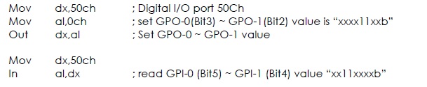
NIMAX, how to create a digital line for address GPIO
Please, let me ask you a question about IO port address the NIMAX and PC.
I have an industrial PC with available GPIO ports.
The example of reading and writing address was broadcast on the underside.
address port number is 50Ch.
How can I create the line digital 50Ch in the NOT-MAX.
Thanks for any suggestions.
MAX is useful for the hardware configuration of OR. Since this GPIO is not a product, NOR it will be not configurable in MAX.
-
Table of waveform and digital signal 2
Hello
I need to see 2 or more digital graphic USB6008 of waveform input signal, but each signal must be different offset, it is possible?
Just add a constant offset to the second signal between the Boolean value to (0,1) and the fiber node.
Lynn
Maybe you are looking for
-
Hard drives, Interface regularly ejected
Hi people, Since the update to the latest El Capitan (10.11.6), all my external drives and the interface is constantly ejected. want to go back to the previous version, but the ejected disc always has this version. Options? BOE
-
Cannot download addon, Mozilla server is down
Correct your servers. It says "connection failed" when I try to install. I tried to download with free download manager too, it says "server error". https://addons.Mozilla.org/en-us/Firefox/addon/copy-link-text-4750/?src=userprofile It's the newspape
-
Why does not my cd on my HP PAVILLION 305 computer tray?
We burned before cds on my computer, but even, now the drawer will not open to insert the cd. What can I do to fix this? I hear clicking on and light flashes as it is tempting, but nothing happens.
-
Windows Vista doesn't let me see the list of downloadable updates.
Hello gentlemen and ladies. Bing and Google couldn't help me so I try my luck here. Windows Update has this strange bug or glitch, it tells me that there are updates available, but if I want to see what updates nothing appears in this list, but it do
-
SIM card and the mobile broadband card
I have doubts on the WWAN card, I do not use the external for internet modem because I prefer internal modem please give solution on WWAN card, I use my L502x xps and my network 10W is Intel Centrino Advanced - N 6230 and there is a slot for SIM unde