Input analog frequency on DAQmx measurement
I have an analog impulse (amplitude varies) connected to my USB-6212 DAQmx device. I am looking for a way to measure the frequency of the signal. So far, I have found no method DAQmx supported to achieve this. I'm coding in LabVIEW and the only way I found to do this is by writing my own code for the analysis of signals amplitudes to determine the level of half-max to find fronts and edges in order to count the pulses to calculate the frequency. Someone please tell me there is a better way. I need help on this one guys.
With an analog capture, you can try the function extract your unique information on the Signal Processing > range of measures of waveform. There are also Express your measures VI.
Tags: NI Hardware
Similar Questions
-
NEITHER USB-6343: erratic low frequency 1 counter measures
Dear members,
I'm looking for help with a measure of low frequency counter. I tried to make it work for a week or two, but I keep getting erratic measures. It will read the rpm properly for a second or two and then it will give a ridiculous value on the order of 10,000 times the correct value. I can not get a constant value.
I use a DAQ series X NI USB-6343 multifunction with Geartooth Honeywell GTN1A111 sensor. I enclose a sketch of the wiring configuration. I think that it is correct. Sensor output to the door of the meter.
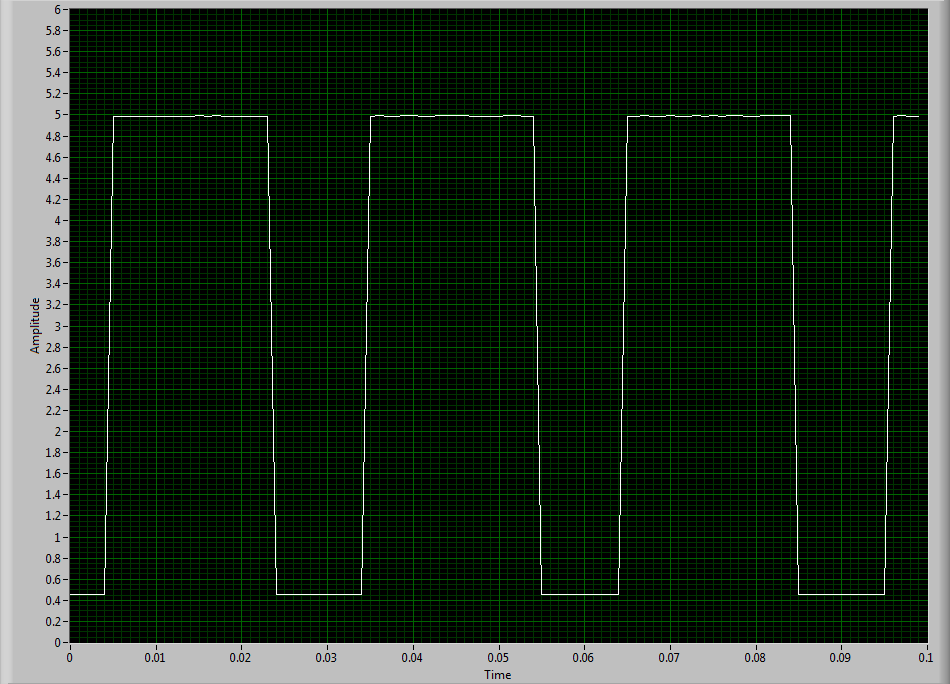
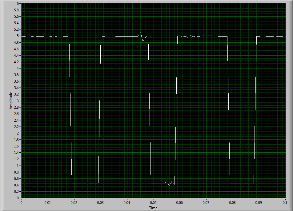
To try to solve this problem, I hooked the sensor to an analog input channel to make sure that I was getting a TTL signal by sensor. I noticed every once in a while I'd see a glitch of little noise in the signal and I guess that's what is causing my problem with the meter. I inserted two waveforms of the sensor signal (one with the clean signal) and the other with the glitch of noise. My understanding of a TTL signal meter channel will examine LO voltage when it is below 0.8V and HI when it is larger than 3.8V. So I really do not understand why these little glitches could be the cause of the problem because they are well below and above 0.8V and 3.8V, respectively. I think that the noise comes from a frequency converter used to drive the engine. I tried the system as much as possible of the Earth.
I guess I'm looking for another approach. I could potentially use a digital filter to help with noise? The glitch is in fact the problem or I forgot something. The VI in question is attached.
Thanks in advance,
Mike
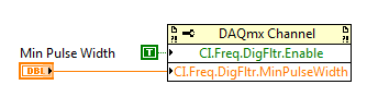
Have you tried to set up a digital filter yet? Obviously the seeds are collected as an additional transition (the method of low frequency counter 1 measure the period and then reverse, so a short glitch would record as a very high frequency).
You can enable the digital filter with the following property node:
Min pulse width is guaranteed pulse past the filter, so it should be low enough for the real signal is guaranteed to pass through (but high enough so that the glitch is always rejected).
Best regards
-
input analog trigger on the door of the meter to measure the frequency of generation
Hello
I want to measure a frequency on the analog input, but it doesn't seem to work.
I'm trying to work with DAQmx with the use of the ansi c standard.
The first step, I've done was acquiring information on the analog input. With the use of a simulated device, it shows a sine wave on the entry.
My next step is to generate a trigger for the meter signal, but this doesn't seem to work.
I don't see how it is possible to connect the trigger on the entrance to the analog meter.
For the creation of the analog input and relaxation, I use the following code:
DAQmxErrChk (DAQmxCreateTask("",&taskHandle));
DAQmxErrChk (DAQmxCreateAIVoltageChan(taskHandle,"Dev1/ai0","",DAQmx_Val_Cfg_Default,-3.0,3.0,DAQmx_Val_Volts,NULL));
DAQmxErrChk (DAQmxCfgSampClkTiming(taskHandle,"",10000.0,DAQmx_Val_Rising,DAQmx_Val_FiniteSamps,1000));DAQmxErrChk (DAQmxCfgAnlgEdgeStartTrig (taskHandle, "Dev1/ai0 ', DAQmx_Val_RisingSlope, 0 '"));
For the creation of the meter, I use the following code:
DAQmxErrChk (DAQmxCreateCIFreqChan (taskHandle1, "Dev1/ctr1", "", 1 January 2000, DAQmx_Val_Hz, DAQmx_Val_Rising, DAQmx_Val_LowFreq1Ctr, 1, 4, ""
 );)
);)I hope someone could give me a hint.
I also tried the examples that come with DAQmx but well I know this are only examples to counter with the help of the digital inputs.
Thanks in advance.
Hello
You must use the exit event of comparison at the entrance of the meter. Change this property after the configuration string function.
DAQmxSetChanAttribute (taskHandle1, "", DAQmx_CI_Freq_Term, Dev1/AnalogComparisonEvent);
Kind regards
Bottom
-
Magnetic sensor to the top of analog frequency AC for Turbine flow meter measurement
Hello!!
I use the following hardware configuration to measure a flow meter flow turbine.
Material: 1000 SCXI Chassis
SCXI 1102 voltage input module
SCXI-1303 terminal connection block
Flowmeter: output signal is the frequency of the alternating current (30mv peak-to-peak). Sensor is a magnetic sensor type.
I tried to convert the signal of output voltage in the area of frequency using the FFT, but I get the wrong data.
I wonder if anyone can suggest good troubleshooting techniques so that I can understand what is mess up my position or my technique of measurement in labview itself will not completely? (From my understanding I think that I can measure the frequency of the ac voltage signal generated by the sensor of the FFT. By measuring the frequency I can calculate the water flow)
I am aware that a potential cause might be the ground loop in the system. The signal is based solely on the SCXI-1102 with factory default bias and pullup resistior network. I see no other reason reading wrong or fault in my measurment. Also the flowmter is brand new and there is no risk of damage to the sensor.
I'm sorry if I'm missing out on any important detail to answer that I am relatively new on the techniques of data acquisition.
Thank you
Concerning
Aditya
It's conditioning of signals... and that's what you want to do, so it's not so far

And if your signal about 30mV Ridge to Ridge, it fits perfectly in the beach of crete to 200mV Ridge... I wouldn't say no need of amplification... the + 100mV is not a minimum of signal, this is the maximum signal in this range
Hang it up, take a measurement in single channel mode with one all 10kSPS sample rate take 100ms (1000points) and feed in single tone detection...
display with a graph of signal, stop the vi, in the rigth diagram, click the graph icon and create a constant, save that in a vi and post here if you need help in signal processing
-
Helps with 7852R input analog voltage measurement
Hello
I'm trying to measure three signals of tension off a QPD, the three signals are connected to the IA the SCB - 68 and then I used the example of vi to acquire analog inputs with FPGA R in the finder of the example. However, I make a range of very large numbers. I don't know how to convert these volts or what are these numbers, units... etc.
Any help with this, please?
Thank you
Hi Biochemist_MU
Please take a look at the forum post FPGA of analog input and output scale. It deals with the scaling of the R-series cards.
Hope this helps and let us know if you have any other questions.
-
measurement of analog frequency with PCI or USB
I want to measure the frequency of a square wave 0 - 5V from zero to about 4 kHz permanently. I have to record the waveform, only get the frequency. The material at my disposal include:
(1) PCI-MIO-16
(2) 6062E DAQCard
(3) USB-6218
If none of these devices can do this? This seems to be a very common task, why can't I find the perfect example to do so. I'm not having any luck with the DAQ assistant. Can someone tell me a simple example?
You can also read the following link:
And look at the examples in the zip here
-
Measurement of low-cost input analog (4-20mA) with data acquisition
Hello
I would like to have a very low cost measurement system loop which I can plug in my laptop current:
I have a load, which is connected to a circuit of air conditioning/signal booster, which output a 4-20mA. I want to measure this current loop signal.
An idea for the lowest cost system? I think that the most NOR DAQ are too expensive and too exaggerated.
I have LabVIEW.
Use of remote sensing current low-value resistance, then measure the fall of voltage through it with the help of an acquisition of data 6008/6009? They have about $150.
You will probably need to amplify current-sense with a MAX4372 or similar resistance to achieve a result that allows you to use a reasonable scale on data acquisition. I measure the current through our products in almost all of our equipment to test in this way. The size of the resistance of meaning as a result. The 6008 is accurate enough, but it is not the fastest nor well presented. But starting at $ 150, they are hard to beat.
-
To input analog shutdown when the analog output is completed and synchronization
Hello
I'm trying to get my LabVIEW program to send analog output to a computer and read acceleration using the cDAQ-9184. Chassis output that I use is the NI 9263 and the chassis of entry is the NI 9234. I generate a signal of white noise using LabVIEW Express signal generator.
The first problem I have is the synchronization. I had an old VI that has begun to measure the acceleration just about a second after the entry has been given to the machine. I used the LabVIEW tutorial on how to sync the analog input and output, only to discover that it does not work with two different hunts. Then I found another tutorial that shows how to synchronize different frames between them.
The second problem is the cessation of the LabVIEW program. What I want to do is to generate the signal and then simultaneously send and read the input and output analog, respectively. It is because I don't want a phase difference or any shorter signal for a direct comparison. But as soon as the signal is sent to the machine, I want the entry to stop analog playback and then then the LabVIEW program must stop. I want to be able to choose any length of signal to be generated and stop as soon as the entire duration of the signal has been sent to the machine.
I tried 'DAQmx stop', "DAQmx Timer" and 'DAQmx's task made?' and none of them have worked for me. It is also my first time on a forum posting, so I hope I gave enough information. I enclose my VI as well. The VI shows I read an entry for the analog input voltage, but I am only using this to try to get to the work programme.
I'd appreciate any help I could get.
Thanks in advance
Peter
Hi Peter,.
I have some recommendations for you that I think you will get closer to your solution. First of all, I assumed you meant that you had 1 chassis (cDAQ-9184) who had two modules in it (NOR-9263 and NOR-9234). My next steps are based on this assumption, so if it's wrong, please let me know.
For your first question about the synchronization, the code you provided is very close to what you need. You need to do, however, implement architecture master/slave for startup tasks DAQmx functions. To do this, you can add another frame to the flat sequence structure and put the master start task (input voltage) after the start slave (output voltage) task.
To manage your second question and that the program ends at the point where you, the first step is to get rid of all the logic that you use with the local variable of length of time. Rather than use this logic, just wire the node "task performed?" of "is task performed?" operate to stop the loop. This will cause your loop to stop as soon as the signal is sent to the machine.
I have some other recommendations for you that will increase the performance of your program:
(1) rather than writing on file inside the last loop, you can use the DAQmx Configure Logging (PDM) .vi. You will place this VI between DAQmx Timing.vi and DAQmx Start Task.vi to the task of the analog input voltage.
(2) after the last while loop, you want to stop the task and analog outputs as well with another DAQmx stop Task.vi.
(3) rather than using a local variable for the entrance of displacement and wiring it in the DAQmx Write.vi, you can wire directly from the output waveform of the wave to build function node.
That should help you get started in the synchronization of these tasks.
-Alex C.
Technical sales engineer
National Instruments
-
USB-6225 DAQmx measurement problems when using a voltagesplitter
Hi guys

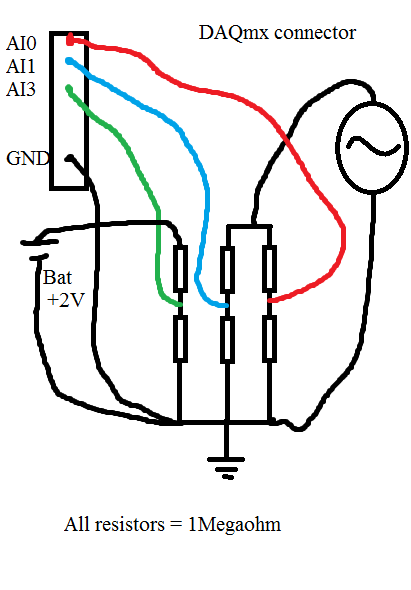
I had a serious problem regarding the use of DAQmx USB-6225. Please look at my diagram below:
When I measure the waveform sine on AI0, everything is OK. Even with a very sampling rate high as 80kS.
When I measure the waveform sine on AI1, everything is OK. Even with a very sampling rate high as 80kS.
When I measure the battery voltage on AI2 CC, everything is OK. Even with a very sampling rate high as 80kS.
Now comes the problem:
If I measure all three analog inputs or the two and two together, I get a very different result when I measured one and a single channel. If I add more channels (i.e AI3 and AI4) on my USB-6225 DAQmx, without connect anything to them, I can see the sinuses even as I do with AI0 AI1, but with less amplitude.
When I measure the voltage as well as AI0 and/or AI1, the domain controller becomes sinus armor as well. If I connect the + 2 V DC directly to data acquisition without resistance, I see a line perfectly DC on my chart, but with the sinus AI3 and AI4 top.
If I use an oscilloscope and measured directly on the same wire that goes to my data acquisition and the resistorcoupling, I can see small pulses of the samplingfrequency and the signal seems quite noisy.
That's my big problem:
Everything works perfectly if I use R<100Kohm. any="" value="" below="" 100k="" is="" ok.="" this="" coupling="" on="" the="" schematic="" is="" just="" a="" test.="" the="" trouble="" comes="" when="" i="" need="" to="" measure="" a="" circuitboard="" that="" draws="" energy="" from="" a="" capacitors="" in="" the="" circuit.="" if="" i="" use="" any="" resistors="" below="" 1megaohm,="" it="" draws="" energy="" from="" the="" circuitboard="" and="" the="" test="" is="" not="">
Anyone with some experience around this problem? The impedance of the analog input on my USB-6225 DAQmx is 10Gigaohm so it should not really been an issue.
Here is what I tried:
With the help of a D - sub cable with shield. I tried to use with no shield shield closed, I have both ends and closed, the shield only on my DAQ.
I checked my code and also just used the DAQ assistant.
I checked all parts off my setup for groundcircuits and I twisted each cable from any power supply, the signalgenerators, the DAQ cables.
I have connected my DAQ to mainsground (in the wallcontact 230V and Yes, we use 230V in Norway). Also any other equipment.
I connected without mainsground. Also any other equipment.
I tried cables as short as possible.
I tried to use the differential, CSR (Respect to GND), NRSE (Respect to the sense of IT). Nothing has worked.
I tried to use as sample rate and samples possible. (It helped a little when the DC measurement and AN analog input. If I tried all three, he has yet again).
All this comes to mind that the USB-6225 DAQmx cannot manage measuring more than resistors with values around 1Megaohm and above.
The answers will be rewarded with congratulations and a sincierly 'Thank You '.
Hi guys again!
Bother replying this thread

I'm a guy. I don't read manuals! But now that I did... And. There are 4 pages describing my problem and what to do about it. So problem solved
I have experience ghostvoltage of the other channels due to the high - impedance of the source. I created a follower of tension with an op-amp and the problem disappeared! Thank you ni.com/info/f/. Do you have answers for everthing is there to inquire. Except why I ran out of beer. mmm beer!
-
How can I pause and resume the analog output using DAQmx?
I use a DAQ hardware to produce an analog waveform. I would like simply to break the output of the wave and then resume where it left off. I use DAQmx and LabVIEW 2011.
I've seen examples that use a digital or analog break trigger, but I would take a break in the software only. How can I do this?
-Joe
Hi Joe!
I spent some time thinking about it and I realized that you can technically use a fundamental mission of the analog output, as you previously wrote that runs continuously. However, the generated output samples are controlled by the sample clock pulses, and can be manipulated to fit our needs "suspension."
To do this, we will need another counter task that generates a pulse train (see our examples of shipping under material input and output > DAQmx > generating digital pulses > generate dig Pulse Train - Continuous.vi) that stops and starts the user to choose. This can be in another quite VI or controlled by software. We will use this as the task of our output sample clock.
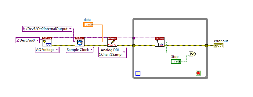
Then, the task of the AO, wire a constant to the sample clock source and select ' DevX/CtrXInternalOutput"based on the counter that you specified in the task of counter. You will need to choose "I/o name of filtration" and check the box that says "include advanced terminals' and right-click of the constant. See picture attached as a reference. In this way, the task of the AO is constantly running, but it generates only actually all data when the meter running task.
Let me know if you have any questions!
Have a great day!
-
Input analog continuous USB DAQ find amplitude peak to peak
I need to know if there is a way to use the crest detector when you do an analog voltage input. I use c# VS2005 and 8.6.
Hi jsheridan,
Have you looked at the Ridge detector example that comes with Measurement Studio? The c# example can be found here: C:\Documents and Settings\All Users\Documents\National Instruments\MStudioVS2005\DotNET\Examples\Analysis\PeakDetector\cs (assuming that you have installed on your C drive :).
The example generates a waveform and uses the PeakDetector class to detect the peaks. You can take this example and modify it to support what you are doing, or just put some functions in your code. The detector function takes an array and outputs tables of places, the amplitudes and the second derivatives of the peaks and valleys in the array passed to it. If you prefer to use all the time, you could just do a ridge detection after each reading some or all few seconds so that you make a lot of unnecessary calculations.
-
How to distinguish the samples from 6 different inputs analog
Hello everyone, I'm still new to NOR-DAQmx. I write a C++ program that reads 6 analog inputs of the card PCI-6220.
Basically, I created 6 virtual channels in a single task, looks like I'm acquisition of required inputs.
However, the problem is that I don't know which sample comes from what analog input channel. I put the fill mode "DAQmx_Val_GroupByChannel".
Please help me, how can I distinguish between samples of different analog inputs.
Best regards from Kazakhstan,
Khassan
Khassan,
Channel order would be decided in the order in which you added your channels to the task. So let's say I create a task and adds three channels and add them in the order ai0 ai1 and ai2. If I set the fill to "DAQmx_Val_GroupByChannel" mode, DAQmxRead will copy data in "readArray' such that ai0 data all together, followed by the data of ai1, which is followed by the data of ai2. The size of each of these sections of the buffer must be returned through the 'sampsPerChanRead' argument to read. So if were to call read and DAQmx returned 5 for "sampsPerChanRead", then my data buffer would look like this:
AI0, ai0, ai0, ai0, ai0, ai1, ai1, ai1, ai1, ai1, ai2, ai2, ai2, ai2, ai2
Hope that helps,
Dan
-
Recently, I was unable to read an analog signal. I use a TBX-68 block attached to a card PCI-MIO-16XE-50. The signal will be max to everything I put the maximum voltage reading when I hang anything to her. It will read zero volts with noise when the wires are not connected to anything and it will read somewhere around 6 + / 2 volts when two wires are connected to each other, far away from the 0 volt I expect. I tried to replace the Board with another PCI-MIO-16XE-50 without success. I connected the wires to the different analog inputs too. I know that its reading of the entries that I hung up because it will react to what I do only for the entries that I've specified (is it is connected to AI 1 and I connect a battery to 2, playback is not affected). Digital and analog outputs are working properly.
Recently I am gone in DAQ Express changed some things for me to specify my front channels, but it does not work when I create a new too. Could I have definitely changed the DAQ Express? He was working before I messed up with this stuff, but it can also work after. I don't me remember the last time it worked however when I opened first the front of an Express DAQ.
I have attached a VI just that I expect to read the voltage input (even with nothing plugged, it's the reading-10 volts).
Hey, pagoda.
Looks like you may be in differential configuration and cannot be biasing the input rows. Differential configuration, the two lines of entry of a channel must receive ground somehow bias; It may be through enormous resistance, but something to attach the tension to keep them from floating away. Connect the + and - lines together is not enough, because that does not provide a path to Earth.
Try to connect both + and - directly to the analog ground and see if you read a quiet 0 V. If it works, then connect the inputs to everything you want to measure. As long as both + and - has a way of DC grounded, however diverted, everything should work fine.
Normally, if your source is floating, you'll want to link the - entry to your device and the mass also directly to analog. If your source is connected, you should not connect - ground, since it is probably already connected.
Hope this helps,
EBL
-
Hi all
I use USB - 6363 CVI 2013 with patches and trying to solve this problem for days. But just does not know what the problem is.
Basically I have a finite periods display analog sine wave (which works fine), then I would like to receive (or other stuff) to an analog pathway for the objective test.
The thing is that I can't get anything this either port HAVE, straight zeros in this table. I tried to put some DAQmxCfgAnlgEdgeStartTrig on the port of AI0 but still no result. and right now
I don't have the ability to test if APFI0 method will work or not. So now I'm on an internal trigger.
Here's what I did to get so far, no error. But all I see on the result of the sinearrayfin table is zeros. sinearrayf matches the entry and tested to have the data in it.
sinearrayf = (float64 *) malloc (800 * arraysize4 * sizeof (float64));
for (int f = 0; f)<>
{
sinearrayf [f] = sinearray (float64) [f];
}
sinearrayfin = (float64 *) malloc (800 * arraysize4 * sizeof (float64));
for (int f = 0; f)<>
{
sinearrayfin [f] = 0;
}error int = 0;
char errBuff [2048] = {'\0'};
trigName char [256];
Written Int32 = 0;DAQmxErrChk (DAQmxCreateTask("",&AItaskHandle));
DAQmxErrChk (DAQmxCreateAIVoltageChan(AItaskHandle,"/Dev1/ai0","",DAQmx_Val_Cfg_Default,-10.0,10.0,DAQmx_Val_Volts,NULL));
DAQmxErrChk (DAQmxCfgSampClkTiming(AItaskHandle,"",800000.0,DAQmx_Val_Rising,DAQmx_Val_ContSamps,800*arraysize4));
DAQmxErrChk (GetTerminalNameWithDevPrefix(AItaskHandle,"ai/StartTrigger",trigName));DAQmxErrChk (DAQmxCreateTask("",&AOtaskHandle));
DAQmxErrChk (DAQmxCreateAOVoltageChan(AOtaskHandle,"Dev1/ao0","",-10.0,10.0,DAQmx_Val_Volts,NULL));
DAQmxErrChk (DAQmxCfgSampClkTiming(AOtaskHandle,"",800000.0,DAQmx_Val_Rising,DAQmx_Val_FiniteSamps,800*arraysize4));
DAQmxErrChk (DAQmxCfgDigEdgeStartTrig (AOtaskHandle, trigName, DAQmx_Val_Rising));DAQmxErrChk (DAQmxWriteAnalogF64 (AOtaskHandle, 800 * arraysize4, 0, 10.0, DAQmx_Val_GroupByChannel,sinearrayf, & writing, NULL));
DAQmxErrChk (DAQmxRegisterDoneEvent(AOtaskHandle,0,DoneCallback,));DAQmxErrChk (DAQmxRegisterEveryNSamplesEvent (AItaskHandle, DAQmx_Val_Acquired_Into_Buffer, 10000, 0, EveryNCallback, NULL));
    /*********************************************/

    Starting code DAQmx
/*********************************************/DAQmxErrChk (DAQmxStartTask (AOtaskHandle));
DAQmxErrChk (DAQmxStartTask (AItaskHandle));
Error:
If (DAQmxFailed (error))
DAQmxGetExtendedErrorInfo (errBuff, 2048);
If (AItaskHandle! = 0) {}
/*********************************************/
Stop DAQmx code
/*********************************************/
DAQmxStopTask (AItaskHandle);
DAQmxClearTask (AItaskHandle);
}
If (AOtaskHandle! = 0) {}
/*********************************************/
Stop DAQmx code
/*********************************************/
DAQmxStopTask (AOtaskHandle);
DAQmxClearTask (AOtaskHandle);
}
If (DAQmxFailed (error))
printf ("error DAQmx: %s\n",errBuff); ").......
Int32 CVICALLBACK EveryNCallback(TaskHandle taskHandle, int32 everyNsamplesEventType, uInt32 nSamples, void *callbackData)
{
Int32 error = 0;
char errBuff [2048] = {'\0'};
public static int totalAI = 0;
readAI of Int32;DAQmxErrChk (DAQmxReadAnalogF64 (AItaskHandle,-1, 10.0, DAQmx_Val_GroupByChannel,sinearrayfin, 800 * arraysize4 & readAI, NULL));
fflush (stdout);
return 0;
}What I see from a quick look at the code that you understood, looks that you stop tasks without giving a sample of 10,000 time to accumulate in the buffer. This section of code here: does the following:
/*********************************************/
Starting code DAQmx
/*********************************************/
DAQmxErrChk (DAQmxStartTask (AOtaskHandle)); Start the task of AO
DAQmxErrChk (DAQmxStartTask (AItaskHandle)); Start the task of HAVEThere is no waiting or anything here which would be
stop the section error to be executed immediately
Error:
If (DAQmxFailed (error)) / / there is no error if this section does not
DAQmxGetExtendedErrorInfo (errBuff, 2048);
If (AItaskHandle! = 0) {/ / there is a task of so HAVE this section not}
/*********************************************/
Stop DAQmx code
/*********************************************/
DAQmxStopTask (AItaskHandle); Task of is stopped and deleted
DAQmxClearTask (AItaskHandle);}
If (AOtaskHandle! = 0) {/ / there is a task AO so this section runs as well}
/*********************************************/
Stop DAQmx code
/*********************************************/
DAQmxStopTask (AOtaskHandle); Task of the AO is arrested and cleared
DAQmxClearTask (AOtaskHandle);} / / The two tasks are arrested and cleared samples before
are allowed to accumulate in the buffer and call
the callback to perform playback DAQmx.If you look at the example of ' ContAck - IntClk.c ", he has a GetChar(); function between startup tasks and the block of the error. This actually awaits as you press a button before stopping and compensation tasks.
-
Configuration input: Terminal for voltage DAQmx block IA
I'm trying to get the "input terminal configuration" entry in a DAQmx "HAVE voltage" block to be "differential". I don't know how or where looking for something like this, functions pallate. I tried the examples find... thing nothing helped.
It's just the LabVIEW base. Right-click on the device, and then select 'create a constant '.
Maybe you are looking for
-
set cache, file name, name of the url automatically
I use foxit reader open a pdf file, the last name of the url is xxxx.pdf, when I click on save or save I get some strings like fileneme for example, 529EDd01.pdf. the same as the name in the cache folder. So, I think, first of all the xxxx.pdf of pdf
-
S-video on Satellite Pro A100 problem
Hi, I recently bought a new satellite pro a100 with XP pre-installed-one of my main reasons to choose this as the price was the built-in s-video connector so I can get my screen up on my tv. However, I have not yet got it working and you'd be gratefu
-
Hello!
-
Cannot access the internet on a network Windows XP when Windows 7 goes to sleep
Original title: Windows 7 Windows XP network problem. I replaced a Windows XP computer on my node 4 (2 PC, printer 2) cable network with a Windows 7 computer. When the Windows 7 computer in mode 'sleep' the other (XP) computer cannot access the inte
-
I have loaded Microsoft Highway 2007 on a memory stick to use on my netbook if far is 'axe' in a file but I can't open it on my netbook which also uses Windows XP. Any ideas on how I can open the file please?