Integrate USB DAQ 6008 program Labview
I'm new to LabVIEW and am currently writing a vi to access the 6008. I'm using LabVIEW 2012. I installed the driver NOR-DAQmx 3.6, however, the sample code is code c - no vi. Also, I can't see examples of NOR-DAQmx in the finder of the example. I downloaded various examples, but each are missing Subvi which I believe should be installed with the driver. All advice is appreciated.
Harry,
1 DAQmx Base is only supported on Mac OS. You can find petitions on the exchange of idea ask for better support.
2 DAQmx and all its beautiful examples are not installed on the Mac. This means that the measurement and Automation Explorer (MAX) is not installed on the Mac and things such as the DAQ Assistant exist (although it is not a great loss).
3. when DAQmx Base is installed on Mac OS X with LV 2012 you should have the DAQmx Base screws accessible from the measures of e/s palette.
4 installation DAQmx Base includes a bunch of examples in this direction: Applications: National Instruments: LabVIEW 2012: examples: daqmxbase: However, the example Finder doesn't seem to know they are there, then you will need to manually search.
One good thing about DAQmx Base is that it is almost entirely written in LabVIEW, so you can see what he does.
Once you get past the obstacles, the USB-6008 case works well with DAQmx Base and the Mac.
Lynn
Tags: NI Hardware
Similar Questions
-
Continuous output signal using usb DAQ 6008 in matlab
Hi Takou,
You already post with the same subject. Is this the same thing, isn't?
If so, refer to the following link:
How to get out a sinus with usb 6008 on MATLAB
Best regards
-
How to make accurate measurements at high impedance using NI USB DAQ 6343 in Labview
Hello. I use a DAQ 6343 for measurement of analog voltage on a signal of high impedance. I am aware that low impedance is recommended, but it is what is on my Board. I tried to measure several times to an A/D channel only, increasing the number of samples, sample rate reduction, and I find significant variations in all of the measures.
I wonder what is the best way to stabilize the A/D before taking a step on the way to analog input?
Thanks in advance for your help.
Jodi
Hi jschwatz100,
Here is a good link on ghost image, which talks about solutions for playback of a signal from a high impedance source:
http://digital.NI.com/public.nsf/allkb/73CB0FB296814E2286256FFD00028DDF?OpenDocument
I would recommend a circuit follower of simple tension of construction as a buffer between your signal source and data acquisition. Here is a Wikipedia article about it:
http://en.Wikipedia.org/wiki/Buffer_amplifier
I also recommend to maintain a ratio of 10:1 for your sample rate: Buffer Size(N Samples in Continuous Mode) and lowering/raising them both the same way.
DylanC
-
Get incremental counter/sound to work along side with action with usb-6008 with labview tia sal22
Get incremental counter/sound to work along the coast with usb-6008 with labview tia sal22
Hi all
I can get this vi to work if they are distinct from the vi but I can't join them together
Example of my error:
If buffers are set to 0 the freq counter increment works, but no sound
If the buffers are set to 1 the audio works fine but is not increment the Freq counter
If the buffers are attached to more 1 clicks and pops are comingThat's what I'm doing:
(1) have the frequency of increment of my internal sound card to a certain level as .01hz a second until he gets to 20 000 hz(2) use my device usb-6008 daq, which is connected to the same machine to measure the voltage at the same time. (I am in a position very low voltages between 1-5volts)
(3) output to a worksheet text file which will show you:
time in seconds, frequency, voltage
0,400.01,21,400.02,2.5
2,400.03,1
I'm a bit confused about how connect the increment and the audio during the measurements with the usb-6008 housing on the same machine
at the same time and in the same VI.Anyone have any ideas? I'm using labview 8.5
TIA sal22Ha ha you have been deceived by a dynamic thread. Insert a convert from Dynamic Data Express VI (Palette to own: Signal handling screw Express) between the daq read and build the array function. Then it won't work. Now the value in the dynamic data is only converted to a numeric value
-
Get the device USB-5133 by program number
I build systems integrated with many USB devices USB.
All the regular USB DAQ device number can be detected programmatically.
My USB-5133 (digitizer high speed) is not detected by program, by a feature in Labview.
I need this tool to communicate with my systems without manually selecting device number before running my application.
Hi Harold,.
Thanks for posting your question. Please check the following knowledge base
Best regards
Faris
-
NI USB box problem when Labview ends abnormally
Hi all
recently, I had a problem with the NI USB box used in Labview.
I wrote a very simple program and it runs in Labview 2011. Basically, it reads data from a NI USB box and also send data back. According to my knowledge (I don't know if it's good or bad), when the Labview is arrested shortly how it is completed, the USB box should also stop working. But the thing is, when the Labview program ends abnormally, let's say I directly terminate from the windows task manager when it is running, all the ports of the box USB will hold their final statements until I restart Labview and write new values to them.
This could be very dangerous. For example, when I use the USB box to control the power of a power supply, the Labview program crashes (which happens often), the power supply box and USB power will continue to work until I restart the program again. I tried several different types of boxes NI USB on PC and the problem still occurred. So I was wondering if there is no mechanism that prevents such problems or if I can do something programmatically to avoid it.
I thank very you much for your help and your time.
Best regards
Sun
Sun,
Another area where you can have a misconception: LabVIEW is not control USB DAQ device. The LabVIEW program called the DAQ driver program (typically DAQmx or DAQmx Base) and pilots say the OS to send messages via the USB port of the DAQ hardware. So stop the program LV, intentionally or accidentally, does not say the data acquisition driver and the OS USB driver to put the DAQ hardware in a State course.
If you have a configuration where the LV program can be stopped before it can send orders "Safe state" DAQ hardware, you cannot ensure the DAQ hardware stops correctly.
There are a few screws that have been written in LV "watchdog", but even those who depend on the operation of LV execution engine.
You should carefully rethink the entire system, make security issue, one of the main objectives at the beginning. Most likely, you will find that you need to a separate device, hardware clock or PLC, if the software fails to stop him. You should also consider whether you need a real-time operating system to avoid some of the problems associated with the standard desktop operating systems.
Lynn
-
Find the difference of pressure between the two transducers using a NI DAQ 6008
Hello
First of all, I'm a relatively inexperienced LabVIEW Developer, so my apologies in advance if this message does not have something, or otherwise lacks clarity.
I try to develop a VI as follows the pressure difference between the 2 EME 3100 pressure sensors (4-20 my), related to two different pressure lines, using a NO-DAQ 6008. I would like for the acquisition of data to read the two transducers, then have him find VI the differential and write this differential in an Excel file.
The data sheet for these sensors may be found at: http://www.gemssensors.com/Products/Pressure/Pressure-Tranducers/Sputtered-thin-film/~/media/GemsNA/... It is a 3-wire system, with a voltage between 8 - 24V. I use an external power supply of generic brand to power sensors, which provides a maximum of 24V @ 4A.
I drifted my physical connection (for the two transducers) this thread http://forums.ni.com/t5/LabVIEW/I-am-having-trouble-Omega-PX4200-Pressure-Transducers-to-where-I/m-p... and am relatively certain of the accuracy of the information. For purposes of signal conditioning, I use a 500 Ohm resistor between the signal of each transducer and the Earth wire. On the side of software, I use the latest version of LabVIEW (2011) as well as MAX on a Windows 7 64-bit machine.
In an ideal world, the sampling rate would be as high as possible, but 4 samples per second would suffice for all purposes useful.
Given this goal, are there any sample of VI (especially for MAX, which I have not yet used) who would be similar/applicable to this project, specifically, regarding setting a sampling frequency, calibration of the transducers or affecting the pins/channels appropriate? All resources would be greatly appreciated.
Kind regards
MG Wilkinson
Measure the voltage between the two resistance (resistance by probe 4-20 MA) using the differential inputs of the x 600.
When you configure the task, you can read several entries at once, by entering in "Dev_ / AI0:1" in the physical channels and using the "several channels / {unique |}". multiple} samples"polymorphic instance.
600 x can read 1kS/sec.
Do maths/conversions on the table, and then simply subtract the two tables.
Could also take some samples (10-100) at 1 kHz and their average together, give you a smaller rate effective sampling but with less noise.
A loop of producer-consumer would be good architecture here, let the daqmx reading live in a loop and sends the data via a queue to a 2nd consumer that performs mathematical operations and write to a file.

-
USB6363 DAQmx (reading and writing) calendar seems slower than other similar USB DAQ devices
Hey people,
I have currently a service waiting number with OR the subject, but I thought I'd post up incase anyone has ever dealt with a similar question pertaining to USB DAQ hardware.
Try to understand why there is a difference of synchronization between the 6363 USB and some of the other less expensive USB devices like the 6525 or 6501.

It's a watered the actual code that my team has noticed this difference in the simplified version. The actual code is a reading analog daqmx (it's triggered hw, so we begin the task of analog playback, trigger, wait the time we acquire to and then run reading daqmx. who takes 6 ms to read a single 50 values of the buffer).
Thank you
-Pat
Hi Pat,
Try benchmarking of HAVE it read that way (with the wait timed by the software, it seems to me that the task is probably not yet made to the time you want to read - I guess that the question is relative between the event of the task performed and all the data is available in the DAQmx buffer, I don't have a series of X USB to see) :
Try benchmarking your writing clocked by the software in this way (there no reason to include the check/reserve/validation/start sequence in your writing of reference when the task can easily be launched during initialization of your program):
On my PCIe X Series as the two cases take< 1="">
Best regards
-
Writing USB DAQ: Reading the data, analyze, analyzed data - does not
I have Labview 2011 32 bits (without tools), on Windows 7.
Material: Enclosure OR USB - 6251 DAQ board. I use analog analog out.
I'm trying to collect data (reading), analyze (like part or derivative) to a new waveform (or a data table)., then convert them this new waveform. As in this example:
http://zone.NI.com/reference/en-XX/help/370466V-01/mxcncpts/hwtimedsimio/
However, I don't have hardware timing.
I tried a lot of things. Those who work temporarily, until the start to write task threw an error: http://i.imgur.com/as5ItdO.png
Another who work temporarily, but it has a 7 second delay: http://i.imgur.com/VLbyZbo.png
Ends up having this error: Warning 200015 occurred
When writing to the buffer during a regeneration, the actual data generated may have alternated between the old and new data. In other words, while the pilot was replacing the old model of the buffer with the new model, the device could have generated some new data, while a part of the old data and then a part of the new data again.
Reduce the sampling frequency, use a larger buffer or refer to the documentation on DAQmx write me for more information on other ways to avoid this warning.
Can someone tell me what I'm missing? It seems very simple.
Thank you.
Thank you for an update. Sorry I missed you use hardware USB DAQ and this is the reason why we see this error
http://digital.NI.com/public.nsf/allkb/EC1968728E660B288625780700570D06?OpenDocument
In general, when you receive errors like that they give you a pretty good idea on what is going on. Therefore, you can try to remove your task AO timming daqmx or try to set the size of the buffer.
This might help
http://digital.NI.com/public.nsf/allkb/E1E67695E76BA75B86256DB1004E9B07
-
DAQ set of Labview, acquisition of DLL
Hello
I wonder if it is possible to do the configuration of NI DAQ card of labview, but acquisition of data from DLL written in C++?
Michael
Just an additional option:
If your creation/configuration of the task must be programming in LabVIEW, you can use the "storage screw" under measure i/o > NOR-DAQmx > advanced > System Setup > store to save a task programmatically. Then c++, you could just load this task.
-
How to debug the program Labview that runs in the target of the RT of a Compact RIO
I use CRIO-9073 for the acquisition of data from sensors. Program Labview is written in RT target and target FPGA. It is posssible to make step wise execution for the program written in the target RT and FPGA target the way purpose us for the debugging of the program in general OS.
MJM,
The only way to use the debugging on a VI wrote to FPGA tools is to simulate running on the host computer. You can then deploy the compiled FPGA code on the target and run your VI RT in debug mode if you use the communication of the façade with the host PC.
-
USB DAQ error after update to 15.1 DAQ
Everything worked well (DAQ 9.5) on my windows XP SP3 machine, so I thought that it's a good idea to install the last DQA 15.1, NOW my USB DAQ has a Red Cross in NI MAX and does not

I tried to reinstall OR DAQ 15.1, restarted the PC, plug the NIDAQ inside and out, but the error remains.
Any ideas how to solve this problem?
Thanks for the info. I tried the above and uninstall and reinstall everything, but in the end, the only thing that solved the problem was to install a new copy of the operating system, windows XP in this case.
-
Hi all.
I work with an application that is count the pulses of an encoder hollow shaft renco to measure the distance traveled on a platform single axis powered by a ball screw and controlled by an engine step by step. The encoder is mounted at the opposite end of the motor directly to the ball screws.
That said encoder has 100 impulses per revolution and at the moment im using only 1 channel on its release to make the count. I use the channel of single window on a DAQ 6008 real counting down.
Here's my problem.
When I run the engine at a moderate speed and measure count pulses from a full trip on the axis I get 8200 impulses. If I reverse the engine now and bring it back at the same speed, the full trip will give the same 8200 impulses which is exactly what I want. However, if I run the motor at extremely slow speeds the same 8200 impulses correspond to only 3 quarters of the race on the same axis.
My hypothesis is that at top speed the DAQ 6008 lacks a large number of charges. I am correct in this assumption? I will soon have access to a DAQ 6211. This will provide a more reliable metering device?.
Thanks in advance guys. I'd appreciate comments.
It is just as likely (if not more) that you are picking up additional indictments at the slower speed - you can confirm enough easily by calculating how many pulses to be emitted during the movement of the platform to the desired distance.
The signal directly from a quadrature encoder can be quite noisy. The 6008 is only able to edge simple counting, so no noise on a front amount could lead on Board being counted more than once.
The 6211 supports a specific type of channel linear encoder, which configures the meter to use both signals A and B of the encoder. In this mode, the meter requires alternating the edges of A and B to continue incrementing, which means a noisy transition will always only picked up like an edge.
In case you do not have access to both A and B signals (or if the encoder is particularly noisy for some reason any and produced false edges in the middle of a period of high/low), the 6211 also supports filters PFI (link pdf Manual of use).
Best regards
-
I try to print to a port usb of a program back in windows 7 32 bit profitional
I try to print to a port usb of a program back in windows 7 32 bit profitional
Hey
Try the procedure described on the site provided
http://geekswithblogs.NET/dtotzke/articles/26204.aspxSee you soon!
-
Design practice nor 6008 USB DAQ
Hello
I have a few question, I'd like to introduce. I need some sort of indication on how to better perform a timed cycle of acquisition driven by WSF.
I'll send my VI (conceptual, not one currently working one) and ask for explanations.
The goalI need to acquire a battery voltage. Load current consumption is driven by a couple of transistor. I drive the hollow transistors two digital i/o for USB data acquisition.
Because I need to have a power for a given time cycle, I need to have some sort of time control on the output.
So I wrote a simple state machine whose States are updated when a timer reaches zero. Each State has its own queue time.
Moreover, I differentiate between acquisition and control operations using two all in cycles.
First question: is this a correct way to a timed WSF of construction?and now:
The problem (s):
I need to connect and establish a correlation between the input line for the internal of the fsm States. So I madesome digital indicator on the face before of the VI and created a local variable (I know that local variables are BAD, but I had no other idea everything) to pass values for some time to the other.
I also want to select State sequent of the FMS based on the input value, I get a channel. I can stil use a local variable?
Are the two related tasks?
Second question: are local variables, something that I can use for this task?
Last but not least: I need to filter on the values.
In this vi I perform a filtering operation and then I get the I use for control of local variables.will be this filtering desync the two cycles while? will I run out of control before running the filtering?
The same question is valid for the purposes of registration: the unfiltered data record, I guess is unnecessary. But based on this 'architecture' I know the country reports and the recorded signals are out of sync (as happens in many game data acquired with this vi).
Is this a problem of logging (perhaps given by different buffers for data acquisition and internal State or something similar) or the whole WSF will be out of sync, then all acquired data is more useful because it is out of sync?Any advice would be much appreciated.
Best regards
Luca.
Luca,
Question 1: This is a reasonable start but need some things to make it a good WSF. There is no waiting or delay in the loop so it will run as fast as possible. U.S.-6008 outputs digital software timed so that the DAQ Assistant can take a long time, but the amount of time is unknown and not necessarily consistent from iteration to iteration. Since the DAQ Assistant Analog Input in the other races of loop to<= 10="" iterations="" per="" second,="" a="" wait="" of="" 100="" ms="" in="" the="" fsm="" loop="" seems="" like="" a="" good="" starting="" point.="" waiting="" 3000="" ms="" is="" not="" a="" good="" idea="" because="" the="" loop="" becomes="" unresponsive="" to="" the="" stop="" button="" for="" long="">
Do you need to write on the lines on each iteration, even when the data has not changed? Add a write state that is called only when the data changes.
The DAQ Assistant has a Stop input and an output of Stopped. When you are ready to stop the loop, the stop signal must be wired to these inputs so that the DAQ Assistant can delete tasks. The output of the order can be connected to a Terminal to stop the loop.
Problem (s):
It seems that you want to link the two loops. Local variables are usually a bad way to do it. The best way is to use queues. A queue can send the current state of the file loop. (More comments later if that's really what you need). Another line can send data, or better, the commands, the loop of the file to the loop.
I think you want digital output values rather than the State. Especially if you add a State writing as I suggested above, the current state will not always represent the condition of the power of your test. To make this work with the additional state Boolean matrix must be moved from one iteration to another via a shift register.
It seems that you have at least two controls to be sent from the loop of the file to the loop. One is the stop command. The other went to the higher power level control. You should probably have a command to set off power level which can be used if the battery voltage becomes too low and before stopping. How your program is currently configured, the last level of power will continue as long as the power of the computer is on and the USB-6008 is always plugged. The cessation program does NOT reset the lines.
When you use anti-parallel to the queues, you must be careful on the definition of wait times and the timed out case management.
The benefits of the queues are that it is easy to ensure synchronization at the level you need, the data can be stored according to the needs, and there are good examples. It also avoids the possibilities of race conditions, often introduced by local variables. This program could be based on a variation of the design producer/consumer model.
Filter questions: any filter introduces a time delay. In your case when you filter 100 samples 10 times per second, it is likely that the filter will do well until the next data set has arrived. The delay of the filter is not affecting your synchronization. The above lines will solve problems. Since you are looking at time of cycle seconds and the minimum interval on the order of 100 ms, the exact chronology (to tens of milliseconds level) is probably not too important.
The real question about filtering boils down to this: does the control work better if the signal is filtered?
- - - - -
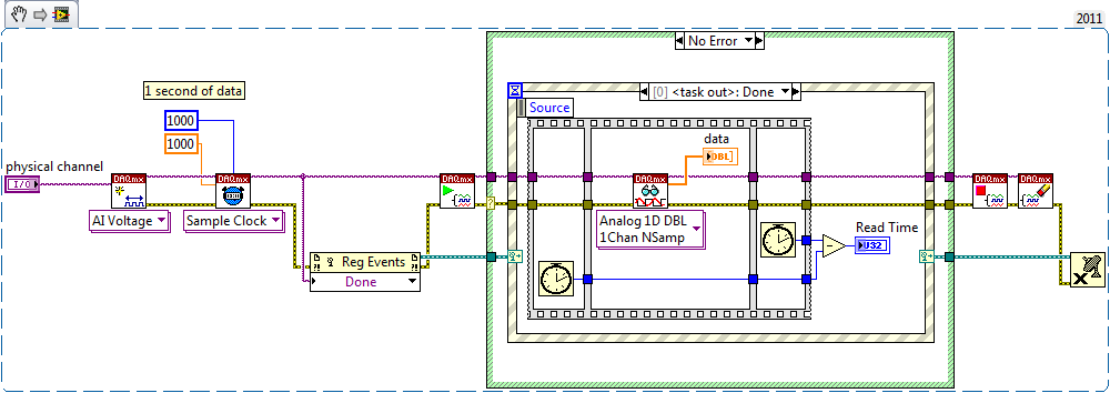
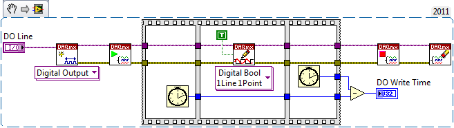
I'd probably all this a little differently. Given the slow speeds and the small amount of data, a simple loop with an improved state machine is all that is needed. Get rid of the DAQ Assistant and learn how to use DAQmx screws. States could include: Init THE Init, Init File, Idle, read, write, DO, Analyze, filter, adjust the power, wait, Save, close file, DO, AI Shutdown Shutdown, error and exit. No variables. No indicator fake just to allow the creation of local variables. Very little code outside the structure State case. None of the queues.
Lynn
Maybe you are looking for
-
Why is password required 3 times at startup?
Until a few days ago, when I open Thunderbird the morning everything worked fine. Now, every time I start Thunderbird earlier in the day that I am promoted a password. I enter the password and I am promoted to enter the new password, cancel or retry.
-
Re: Screen corruption after upgrading memory
I upgraded from 4 GB to 8 GB. He is recognized in the BIOS and begins to start. When windows loads the graphic screen, I get an increasing amount of horizontal lines until the machine stops. The BIOS version is 1.9
-
I want to programmatically create a list of appropriate channels to pass to a function such as DataBlDel(), which requires that the channels to be passed as a list of strings, which is a string. I don't want to build the string of concatinating a hac
-
GREAT SERVICE! need a picture of something
Hello Sorry to bother you I'm just about to hand in my thesis and I really need a picture of the VI, I created, but my laptop is not LabVIEW, I did it in the computers of the University. If you don't mind. I just need a picture of the full VI. Just t
-
Three days ago, I received an email from Windows stating that I needed to check my Hotmail account because Windows wanted to empty their list of users who have been idle, so I had 3 days to re sign up or I'd lose my Hotmail account. I was asked to fi