Continuous output signal using usb DAQ 6008 in matlab
Hi Takou,
You already post with the same subject. Is this the same thing, isn't?
If so, refer to the following link:
How to get out a sinus with usb 6008 on MATLAB
Best regards
Tags: NI Hardware
Similar Questions
-
USB-6009 slow output signals using SignalExpress - error 200077
We have a Council of USB-6009 and Signal Express version 3.5.0
We want to generate low-frequency, analog and digital outputs to simulate some slow movement process.
We have created the signals and their generated as output, put when we RUN the project, we get error 200077, which seems to indicate that we must use On Demand distribution of signals.
If we choose On Demand, then the generate DAQmx says we have a missing entry.
So, what method should be used with the slow USB-6009 to generate box (.01Hz and slower) analog and digital outputs?
These are 2 of the projects, we tried - using On Demand, N samples, continuous, internal, and external triggering etc..
Thanks adavance for your help...
Welcome to the forums of Steve,
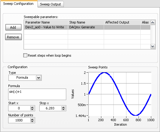
I have good news for you. I played a bit with the sweep and actually got a code facing up to generate a slow signal. I went and tested it with the 6009 and he was able to run without any errors. I joined here, but if you have to open (or anyone else in the future), here are some screenshots of how it works. If this works, feel free to make the forum as resolved while others can locate a solution a little easier in the future.
Scan Configuration:
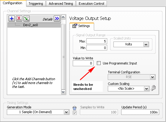
DAQmx Config:
-
Integrate USB DAQ 6008 program Labview
I'm new to LabVIEW and am currently writing a vi to access the 6008. I'm using LabVIEW 2012. I installed the driver NOR-DAQmx 3.6, however, the sample code is code c - no vi. Also, I can't see examples of NOR-DAQmx in the finder of the example. I downloaded various examples, but each are missing Subvi which I believe should be installed with the driver. All advice is appreciated.
Harry,
1 DAQmx Base is only supported on Mac OS. You can find petitions on the exchange of idea ask for better support.
2 DAQmx and all its beautiful examples are not installed on the Mac. This means that the measurement and Automation Explorer (MAX) is not installed on the Mac and things such as the DAQ Assistant exist (although it is not a great loss).
3. when DAQmx Base is installed on Mac OS X with LV 2012 you should have the DAQmx Base screws accessible from the measures of e/s palette.
4 installation DAQmx Base includes a bunch of examples in this direction: Applications: National Instruments: LabVIEW 2012: examples: daqmxbase: However, the example Finder doesn't seem to know they are there, then you will need to manually search.
One good thing about DAQmx Base is that it is almost entirely written in LabVIEW, so you can see what he does.
Once you get past the obstacles, the USB-6008 case works well with DAQmx Base and the Mac.
Lynn
-
Mutilates absorbent signals using MCC DAQ in Labview (error 10017)
Hi all
I'm working on a project that requires me to acquire several singals of a MCC DAQ and I tried a few differnet ways to do and can not understand. In the attached file, the upper part is the issue. The first waveform that I acquire works perfectly, but when I have duplicate and try to get another it shows a read error and displays a tip and a flat line then in the waveform table. I don't know if it's with the for loop or what. Any suggestion would be appreciated.
Thank you
Do NOT duplicate the it. Use a single task with many listed channels - Dev1\ai0:1.
-
can I use my DAQ on two different computers?
Hello.
Sorry if this may seem a stupid question, but I'm trying to save money lol. I have two test stations, each station has its own computer and power. Power supply powers a certain device and the computer communicate with him via a converter USB to RS422 series. I use the 2 analog outputs on my NI USB DAQ 6008/6009 controls 2 power supplies. AO 0 to check power supply to the station #1 and 1 A0 to control the electric power in the #2 station. I can control these 2 feeds very well with a computer connected to my DAQ. But I need every computer to run trials independently. I don't have that 1 DAQ but 2 computers, is there way to use this data acquisition on both computers?
Thanks for any help!
I found the easiest way for me to do this is to run two VI on a single computer. Since I have 3 usb ports on my labtop, I can use 2 of them to communicate through series with two of my devices and the 3rd for the acquisition of data.
Thanks Knight of NOR to make clear on the use of 2 computers.
-
USB 6008 digital output signal
I am VERY new to LabView and have been racking my brain trying to get digital output of my USB-6008. All I want is to be able to get a signal of + 5 V of my digital output when I click on a button. This signal opens a valve on a system I see so when it is pressed, it must stay open until I press the new button. It seems simple enough to me, but I'm not too familiar with LabView. Help, please!
Stripling07
You must first take the LabVIEW tutorials and then look at the links to get started with DAQmx .
The simplest program would be with the DAQ Assistant. Drop it on your schema, and then select digital output > digital line. Select the line when the wizard has completed, click OK. Wire a Boolean value in a table to build and the output of which is connected to the data entry. That's all. You can test the output of MAX (Measurement & Automation Explorer) with the test Panel. Do NOT test with your connected tap. Your valve may require more current that can provide the 6008.

-
Generate a continuous output of square wave with E Series DAQ cards
Hello
I use a card DAQ-AT-MIO-16XE-50 and labview 6.1 to generate the frequency divider. The first thing I want to do is to enter a continuous digital signal into the program so I can divide it. The attachment is the program I use. It's pretty simple, just read the output signal and put them all in a while loop to get a continuous pulse. But when I want to observe the waveform on the oscilloscope, I got some square waves unregular.
I'm a freshmen in labview. It will be appreciated for all her help!
Hello
If you are just getting started with digital i/o with traditional DAQ, I'd take a peek at some examples to see how to structure your code for both input and output. There is one here (http://zone.ni.com/devzone/cda/epd/p/id/1113) which should give some features similar to what you are looking for, but if you want more examples, you can navigate to the examples as a result of the article here (http://digital.ni.com/public.nsf/allkb/46D0C7360A10D25F862571B5007B4411), as long as you have installed them with traditional DAQ.
-
How to make accurate measurements at high impedance using NI USB DAQ 6343 in Labview
Hello. I use a DAQ 6343 for measurement of analog voltage on a signal of high impedance. I am aware that low impedance is recommended, but it is what is on my Board. I tried to measure several times to an A/D channel only, increasing the number of samples, sample rate reduction, and I find significant variations in all of the measures.
I wonder what is the best way to stabilize the A/D before taking a step on the way to analog input?
Thanks in advance for your help.
Jodi
Hi jschwatz100,
Here is a good link on ghost image, which talks about solutions for playback of a signal from a high impedance source:
http://digital.NI.com/public.nsf/allkb/73CB0FB296814E2286256FFD00028DDF?OpenDocument
I would recommend a circuit follower of simple tension of construction as a buffer between your signal source and data acquisition. Here is a Wikipedia article about it:
http://en.Wikipedia.org/wiki/Buffer_amplifier
I also recommend to maintain a ratio of 10:1 for your sample rate: Buffer Size(N Samples in Continuous Mode) and lowering/raising them both the same way.
DylanC
-
Can the USB-6210 output signal square 10 kHz?
I scoured the internet/forums to find out the maximum data rate for a USB-6210, but nothing helped. I know that the device can handle 250 kech. / s, but this does not appear to be linked to output speed.
By experimentation, I estimated the maximum rate 2500 kbps, but I fear that this figure may be inaccurate because I don't really know what I'm doing.
I would like to know:
(a) is the USB-6210 is able to produce a square wave of 10 kHz?(b) if not, is there a USB DAQ, which is?
Respectfully,.
Emrys Maier
University of Texas at Arlington Research Institute
Research Assistant
Let's see here. No analog outputs. Only software timed DIO, so it does not work. But there are 2 meters which should be able to output a square wave at the speed you need. I have not done it myself, but if you use the finder to the example and looking for something like 'pulse train' or 'exit meter', you should find some good examples of how to do it.
-
Find the difference of pressure between the two transducers using a NI DAQ 6008
Hello
First of all, I'm a relatively inexperienced LabVIEW Developer, so my apologies in advance if this message does not have something, or otherwise lacks clarity.
I try to develop a VI as follows the pressure difference between the 2 EME 3100 pressure sensors (4-20 my), related to two different pressure lines, using a NO-DAQ 6008. I would like for the acquisition of data to read the two transducers, then have him find VI the differential and write this differential in an Excel file.
The data sheet for these sensors may be found at: http://www.gemssensors.com/Products/Pressure/Pressure-Tranducers/Sputtered-thin-film/~/media/GemsNA/... It is a 3-wire system, with a voltage between 8 - 24V. I use an external power supply of generic brand to power sensors, which provides a maximum of 24V @ 4A.
I drifted my physical connection (for the two transducers) this thread http://forums.ni.com/t5/LabVIEW/I-am-having-trouble-Omega-PX4200-Pressure-Transducers-to-where-I/m-p... and am relatively certain of the accuracy of the information. For purposes of signal conditioning, I use a 500 Ohm resistor between the signal of each transducer and the Earth wire. On the side of software, I use the latest version of LabVIEW (2011) as well as MAX on a Windows 7 64-bit machine.
In an ideal world, the sampling rate would be as high as possible, but 4 samples per second would suffice for all purposes useful.
Given this goal, are there any sample of VI (especially for MAX, which I have not yet used) who would be similar/applicable to this project, specifically, regarding setting a sampling frequency, calibration of the transducers or affecting the pins/channels appropriate? All resources would be greatly appreciated.
Kind regards
MG Wilkinson
Measure the voltage between the two resistance (resistance by probe 4-20 MA) using the differential inputs of the x 600.
When you configure the task, you can read several entries at once, by entering in "Dev_ / AI0:1" in the physical channels and using the "several channels / {unique |}". multiple} samples"polymorphic instance.
600 x can read 1kS/sec.
Do maths/conversions on the table, and then simply subtract the two tables.
Could also take some samples (10-100) at 1 kHz and their average together, give you a smaller rate effective sampling but with less noise.
A loop of producer-consumer would be good architecture here, let the daqmx reading live in a loop and sends the data via a queue to a 2nd consumer that performs mathematical operations and write to a file.

-
Hello guys,.
I have a general question regarding the units of packaging such as the USB-9263 analog output signal. If I can use it instead of data acquisition to provide an analog voltage output?
Thank you
ELA
Yes, the 9263 can provide 4 output channels analog voltage (+/-10 v range) with up to 1mA of current drive. Looks like: it refers to the short circuit of conditioning of signals and some protection against overvoltage. Link below is the User Guide:
http://www.NI.com/PDF/manuals/372406b.PDF
-AK2DM
-
Using the DAQ USB-6009 meter and an analog input voltage at the same time.
Hello
Currently, I'm reading the two channels of voltage with the USB-6009. It happens that one of the channels is the output of a digital coder, and it would be much easier to use it directly to the PFIO entry that is defined as a counter. The problem I am facing right now, it's that I can't use the DAQ Assistant to use the analog voltage to a channel and the digital channel counter at the same time. Once I put the DAQ Assistant to read the input from analogue voltage, I won't be able to add analog inputs. And as I put the DAQ Assistant to use the PFIO as a counter, I can add more entries to read analog voltage is.
I wonder if it is possible to solve this problem using the lower level data blocks? Another solution would be to read two channels in analog input voltage and that the use of Matlab to process data resulting from it, since I was not able to do the counting to work simultaneously with the acquisition in Labview to impulses.
Hope you guys can help out me.
Thanks in advance.
Using a simple wizard of DAQ is incorrect. You need one to acquire analog inputs and one for the meter.
-
I want to vary the speed of a 12v dc fan using a mosfet with a DAQ 6008.Is this possible.
I am a college project that is to use a data acquisition to monitor and control the temperature. I use a LM35 temperature sensor. I need to control the speed of the fan a12v dc. I use an external power supply of dc 12. I hope to control the fan speed by varying the voltage of 5v to the door of the
MOSFET. Is this possible.
Hi shaggydog.
You can use one of the channels of analog output of the USB-6008 output a variable voltage to the gate MOSFET, this should provide the features you need.
-
How do I turn on/off outputs multiples with a single button using USB-6501 & Labview 2010
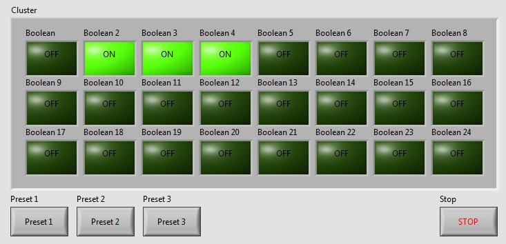
I've written a VI with 24 buttons, one for each output of the USB-6501, for turning on and off 24 relay. Now, I want to add more buttons that activate and deactivate the outputs multiple. We will call these Presets buttons and pressing the Preset button a few outings turn and some turn off. Get it? The VI I've included a screen shot is used to test a transmission controller and rather than to manually select one at a time relay I want a preset button that sets up instantly relays for the next stage of the event.
The VI I wrote uses tasks created in NI MAX.
I am a beginner of Labview, so please try to keep your easy to understand solutions if possible.
Thank you
Kevin
BTW, I'm registered in Core 1 and 2 month next to Richardson, Texas.
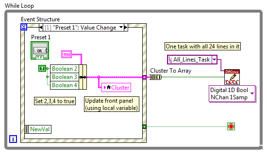
Here's an example - you will learn about the grapes, berries, events, etc., in the class, but this will give you a head start. Code is attached but I took a screenshot to give people an idea of how simple the schema becomes:
As your learn about them, I suggest you also make the cluster a TypeDef and make management mistakes, but I've omitted the example to keep things as simple as I could.
Good luck, LabVIEW learning, it is worth!
~ Simon
-
USB-6501 384 bit synchronized digital output signals
I need three digital signals (please see the attached file) to control a device, a signal is the clock signal, one is a continuous data signal 384 bit and another strobe signal that informs the device start and stop data. I have a USB-6501, this task can be achieved? I don't know how to write a 384-bit with DAQmx write signal, because it seems to support up to 32 bits. And it will be difficult to synchronize?
Thank you!
Hello the Stork
If you send 384 bits sequentially in a digital line; and running a timed software application, this would be possible (NI USB-6501 is a programmed software). See the example VI included below. In addition, please note that avoiding the nondeterministic East and will depend on the speed of your system. If you want to continue your application with one of our DIO cards that provide hardware timing capabilities; Please see the link below for more information about these devices.
Best regards
M Ali
Technical sales engineer
National Instruments
Maybe you are looking for
-
Why do I get an error page when I click on Options in tools?
I get a message that says that there is a problem loading the page.The address is not valid The URL is not valid and cannot be loaded. Web addresses are usually written like http://www.example.com/ Make sure that you're using forward slashes (i.e. /)
-
Why order new tab not working? Or by clicking on + sign on the tabs toolbar?
I looked at the response to the + sign does not. But could not understand what exactly was the solution. The file > new tab command is the same as clicking the sign +. Does not work for me UNLESS I have launch Firefox in "safe" mode (Option-click). I
-
Satellite C50 - B - 11 d - keyboard and NHY keys do not work
Hi N H key and there do not work on the keyboard, sometimes also the arrow keys does not work.any advise? or search and return? It s not even ages of two months and has this problem since day 1.Not only still used little. Very disappointing quality..
-
Hello I bought the new Dell Vostro 2520 webcam does not work except when opened with Skype or facebook. Can someone give me the link to download the drivers for the web cam. Thanks in advance, Siddhartha.
-
Hallo,I noticed that when in an OE I uncheck the required box for a field...... do not reflect the changes on the ground of the VO...As in the definitions of the VO, the check box is cleared, the only way to make the non-mandatory field is manually c