Invalid coordinate system?
Hey,.
I made a very simple script in assistant tool of vision - when I run inside the tool, everything goes well - but when I put it in my VI, I get an error of 'system of coordinates not valid'.
First, what I try to do is have a pattern match to locate my object, then I want a coordinate system based on the value and use it for a reference for the rest of the script - but no matter what I try, "coordinate system defined" outputs "NaN" - even if the special criteria works perfectly.
any ideas?
Hi Henrik
I encountered this problem as well. This is a bug in LabVIEW 2013, it needs to be corrected in 2014 of LabVIEW.
In the meantime, we have created a patch that you can use to solve this problem.
If you replace the attached file that is already there in this folder:
and restart LabVIEW you issue should be resolved. Best regards Anders Rohde | CLD | Platinum sales engineer | National Instruments Denmark
Tags: NI Hardware
Similar Questions
-
Create the reference coordinate system
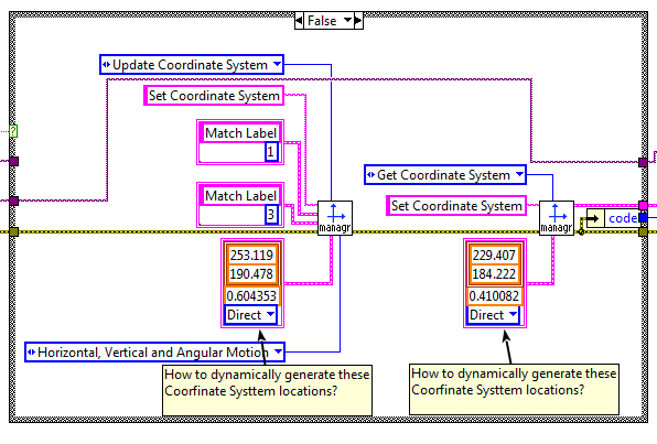
? Need help to dynamically create a reference guide. Use the Vision Assistant these constant reference of basic places are created automatically. I can't find any real documentation of the code examples on how to do it dynamically. See picture attached and the ZIP file for more details. Thanks in advance!
Label08.PNG must be perfect
Label10.PNG will show flaws
Locations of base generated by the Vision Assistant
Run the sample code Label_GoldenTemplate_L8.vi
This code illustrates the configuration and the use of the Golden dynamic reference coordinate system model inspection. Template_L8.PNG was created from Label08.png.
Update of the coordinate system: Location of Template_L8.png suitable for any image of the label. It's dynamic to each new image.
Get the coordinate system: Location of the model when the patterns matched with Label08, png (reference). It is static for each image of the future label.
Code is a bit "messy" because it was generated using NI Vision.
-
"Invalid Operating System" error when you try to load McAfee
I try to load the McAfee virus scan, but I get an error message "Invalid Operating System".
OS is XP Pro comes with the system and the current version is 5.1 service pack 3. It would not have automatically updated from Microsoft if the OS was not legal
Hello
· This only happens when you install McAfee virus or with the entire application?
· How you try to install McAfee on the system from the internet explore or a disc?
· Were you able to install McAfee before on the system?
· What is the exact error that you are experiencing when you try to install a program?
I suggest to install the application in clean boot mode and check if you are able to install the program or not.
How to configure Windows XP to start in a "clean boot" State
http://support.Microsoft.com/kb/310353
Thanks and regards.
Thahaseena M
Microsoft Answers Support Engineer.
Visit our Microsoft answers feedback Forum and let us know what you think. -
Is it possible to set the flash to the global coordinate system?
I try to finds the film of the symbols @ an exact position (relative to the root) and the X values and there are different depending on where is the highest symbol of film lvl. Which makes sense for everyone except me?
Thanks in advance for your help
Any symbol, you are creating essentially has its own system of corrdinate, and you can't things referenced to the coordinate system of the main timeline as any kind of built-in Flash editor.
-
Transformation of the coordinate system
I use company oracle 10.2.0.1
I'm trying to convert our ArcSDE that sit on top of RDBM oracle database, which is used to visualize on the map of the Earth to the oracle database. I have elevation data, latitude and longitude for a region (Rectangle shape) I want to insert into a column of type GEOM. I was going through the spatial reference guide, which has lots of information. My question is can I use this stmt to insert data of a shape of rectangle with the longitude/Latitude data?
INSERT INTO (VALUES) target_point
1,
"cola_a,"
MDSYS. SDO_GEOMETRY)
2003 - polygon 2 Dimensions
NULL,
NULL,
MDSYS. SDO_ELEM_INFO_ARRAY (1,1003,3), - a rectangle (1003 = outside)
MDSYS. SDO_ORDINATE_ARRAY (1, 1, 5, 7) - only 2 points needed to
-define the rectangle (bottom left and top right) with
-Cartesian-coordinate data
)
);
I also want to know what is the difference between that and the following stmt, that store all vertices?
INSERT INTO (VALUES) cola_markets_cs
1,
"cola_a,"
SDO_GEOMETRY)
2003 - two-dimensional polygon
8307,-SRID for ' Longitude / Latitude (WGS84) "coordinate system".
NULL,
SDO_ELEM_INFO_ARRAY (1,1003,1), - polygon
SDO_ORDINATE_ARRAY (1.1-5.1, 5.7, 1.7, 1.1) - all vertices must
-be defined for rectangle with geodetic data.
)
);
I'm new to spatial database and try to learn. Appreciate any help.
Thank youSince you have rectangles, you have two options.
Create a rectangle of 5 points (you will need to repeat the last coordinate to close the polygon).
Also affect the SRID 8307 since the values long/lat.SDO_GEOMETRY (2003, 8307, NULL,)
MDSYS. SDO_ELEM_INFO_ARRAY (1,1003,1),
MDSYS. SDO_ORDINATE_ARRAY (long1 lat1, long2, lat2, long3, lat3, long4, lat4, long1, lat1))And you can then use SDO_GEOM.sdo_centroid to calculate the centre of gravity in the application.
Regarding the altitude, is there an elevation for each coordinate value?
10.2, we do a lot with the values of height, but you can store around the geometry.Then eventually you create geometry 3D like this:
SDO_GEOMETRY (3003, 8307, NULL,
MDSYS. SDO_ELEM_INFO_ARRAY (1,1003,1),
MDSYS. SDO_ORDINATE_ARRAY (long1 lat1, alt1, long2, lat2, alt2, long3, lat3, alt3 long4, lat4, alt4, alt1, lat1, long1))But in this way, everything becomes a little more complicated. So if you just want to make altitude autour, you better
account in a separate as well as the geometry column column.Siva
-
I bought a computer hp laptop with an invalid operating system
This laptop came factory with windows vista, but before I take possession of it, the previous owner had installed a windows 7 home prem upgrade disc. ! of course, it doesn't have a product key. It took a while before the message appeared to me.
is windows vista installation files still on this computer? What should I do? I can't afford to 140.00 for a product key. and my computer is already crazy. someone help me please. I love my H PSome computers that come pre-installed with Windows often have what is called a recovery partition. This is used to reinstall an operating system in the case of a system failure. To access it, you need to start when you start your computer by pressing a function key. This can be either F1, F2, F9, F10, F11, F12 key DEL or tab. See the manual that came with your PC for instructions on how to reinstall Windows.
This is how the recovery partition is accessible to most popular brands...
For HP, press F11 directly after switching on the device
If the recovery partition is damaged, see the following instructions to reinstall Vista:
-
How can I get the coordinates in the coordinate system of the layer by the iterate?
I found the function iterate position(x,y) tell me isn't fair sometimes.
In fact, it happens when the upper part of the layer is negative. The 'y' is in the system(maybe?) of coordination model but not the layer. In a Word, the position with y = 0 is not the top.
Specifically, I had the card of the color of a layer. I am able to get the color of each pixel in the layer. But I can not set the color for one when I use 'Browse', because there is a lag.
Am I supposed to get the offset? Is it possible to directly access the whole layer if I use an iteration function?
Therefore the offset in game indeed.
AE will decrease the buffer increments of 20% and not for every pixel that
going out of sight. It is not really related to the upper left corner,
It's all about what part of your layer buffer is not visible.
There is also a 'iterate the shift feature. Check it out. Perhaps it will be
save you a few difficulties.
Friday, December 19, 2014 at 2:45, Hinanawi Tenshi [email protected]>
-
Where to find the list of projected coordinate system support
Hello
Sombody can you please help me where to find the list of transformations of coordinates geodethic supported for space? TIA
TamasYes, you would sdo_cs.transform (column_name, 8307)
-
Lenovo G560 INVALID INVALID, Lenovo SN system model
Hello
I have lenevo model G560
When I check ystem information it shows invalid model system and also the SN system as being not valid
The LENOVO system manufacturer
INVALID system model
System Type X 86-based PC
Processor Intel (r) Core i3 CPU M 380 @ 2.53 GHz, 2533 Mhz, 2 Lossnay, 4 logical processors
BIOS Version/Date LENOVO 29CN38WW (V2.15), 28/01/2011
SMBIOS Version 2.6You will need to contact the Lenovo Support again and have them update the computer with this information.
-
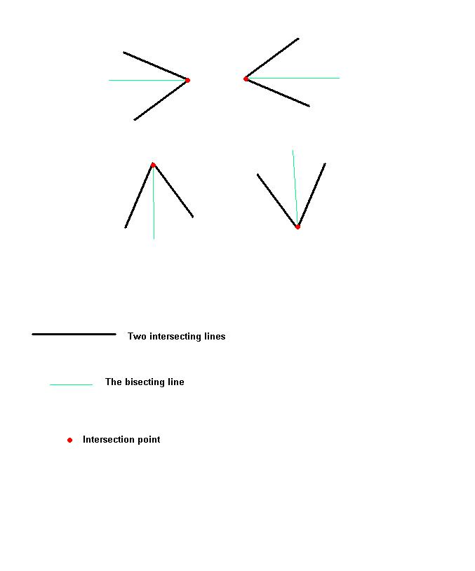
Angle between two independent lines of the universal coordinate reference system
I have 4 different routed as on the attachment. The points of the black lines are from edge detection. Two lines (black) intersect at a point (red). Green is the bisector. In all cases the angle between lines should be 45 degrees. .. At the present time in some cases, I get to + 45 degrees, + 135, -135, -45 degrees. Is there a way to get the angle between two lines independent of the coordinate system?
Or ideas?Try this:

-
VBAI: Problem of coordinate reference system
In a stage of my VB AI application, I'm set a mark at the center of a circular object correctly. In the next step, I do a 'find circular edge', including the "Reposition region of interest" value to a coordinate system.
However, when the object is moving, and the coordinate system with it, find a circular RIM does not follow this coordinate system, but rather remains fixed in space.
What should I do to have find a circular rim move with the coordinate system?
Make sure that when you set up the step of the coordinate system, you put up-to-date in the X direction and Y. By default it puts just updated in the X direction, and even if the overlay appears updated in both directions, this can be misleading. If this isn't the problem, you can include a simple inspection with some images to illustrate how you got in this State.
Thank you
Brad
-
Coordinate on reliable data system
Hello
I just started to enter during last nights pixel bender. Basically, I want to do the equivalent of subsampling and smoothing the image - but with audio data. Basically I want to get the sound sample data down to a manageable data set to draw a waveform.
So, with an image, I can get the values of the pixels of the 8 pixels around the 9th pixel Center.
I have not tried it on the sound sample data again, as I'm trying to see what I have to do. How the coordinate system is managed with an array of bytes instead of an image? Is this something like a strong image of a pixel, where width is the width of the byte array? Basically, I wonder if I need to worry about the axis y at all.
Thank you!
If you use a ShaderJob sends you the data as a 1 dimensional of the buffer, but this will gaurantee you some bad performances, because the player corinne upwards data to work on the use of lines.
Ideally you want to pass in a 2 dimensional buffer and the use of the width and the height of the buffer as a parameter to let you index for nearest left and right samples.
In the example of mixer that I posted on my blog, I used float4s as values in a 2D power buffer in the samples in the form Sample1Left, Sample1Right, Sample2Left, Sample2Right for even better performance.
I have a code of audio processing more sophisticated that I have written in Pixel Bender that I intend to go out when I had the chance that uses several samples. If I have time, I'll see if I can post here.
-
SYSTEM of COORDINATES TRANSFORMATION (I think)
Hi all
I need help here. I have a table (which started as a shape file) with a different coordinate system than I use. I can change the SRID and diminfo easy enough but the x / y coordinates are in a different system and I do not know how to convert them.
Help, please!
Here are the details:
-An example of the geometry column I'm shooting for registration:
-An example of record of the column of my table of problem geometry:MDSYS.SDO_GEOMETRY(2001, 8265, NULL, MDSYS.SDO_ELEM_INFO_ARRAY(1,1,1), MDSYS.SDO_ORDINATE_ARRAY(-79.249266,35.774167))
I already changed the SRID in the latter, but the real problem I have is in the MDSYS. SDO_ORDINATE_ARRAY. How can I convert my coordinates of problem (the example of the latter) to the same kind of information as the previous example for each record in the geometry column?MDSYS.SDO_GEOMETRY(2001, 8265, NULL, MDSYS.SDO_ELEM_INFO_ARRAY(1,1,1), MDSYS.SDO_ORDINATE_ARRAY(2012815.139204471,768438.258117677))
Thank you in advance!Indeed, for this, you'll need transform geometries of one system of CS (your form source) to another (existing table used).
It's little script that allows you to transform your 'table' or 'sex', based on the
SDO_CS. TRANSFORM_LAYER
[http://download.oracle.com/docs/html/B14255_01/sdo_cs_ref.htm#sthref1408]
Change in this script SOURCE_TABLE with your TABLE NAME
Change in this script TARGET_SRID with your TARGET SRID
Replace in the SOURCE_TABLE_SPATIAL_INDEX_NAME script with the name of the spatial index on your table in the source
--===============================================================================
-Run SDO_CS. TRANSFORM the layer
RUN SDO_CS. TRANSFORM_LAYER ('SOURCE_TABLE', 'GEOMETRY', 'SOURCE_TABLE_TRANSF', TARGET_SRID);
Quickly transformed layer;--===============================================================================
-DROP SOURCE TABEL SPATIAL INDEX
DROP INDEX SOURCE_TABLE_SPATIAL_INDEX_NAME;
COMMIT;
--===============================================================================
-execution of the procedure to update the source table
DECLARECURSOR c1_cur IS SELECT sdo_rowid, geometry OF SOURCE_TABLE_TRANSF;
l_tekst varchar2 (20);
c_rowprocessed CONSTANT number (3): = 500;
my_loops pls_integer;BEGIN
my_loops: = 0;
FOR c1_rec IN c1_cur LOOP
UPDATE of SOURCE_TABLE one
SET a.GEOMETRY = c1_rec. geometry
WHERE a.rowid = c1_rec.sdo_rowid;my_loops: = my_loops + 1;
If mod (number of lines c1_cur %, c_rowprocessed) = 0 thencommit;
end if;
end loop;
commit;
end;
/
Geometry of layer QUICK update;
--===============================================================================
-REMOVE the Source heading in USER_SDO_GEOM_METADATA REMOVE USER_SDO_GEOM_METADATA
WHERE
TABLE_NAME = 'SOURCE_TABLE.
AND
COLUMN_NAME = 'GEOMETRY ';
COMMIT;
--===============================================================================
-integration with the DETAILS DIM_ELEMENT and SRID USER_SDO_GEOM_METADATA
INSERT IN USER_SDO_GEOM_METADATA
VALUES
(
"SOURCE_TABLE."
"GEOMETRY."
MDSYS. SDO_DIM_ARRAY
(
MDSYS. SDO_DIM_ELEMENT ('X', 0, 300000, 0.00001),
MDSYS. SDO_DIM_ELEMENT ('Y', 0, 300000, 0.00001)
),
TARGET_SRID
);
COMMIT;
--===============================================================================
-Recreate the index
CREATING INDEXES
SOURCE_TABLE_SPATIAL_INDEX_NAME
WE
SOURCE_TABLE (GEOMETRY)
INDEXTYPE IS MDSYS. SPATIAL_INDEX;
Commit;
INVITES the 2 Spatial Index created;
--===============================================================================
-DROP the SOURCE_TABLE_TRANSF table
DROP TABLE SOURCE_TABLE_TRANSF;
COMMIT;Hoping that it would be.
Luke
-
Tiara retrieve coordinate of cursor using script
As a newcomer to this site, I say hello to everyone.
My question is simple:
How can I get the (X, Y) values shown on the curve of my report 2D graphics using the coordinates of the curve 'Add' (right-click on the curve) as input to a script, the values I use for further calculation in this script (essentially the difference between Xs)?
I join a picture of that.
In addition, I want to work with the report and not the view.
I hope you can help me

For us all.
Louval
Hi Louval,
the function that you use brand all the coordinates in your coordinate system, but not a special point on your chart.
In DIAdem script is no object that refers to this feature.
You can do for example:
See pics or other special point on you chart.
This could look like this:
Call ChnPeakFind("Example/Zeit","[1]/Drehzahl","[1]/PeakX","[1]/PeakY",4,"Max.Peaks","Amplitude") '... XW, Y, E, E, PeakNo, PeakType, PeakSort
So, what do you score? No matter how much of the system or the peculiarities of the curves as in the attached picture?Kind regards
Philipp K
AE | NIG.
-
Hello
I use the getting started with NI 951 x Modules in the series C and LabVIEW tutorial and I can't seem to make it work. I followed step by step and when I clicked on run on the front, I got the following error. Error code: 70028
Linear displacement during the definition of the position [] on the test Section.
The resource is not large enough to perform the specified operation.«"" "String of full appeal:»»"»
nimc.getLastErrorOnInterface.vi
nimc.fb.straightLineMove.startStraightLineMove.coordinate.modeAbsolute.0.vi:1
Straight line move 2. VII didn't create a 3-axis coordinate space and tutorial for two calls. I tried to remove one axis and by using only two, but that did not work. My diagram looks the same as that of the example except that I seem to have only a SINGLE coordinated in my system (notice down left the wire connected to the position [] has only one box coordinated instead of two as in the example). I tried to leave and the recreation of the coordinate axis and the VI with the same result. Am I missing something? It seems that my coordinate system appears in table 1 x 0 instead of a table 1 x 3 or something?
I tried to restart the cRIO and start a whole new project, essentially from step 1 excluding the installation of the software on the cRIO. Please let me know if you have any advice or have had the same problems. Thank you
Maybe you are looking for
-
Numbers. retrieve different data depending on today's date
I made a dashboard on numbers 4.0 on MacBook Pro using macOS 10.12. I need to display some data from the month, so I need to change every month (extraction of data from a different cell depending on the month). Should what formula/s I use? In the col
-
Why not apple reimburses my application to buy
Why the apple support won't reimburse my application to buy
-
S540 Windows Shutdown 10 & sleep
After the upgrade to Windows 10 my S540 will not be stopped or sleep properly. To try to stop, I get the Red led in the keyboard Thinkpad logo flashes constantly and can hear the internal fan of overtime. This does not stop little matter how long I l
-
How can I download my library on my iPad?
How can I download my library on my iPad?
-
HP 20 2303 has: installation of Windows 7 drivers for HP 20-2303 has
Hello all, I need to install Windows 7 32 bit on my HP 20-2303 has to control a laboratory apparatus that had this software controller that does not work on 64 bit systems. It's all good, except that I cannot now use some material elements, who are i