Is it possible to measure digital signals with devices of simulations?
The simulated device configuration is the following:
9174 chassis cDAQ (cDAQ1)
-9215 (cDAQ1Mod1) (analog in)
-9401 (cDAQ1Mod2) (digital i/o)
With a digital line (e.g., line 4), I create a single pulse
------^---------....
where the circumflex indicates the pulse short and simple.
Is it possible to use a digital line (for example, the line 0) in to measure it in the device simulated using a kind of direct/indirect routing? If so, how a set to the top of the digital input read task essentially read the output on line 4, internally?
Thank you.
N ° as the DAQmx help explains, you do not have this ability with a simulated device.
Tags: NI Hardware
Similar Questions
-
MCE only receive digital signals with Toshiba USB hybrid TV
Hi, I have a problem with the USB hybrid TV, I want to use with Windows Media Center, it works fine, but I can see only digital Tv, no cable Tv. If I use the software provided with TV usb I can see digital cable and cable, but with Windows Media Center only digital television.
Can someone help me please?
Thank you!
Luca
Hello Luca
Please don't be crazy about me, but you have to understand that maybe it's not possible to use the material in any desired combination. This product is designed for all the cell phones (not only for units with WMCE. Because of this manufacturer is it comes with own software.
As you can see, it also works with WMCE and also digital. In my opinion it's the big thing. By the Way: AFAIK WMCE supports analog and digital TV by use of the antenna). Try Please also check some support WMCE or even forum WMCE site.
-
Qosmio G30-158: is it possible to watch digital TV with Qosmio Player?
Living near Paris, I recently purchased a QOSMIO G30-158 PC, with tuner hybrid, and even if it is easy enough to watch digital tv programs with Windows Media Center, I don't understand why the Qosmio Player can only watch the analogue programmes, but also non-digital programs (my Qosmio Player references are v4.4.1 built 2006030822)? Thanks for helping me
Alain
Hello
Yes, you are on the right.
The Qosmio player may be able to receive only analog TV signals and its not able handle of digital television.
If you want to watch digital channels, you must use the MCE.A few days ago I found this info on the net, but he did not also for me.
Now I know and u too ;)
-
How to read digital signals with pre-and post-trigger on a card PCI-6251
I have 22-bit parallel position of data entering TTL lines to 16 kHz with a pulse of marker that says when the data is valid. I also have a fault line which gives an impulse when an error condition is met. I want to read in the 22 lines of position with 500 positions of pre-event and post-event 500 data when the fault line says. How do I pre and post-déclencher lines digital input on a card PCI-6251?
If this is not possible on this map, which maps PCI would be possible?
-
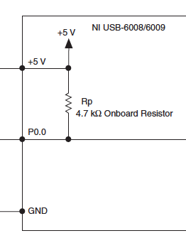
6008 USB shows the digital signal with nothing plugged
So I really hope that's not too bad, I guess it is.
I had problems reading of my digital USB 6008 entry this morning. Everything worked very well last night. Now all digital lines on the device to read a signal if it is has that anything connected to them or not. When I run the DAQ Assistant and test line, it shows a signal to each line. Then I did the joint VI (which should do the same) and it shows a constant signal in each line also. And I have nothing connected to the unit. Should reset somehow, or it is broken? Or am I just missing something?
nckeeley,
Look at pages 21 and 22 of the User Guide Ni USB-6008/6009 and specifications. Digital lines have a traction 4.7 kilohm place resistance to + 5 V. It will be a line of input opne look (and be) high.
Lynn
-
I would like to create a digital waveform as instructions for a stepper motor. The task is to get the motor shaft turn at variable speed within each rotation. I tried to do this by dividing the rotation in a number of blocks that each run at a different speed, thus forming the concatenated rotation profile.
The problem is that then the concatenation of the digital signals with the Append VI, I am unable to remember the different frequencies of the individual wave since the Append VI seem to require a constant interval between two pulses. Is it possible to explicitly concatenate accurate digital waveforms to form the desired profile?
Try again with the modified VI.
-
frequency of the digital signal 6009
Hello, how to generate the digital signal with frequency 50 Hz using NI USB-6009?
You can take a look at this:
Can I use a generation of impulses with the counters on the USB-6008/6009 case?
-
How can I get digital signals (interface UART) with a microcontroller with NI USB-6008?
I have acauired a few analog signals by A/D (3 channels). I put each scanned data on 3 digital output with a microcontroller. I want to see if it is possible to import these digital outputs 3 to a PC via a USB-6008? It's like the connection of the output to the digital input of the USB-6008 and import the 3 channels simultaneously to LabView? Do I need to use some other hardware like USB-8451 and connect the clock of the MCU to USB-8451?
Saraydin,
The digital I/o on the USB-6008 is a software program only, so unless your signals are rather slow, it probably will not work for you. In general, the procedure would be to connect each signal to one of the digital lines on the map and then set up a digital entry into LabVIEW task to read the three channels. If you use a device that has clocked by the digital i/o hardware, you then your input clock signal and use it as the sample for the task clock. Here is a list of USB devices supporting DIO clocked by the hardware. Also, there is an example that comes with LabVIEW, which shows how to do this. You can get to it in LabVIEW by going to help > find examples. When the example Finder window opens, navigate to hardware input and output > DAQmx > digital measures > Cont read dig Chan-Ext Clk.vi.
The 8451 is specifically for I2C and SPI, and would be great if you try to make one of these protocols, but otherwise I would recommend the devices in the list I linked above.
-Christina
-
Is it possible to transmit a signal between an entry and an exit signal with out nothing to do
Hi all
I use a DAQ 6601 map
I would take a simple digital signal input and go directly to an exit, until I get a different entry how I want to send my own signal to the output port.
I have a small program that reads a signal and then sends a signal to the good times the bit I'm stuck with sends just the entry of a terminal to the exit of another terminal and change something.
Thank you
Make a writing which was read just there because nothing more than this:
, you are going to have to explain what you're having a problem with.
-
is it possible to use my pdc3070 (camera digital polaroid) with vista? It seems to be ok with windows 7.
Hi James,
(1) what exactly happens when you try to use your camera?
(2) that you get an error message that you receive?
Please provide the exact model of your device number.
Method 1: Run the fixit available in the link below
Hardware devices do not work or are not detected in Windows
http://support.Microsoft.com/mats/hardware_device_problems/en-us
Method 2: Check for any error message in Device Manager
When a device is not functioning, Device Manager also typically displays an error message with an error code that comes with it. First, search for errors in the Manager of devices to do this, follow the steps below:
(a) open Device Manager by clicking the Start button, click on the Control Panel, clicking system and Maintenance, and then clicking Device Manager.
(b) If you are prompted for an administrator password or a confirmation, type the password or provide confirmation.
(c) in Device Manager, look for the camera and then double-click the device name.
(d) If an error code has been generated, the code appears in the status area of the device under the general tab
-
pulse width of measurement of signals generated by data acquisition
Finally, I would like to:
Start a counter pulse width measurement and the analog output at the same instant.
Stop the measurement with an external digital signal pulse width.My current plan is to use a digital output on the acquisition of data to synchronize a digital input and the start-up of the meter input. The digital input will be a trigger to start for the analog output. This works, except for the meter.
While trying to implement this, I tried a simple test to generate a digital pulse with the acquisition of data and wiring for counter inputs. It does not, even if it seems perfect to an oscilloscope. Then, without changing the software at all, I connect a function generator to my counter entries, and it measures pulse flawless widths.
I'm actually implemented it with a Python wrapper around the C DAQmx API, but I recreated in LabVIEW, and it has the same. VI attached. I have the latest drivers DAQmx.
Accidentally, I posted this in a forum for LabVIEW, as I managed to post with the account of a colleague. I think 2 ups live as this mandate to another post. I'm sorry. Former post is http://forums.ni.com/ni/board/message?board.id=170&message.id=389856.
Solution: I had to set the channel to counter with implicit synchronization. In addition, the sampsPerChanToAcquire must be at least 2, if not, there is an error. I still don't understand why it worked with a source of external impulse, however.
DAQmxCfgImplicitTiming (task_handle, DAQmx_Val_FiniteSamps, 2)
-
Acquire 2 digital signal of custom scale (Engg units)
I am a newbie to the world of DIO.
I write a VI to acquire 2 digital signals. one of a load cell and others for engine rpm (legumes). I need acquire these two signals and then convert them to engg units using the custom scale and write it in a txt file with timestamp.
Please suggest the best ways to accomplish this task.
Thank you
DAQG
Look at the examples on DAQmx in the finder of the example.
You would not really acquire 2 digital signals. You would acquire an analog signal of the load cell. A digital acquisition or against, this is what would make you the acquisition of the motor. Looking for analog and the counter measures in the finder of the example. Some of the example should show you how to apply the custom scale.
-
Synchronization of analog and digital output with the external sample clock
Hello
First of all sorry for my English, I will try to explain what I want to do.
I want my PCIe-6321 to send two custom signals (modification sawtooths) on a mirror controller. I would also like to generate output with my card at the beginning of each tooth of saw. Everything must be synchronized with an external k-clock signal of 100 kHz. The idea is that whenever the PCI receives a trigger to external clock, it sends two analog output voltages and when he received 1024 clock ticks it will also send a pic of triggering TTL. What I do is first prepare the map and after that in a loop sending and modifing the output values of the two signals and at the same time send a digital signal Boolean in each arch, so when's done it 1024 iterations of the loop I send an event to the digital port. Attached you can see.
The problem is that I don't know how to synchronize both. Can I use the sample clock just to the analog output? I can use sample for the two outputs clock, or do I need to use the output of the meter? If don't know how to use it here.
If I do nothing else bad/wrong, I would be grateful for feedback.
Thanks in advance,
PabloI don't know how but I find the solution. I'm generating more than a positive value (as I was triggered maybe very fast the oscilloscope has been absent there). If I put the sample clock of digital output to use the sampling/ao/Dev1 clock that it doesn't, but if I put to use the same source as the OD (terminal where my external clock is connected), but the trigger to start the DO to be Dev1/ao/StartTrigger this works. I don't really know why, but it does.
Thank you for your patience and your help. I put here the final code.
-
Measurement of frequency with CompactRio
Dear all
I have an anemometer which sends digital signals. I'm trying to analyze the signal to determine the speed of the wind.
I have one NOR cRio-9024 and NI 9205. When I connect the anemometer, it gives me some positives square rear tension (see attachment). I wonder if I could turn this to the readings of frequency because it is linear to the wind speed.
I tried to follow the link below, but my module does not have the option of digital Configuration specialist
http://digital.NI.com/public.nsf/allkb/C9088DFDF803CD8B862575F3007C40FD
or I should have another module OR who could measure the frequency of the signal directly?
I would like any ideas or suggestions. Thank you very much!
LabVIEW Newbie
-
Graph of digital signal using binary numbers.
I need to generate digital signals 4.
I have created a binary number which represents the 4 signals. (I don't know if I integrate it properly).Issues related to the:
1. How can I represents the binary number (4 signals) in a digital chart?
2 - is the right way to generate digital signals?
I need something like this:
Your code is meaningless.
- Why you build an array with one element is there is always only one item?
- Why are you doing floating point operations dealing with whren of integers?
- Your VI does not have a digital signal graph.
Try something like the joint to rotate the pieces...
Maybe you are looking for
-
Where to find 64-bit audio drivers for Satellite P100?
Anyone know where I can get the 64-bit drivers for my P100? The toshiba downloads section doesn't seem to provide 64-bit drivers either.
-
: I called the number, but I don't give any personal information. While the guy told me the code to download the system, I hung up. Should I be worried? All I have while on the phone was force quit safari, press SHIFT and safari and enter the website
-
We have a cottage on a lake north of access to water in Toronto. ........ No TV and no cell phone use... I have Dell laptop with Vista Just called Bell and told them what I can use to access the internet for my laptop and they suggested the Turbo key
-
Help me to library and apps cannot connect to the network
I followed all the steps Adobe me but all my Adobe apps still encounter the same problem. One of the solutions is to enter your port number in your browser, then I got the "upgrade required" message Pls help ASAP
-
Liscence from laptop to pc (microsoft)
Hi guys, I recently bought the liscence to use photography to Adobe... kit that was installed on my laptop...Today, I bought myself a PC and I am wondering how do I transfer my liscence mobile to PC.