Is someone spying on me?
Some strange things have developed to the end that suddenly somewhat concerned me that someone keeps track any activity on my macbook air.
I see nothing wrong in the file of applications, but I have to admit that I am somewhat a sucker when it comes to such things.
I checked the Applications system/preferences/Remote Login. It shows that it is on the off"" position.
I checked the Applications/Utilities/Terminal. It shows the following:
"Last login: Tuesday, 6 Oct 15:06:48 on console.
"Steves-MacBook-Air-2: ~ stephent * $".
There are, installed on my computer, an application called "Remote Desktop connection" which has the Windows flag as its icon, but it seems unusable because a ' windows computer is not found. "
What recommendations do you have for me to check that my keystrokes, e-mails, files generated, etc. are not followed in any event via remote access? Community, I thank you for your comments.
MacBook Air OS x 10.
The application "Remote Desktop connection" is a legitimate application which allows connect YOU to a remote PC. An older version of this app comes with all older versions of Microsoft Office. Therefore, unless you have other symptoms that someone spying on you, they probably aren't. Have the "Remote Desktop connection" application on your Mac is not an indication of espionage then you can be more comfortable.
Is something you should check out: 'System Preferences' > 'Security and privacy' > 'Firewall' > and make sure that your firewall is "ON".
Tags: Notebooks
Similar Questions
-
What are the twins in the bar address, friend being spyed on?
Sometimes, but not always, a small pair of binoculars will appear at the beginning of the address at the top of the display bar. This means that someone spying on me? I ran virus scan but nothing shows up!
You can attach a screenshot?
- http://en.Wikipedia.org/wiki/screenshot
- https://support.Mozilla.org/KB/how-do-i-create-screenshot-my-problem
Use a type of compressed as PNG or JPG image to save the screenshot.
Do you mean the purple icon that you see when you're in private browsing mode?
Make sure that you run not Firefox in private browsing mode (permanent) (don't forget the story never).
- Tools > Options > privacy > Firefox will be: "use the custom settings for history".
- Uncheck the box: [] "always use the navigation mode private.
-
DBRCrawler belongs to the directory Dell backup and recovery?
Today I noticed in my task manager, a process called DBRCrawler and when I open the file location was in C:\Program Files (x 86) \Dell backup and Recovery\Components\Shell.
Is this normal or should I someone spying on my computer?
Hi all
I'm the senior engineer Qualtiy for Dell backup and restore. DBRCrawler is a key component of Dell backup and restore. Its function is to ensure that the use of various application databases are synchronized between them.
It is the name of the file that triggered your concern?
Thank you very much
-
NEITHER USB-8452 - reach the maximum write SPI speed
Hello
I have a USB-8452 with the latest version of the software installed (2.1.2). The host computer is a Core i7. I am trying to achieve the maximum SPI write speed with the camera possible. I tried the basic block read/write SPI, SPI Scripting blocks and SPINNAKER streaming, but the first two have large delays between CS falling and the data being written (with so that delays in loop), and the last seems to be useful only for read operations.
Can someone tell me if there is a way of a) reduce the time of installation for basic SPI / SPI Scripting or b) writing different values in a single stream of SPI? Thanks in advance for any help on this issue, even if it's just confirmation that yes they is hard limits that cannot be overcome with the LabVIEW 8452 interface at this time.
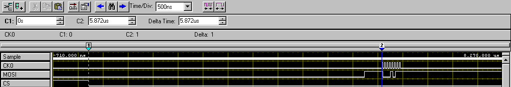
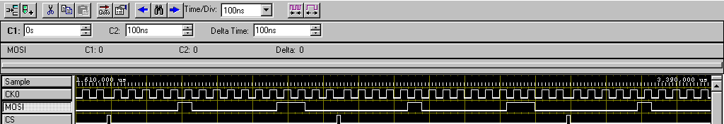
Here's the best I can do right now, as shown in my logic analyzer. Change of the SPI clock speed does not affect installation time and delays that are primary and secondary bottlenecks:
SPI read/write database-
Program: Basic Configuration followed by read/write of SPI block itself in a while loop
Main bottleneck: ~ 450 delay us into iterations of the loop (see Figure 2)
Secondary bottleneck: ~ 6 us delay between falling edge of CS and the first synchronization signal (see Figure 1)
Capture 1 - delay highlighting between CS falling and first SCLK pulse
2 delay highlighting between all iterations of the loop of capture
Scripts of SPI-
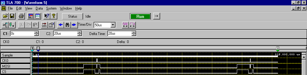
Program: Followed two Script blocks Basic Configuration run in a while loop (to check the two block to block and delay loop iteration)Main bottleneck: ~ 450 delay us into iterations of the loop (see Figure 3, space between the second and third images captured)
Secondary bottleneck: ~ 250 us delay between blocks of Script run consecutive (see Figure 3, space between the first and second captured images)
Capture 3 - highlighting delays consecutive run the Script and delays between while the loop iteration
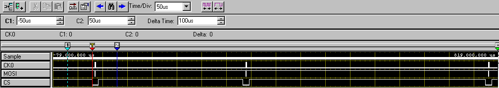
SPI in Streaming- It's the closest to achieve a fast writing speed, but unfortunately, it seems to be only useful for read operations (e.g., ADC), do not write.
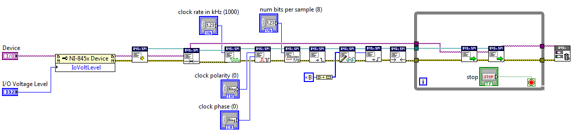
Program: Configuration of the base stream followed by start of the flow block
Main bottleneck: impossible to write something else than the data value unique property "wave 1-> MOSI data." I can write a byte array to this property, but it will simply put all these bytes in an image and repeat this framework (see Figure 4) rather than go through each value.
4 - two bytes sent repeatedly using SPI capture stream. Delay of CS is finally good, but no possibility to change the MOSI image to image data.
Hi JBender1,
This show looks like what we would expect for a 8452.
If you need higher performance, I encourage you to watch using a card R or FlexRIO FPGA series for your implementation.
-
Read only the SPI using the box USB-8451
I am using the NI USB-8451 box to read the SPI of a Honeywell digital pressure transducer data. The difficulty comes from that part of Honeywell uses only the SPI in half-duplex mode, meaning that it only transmits data, but does not require anything beyond the appropriate chip select signal and SCLK to start transmitting its 32-bit sensor data. To facilitate experimentation with the sensor, I bought a USB-8451 SPI Interface thinking I could easily configure the 8451 to read data from the sensor.
However, if I understand the situation, there is a problem. The 8451 considers full duplex data, i.e. a data word must first be sent to the SPI device in question before the unit will start to transmit back data of its own. And since the MOSI data writing periods, since this particular device starts transmitting immediately once a clock is applied, synchronizing the unused address data will cause the unit will return its data before the 8451 begins listening for data in return. The call used by the 8451 to write read action can be divided into the individual reading and actions of writing of any kind that I could discover.
Can someone tell me if I missed something in this operation or if there is some quick tips, that I could use to be able to use the 8451 therefor? Thank you!
Doug G.
Exactly correct. It's nice when things are easier than expected. Hope it works as easy as it sounds.
-
mcb2300 (lpc2378) SPI and external ADC
Hello
I use LabVIEW 2011 Embedded for ARM in collaboration with MCB2300 Development Council and MCP3204 12 - bit ADC chip. I try to use the base screws of SPI to communicate with the MCP3204. I enclose below the screenshot of my VI. Can someone tell me if this is a way of thinking? I would like to read the data from all 3 channels of ADC - 3 axes of the ADXL sensor connected. In addition, I have attached a few pages of the MCP3204 datasheet.
Thanks in advance
Hello
There is solution on NI Developer zone, which can help you - https://decibel.ni.com/content/docs/DOC-15231
-
Hello
I'm working on a project using the star LM3S8962 evaluation kit and a 4-channel analog digital converter 24-bit Texas Instruments ADS1274EVM.
I want to get the data sent by the ADC with the LM3S8962 using the SPI bus.
I have all of the example provided by the following link for my case: http://decibel.ni.com/content/docs/DOC-7701
The ADS1274EVM provides 2 pins for SPI communication: DOUT1 and SCLK.
When it becomes a clock on the SCLK pin, it starts to send data via DOUT1 pin, there is no pin slave select.
If I'm right, I don't have to connect:
-PIN SSICLK for the LM3S8962 with SCLK of the ADS1274EVM pin
-PIN SSIRX for the LM3S8962 with the pin of the ADS1274EVM DOUT1.
The ADS1274EVM is powered independently of the LM3S8962, so I connect VA WINE GND as shown on the http://decibel.ni.com/content/docs/DOC-7701page.
I write because it does not work: the ADS1274EVM sends no data given that I cannot get a clock signal of the SSICLK of the LM3S8962 pin that allows the ADS1274EVM start the conversion
I think that him 'ARM of SPI create Configuration reference VI' configures a clock that is sent through the LM3S8962 SSICLK pin, but it does not work as expected.
Can someone help me please? Thank you
Luke Y.
Hi Luke,.
I just tested the example and had no problem generating a clock on SSICLK.
I join the project I did with LV 2009 SP1. I hope that you could test and tell us if it works.
Kind regards
-
lines of NI8451 output level translator 3.3 to 5V on SPI
Hi all
If I use a NI8451 to talk to my DUT via SPI. I notice that the highest level of SPI tension disc is 3.3V. However, my NI DAQ SPI lines are each connected to a UPS (74HC14) on my HAD and my ups output is given me some odd readings. I think that the 3.3V signal generated by the 8451 is not always interpreted as a TTL high signal by the ups because it is falling between the thresholds high and low level. So, I want to implement a 3.3-> translator level 5V on my SCLK, MOSI, and CS lines so that the TTL levels are not be misread by the inverter.
I tried to use a SN7407 (open collector driver) with resistance to pull-up 10 k out 5V on all 3 of my SPI lines. I don't know if this is the correct way to do because the signals on my scope are not fair (SCLK don't work) and do not know if NI8451 e/s lines can support. I have attached a diagram of my connections. If someone could help me please on how to do this, I would be very happy!
Thanks again.
Serge
So missed me the resistance of the output of my data acquisition at the entrance of my level shifter. I guess I need this voltage drop on the SPI lines so that they would not be potentially exposed to receive a kickback of 5V.
And I also had a floating floor which I forgot to connect ><>
The circuit works now with emitting SPI signals to the 5V level

-
Hey guys,.
I have a MyRIO and an AD7690 (18 bit - ADC). The communication is done by SPI and I want to use the data on the FPGA, for this purpose, I want to use the FPGA as interface for further processing.
I need just MISO, SS, SCKL I give any orders to the slave (ADC). I want to use the SS signal to trigger the start of the conversion.
Now to the problem:
1, there are already screws in the SPI folder on the target, but there is no description at all.
Someone of you can give me a link to their discription?
2, would you advice me to use the following example: example of SPI
I think it's a bit overwhelmed, and it takes a lot of resources that I only want to read.
Hope someone can give me a suggestion, what to use or write my own interface better.
Kind regards
Slev1n
Brief update for question 1:
I called support and the 4 MHz are valid if you use the SPI screws, which are already in the project myRIO (e.g. SPI Express VI). The 4 MHz is also the maximum SPI clock frequency.
I need faster and more than 16-bit clock frequency, I try to build my own interface.
-
The PCI-6052e does support I2C or SPI communication?
Currently, I am trying to build a data acquisition system to test, among other things, SPI and I2C devices verification of characteristics and surveys of behaviour without advertisement above the different temperatures. The DAQ card that I use is the PCI-6052e as well as the SCB-68. It has 8 ports DIO, but can someone tell me if it will support SPI or I2C? Another post in the forum indicated that it will not support 16-bit SPI, but for my application only 8 bit is necessary. I am not opposed to research in other materials DAQ, such as the USB-8451, but would like to see if the 6052e can do the job first. If she can't, then my next question would be; Can the 6052e and USB-8451 operate in parallel which allows me to use both analog and digital functionality? Thank you
If you will try little he hit then you might find these links useful:
-
Reference library of digital waveforms of SPI for LV 7.1
Hello
I'm using LabVIEW 7.1. I want to implement SPI communications on a NI HSDIO (PCI-6541) device.
The SPI Digital Waveform Reference Library (http://zone.ni.com/devzone/cda/epd/p/id/6163) is available for LabVIEW 7.1? Someone at - it successfully he converted from 8.2 to 7.1?
The screws are also available under the reference Application Communication Protocol series for digital devices of waveform page (http://zone.ni.com/devzone/cda/epd/p/id/6200) available for LabVIEW 7.1?Any help would be appreciated. Thank you.
Hello
Unfortunately there is no simple way to convert libraries back to the 7.1.
My suggestion would be to download an evaluation copy of LabVIEW 8.6
You could use the trial period to open libraries and use as reference to re-create what you need to in 7.1.
Hope this helps,
John
-
HiI am trying to use USC-216 SPI isolated with Labview.But USB Converter can't communicate with the unit is someone familiar with this converter? Best regardsGuy
I may be difficult to find someone who has direct experience with this particular device. What type of programming interface is bundled with it? You have a DLL? The manufacturer provides the source code of any example (probably C)?
-
DMVPN with invalid SPI recovery / DPD
Dear Experts,
I'm evaluating a networks of average design company DMVPN Phase 2 scope, trying to optimize the time of receovery after a failure and restoration of a DMVPN counterpart.
1. I just spent through a PDF of Cisco Live at a workshop of 2011 named "Advanced Concepts of DMVPN - BRK 4052".
It is said (without further explanation) that the invalid SPI recovery feature is not useful with DMVPN.
Can anyone explain, why?
2 DMVPN involves the use of the Tunnel (TP) Protection. I read the reviews that say that you can not use Dead Peer Detection (DPD) as well as the TP.
Unlike these reviews, Cisco DMVPN V1.1 design guide recommends a configuration container:
ISAKMP crypto keepalive 10
That means, I have to use DPD, but without "periodicals" KeepAlive? If so, could you explain?
Thank you very much!
Dear Sebastian,
1 SPI recovery means essentially that the answering router must meet the same initiator VPN router if the SPI was invalid, the response of the intervener would be an 'invalid' error to the initiator VPN.
Why it is not recommended for DMVPN?
Well, according to the previous description of SPI, imagine if someone upsets your router with rogue applications! with the resumption of active SPI, it means that your router would need to respond to all messages which he received with the message "Invalid Error", which basically means--> attack (Denial of Service Attack) back--> high CPU processing on your router.
http://www.Cisco.com/en/us/docs/iOS/12_3t/12_3t2/feature/guide/gt_ispir.html#wp1045200
How is it that relates to DMVPN?
Well! DMVPN is mainly deployed with large number of rays! and even if no one attacks you! your rays can attack you
2. I don't think that having periodic KeepAlive is what we hear in the comments on demand or periodic KeepAlive is not really effect DMVPN.
I don't know what are the comments you've read, but I think you can use DPD! There have been some incompatabilites filed for tunnel KeepAlive, but as far as I know, nothing major was filed against ISAKMP KeepAlive.
HTH!
AMatahen
-
Hello Experts,
I received the following message when I tried to deploy a sample application on the weblogic Server integrated into my JDEV ADF. Can someone help me with this error message?
< 27 March 2015 21:30:09 CEST > < opinion > < WebLogicServer > < BEA-000360 > < server started operation >
IntegratedWebLogicServer start time: 33630 ms.
IntegratedWebLogicServer has begun.
[Running the application on Server Instance IntegratedWebLogicServer SavedSearches...]
[15:30:11]-deployment began. ----
[15:30:11] the target platform's (Weblogic 10.3).
[15:30:18] # incomplete deployment. ####
[15:30:18] [SPI: J2EE deployment 260010] unable to connect to ' t3s: / / localhost:7102' as a user, "weblogic. Error returned: null
[15:30:18] [SPI: J2EE deployment 260010] unable to connect to ' t3s: / / localhost:7102' as a user, "weblogic. Error returned: null
[15:30:18] [SPI: J2EE deployment 260010] unable to connect to ' t3s: / / localhost:7102' as a user, "weblogic. Error returned: null
[15:30:18] t3s: / / localhost:7102: Destination unreachable; nested exception is:
java.net.ConnectException: Connection refused: connect. No router available at destination
[15:30:18] Destination unreachable; nested exception is:
java.net.ConnectException: Connection refused: connect. No router available at destination
# Cannot run application SavedSearches due to the deployment on IntegratedWebLogicServer error.
[SavedSearches application stopped and cancelled Server Instance IntegratedWebLogicServer]
Thank you
David Selvaraj
Can user, you please tell us your exact Jdev version?
The error message tells you that the server has been started, but is not available under the localhost:7102 of access
The port doesn't look good for me. The built-in Server normally uses port 7101. You can check which port you configured for the server?
You can check this on the "application server" tab and select the built-in server, right-click, and select Properties. In the dialog box, you see the configuration.
Timo
-
Someone help with the export of a book cover of three pages on a single page for CreateSpace?
Hello
Can someone help me to export a book cover of three pages in PDF single page InDesign? It has exported to PDF in three separate pages, probably because I created my document in the form of three pages originally .indd. I tried to load the PDF for CreateSpace but he rejects it as he wants as a page.
I really hope this is easily fixed as I can't bear the thought of go everywhere.
I would be very grateful for a quick answer because I'm going on vacation in 48 hours...
Thank you
Sean
PS - Thanks to Peter Spier for answering a previous question a few weeks; For some reason, I couldn't answer (say thank you). 'No available actions' was the message, or something in that sense.
Is it set up as a page three in the ID? If so, check the double option during export.
Maybe you are looking for
-
Go to about: config and changed tabs on top for false but tabs are always on top.
-
can I get a cable for my macbook 2009 Middle usb
Nobody knows if they make a cable usb charger adapter. L tip and USB on the other end?
-
P20 - Windows 98 appears to start in recovery mode
HelloI'm a bit confused. I'm trying to reload windows XP from my recovery CD. However, after hit the F12 and selecting boot CD, Windows 98 is displayed. I do not have a process more much, because I don't want windows 98 on my laptop.Anyone have any i
-
Install new drive - restore basic questions
Comments have a new internal drive installed on my MacBook Pro mid-2009 and after reading the relevant articles confirm a few basic things since this is my first time doing so wanted. Should I format the new disk using disk utility before using my la
-
Inline Timing and synchronization
Hello! I created a device Inline Timing & Synchronization personalized using the custom template tool provided by NOR. After losing a day in tests, it seems that the deviceRef passed to the driver in RT is equal to 0. At first I thought that I made a