Is this a safe combination for USB-6212
USB-6212 out by SC-2345. I want to drive relay on a Board of SC-2062. The plan is to run a (probably personal) cable on the SC-2345 and wire digital output straight through inside 2345.
(1) the USB-6212 will lead the relay without overloading?
(2) 5 v of the SC-2062 requests are too large for the USB-6212 right? I have to use the power of the SC-2345?
I read the specifications of all these tips, but do not know if I read them correctly. I don't want to do for $$$ scrambled eggs.
Hello
My only hesitation was with custom cable. It is possible that you can introduce enough impedance via the cable that you could not pilot the relay. However, the 6212 specifications can manage the relay, so as long as you build a cable that does not have a lot of impedance at the wheel, it should work properly. I hope this helps!
Tags: NI Hardware
Similar Questions
-
Calendar for the acquisition of data on the USB-6212
I am putting together a sound teaching laboratory. The basic idea is to send a pulse signal that powers a speaker, and then the acoustic signal travels down a waveguide where it is measured with a microphone and sent to a data acquisition. One of the important things here is that it is possible to measure the time of propagation of sound waves, so I need for data collection to occur at a time determined with reference to the sound output pulse. I tried with a sound card, but there are number of milliseconds of random jitter between the writing and the reading of the sound card.
So, I was watching the USB-6212. On paper it seems ideal: 2 outputs and lots of inputs. What I understand, it is possible to trigger analog outputs and data entered so that there is no jitter synchronization between them. The only question is this: I was thinking about using 2 analog inputs: a reference which collects through a microphone/speaker system to serve a normalization to the second chain that collects through waveguide (see diagram). The thing is that I need the "timing" on the 2 analog to be consistent and a jitter free so that it is possible to compare the phase of the signals that I collect. This will be possible using this data acquisition system, given that the ADC is multiplexed between the channels? There will be a delay between channels 2 and if so it will be known and deterministic?
Thanks for your help...
Ben
Hi Ben,
Cool application! To answer your question-Yes, there is a delay, and it is deterministic. Something to note about the 6212 is that your rate of multiplexing will be determined by the clock to convert. The clock to convert will operate at the faster pace of the device more 10us *. In the case of the 6212, with Max sampling rate of 400kS/s (aggregation), your pulse will produce each ((1/400,000) 12.5us + 10).
* 12.5us converts to 80 kHz, so at that point there, convert clock it simply runs at 1 /(aggregate rate). So to sum this up:
From 0 to 80 kHz: there is a lag multiplexing 12.5us
From 80 to 400: there is a shift of /(aggregate rate) 1
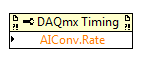
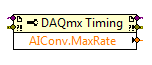
In addition, you can also set this rate through the DAQmx driver. "You can just use a property DAQmx Timing node' more' converted ' rate (or rate Maximum to determine the max).
If it's a problem, I advise to use a device with simultaneous sampling - let me know if you have any other questions. Take care!
-
Can't see the rise on a USB 6212 BNC channel time
Hello
I use an acquisition of data NI USB 6212 BNC to monitor the rise time. A single channel (AO0) is used to define a voltage all followed another channel (AI1). The problem I have is that I'm not able to see the rise on AI1 time, only a jump to the specified voltage.
I started to edit one of the material examples. Initially, I have connected the two channels via a BNC connector to BNC cable but thought I better with a simple circuit. I set up a resistance on a model and connected my channels accordingly with crocodile clips. Unfortunately, the result remained the same and all I see is a jump to the previous setting in tension (usually 0) to the new I entered with a infinite slope (vertical line).
I am fairly new to DAQ and plan to work with it for a while. The simple circuit will be expanded considerably in filter tests and other applications, but for now, I have to get the basics. I would appreciate help, that you can offer; only currently, my thoughts are if this could be a sampling problem (I put it to 400000 above) and if I may add a ceiling to slow things down. I want to get this to work, however, so I could develop by looking at rates of filters and sweep of the go-around.
I enclose my screws in the hope that they will help you decipher the problem. Have tried different combinations on DAQ Read and Write with single or multiple and 1DB/Waveform channel, although I'm pretty green in their functioning, without success.
In hoping to hear talk about you,
Yusif NurizadeYusif Nurizade,
What type of signal you generate on the AO line? The default value in the output array is a single element zero. That didn't exactly have a rise time!
To measure rise times sampling on the line frequency should be fast enough to get samples of several over the course of the rising part of the measured waveform.
The signal on the AO line will always be in the steps from one value to another. This is the way of working with D/A converters. 6212 specifications indicate a speed of 5 V / us. If two successive samples were 0 to 10 v it would take exit 4 move us from one value to another. Same samplng HAVE it line 400 kech. / s, you would get no more than an intermediate value and would not be able to measure the rise time.
Try putting an R - C circuit with a time constant on the order of milliseconds between connections AO and AI. You should be able to measure it.
Lynn
-
Difference between the name of the channel & Pulse Terminal (NI USB-6212)
I have a box OR USB - 6212 & on the pinout data sheet, it is said that the FREQ OUT default PIN is 40 & the signal name is PFI14.
I am trying to generate a pulse by FREQ OUT in c# & DAQmx by calling channel name "dev2/freqout". When I ran the program & attempted to verify the measurement using a multimeter, I don't have a reading of the PFI 14, but 6 PFI. When I tried to set the name of the channel for "Dev2/freqout", the pulse filled Terminal automatically textboox with control unit using the test panels & "/ Dev2/PFI6. When I started the program, I got multimeter reading out of the Terminal impulse.
Can someone please explain to me about this behavior?
Also if I want to write a program to read the pulses generated by FREQ OUT, should I wire PFI 14 to some CBC CTR or PFI6 to CTR CBC?
No explanations and answers are very aprpeciated.

Thank you
Hi Kasrus,
Thank you for that bring to our attention. I will study this question that you may have found an error in our documentation. My recommendation would be to use the PIN that works for you.
Thanks again for us help to continuously improve!
-------
Aaron F.
National Instruments
-
16-pin connector PCB Mount to NI USB-6212
I have the NI USB-6212 ending with scew and am looking for a connector that will allow me to plug an external PCB. If someone could provide a reference number, it would be greatly appreciated.
Thanks for the info. I have idendtified part number of Phoenix Contact 1862713 and the part number on the Bank Technology Inc. OSTV716315 as a correspondent to my needs. The OEM version is great, but as I already have version terminiated screws and this project justified with the purchase of a new Board of Directors, I'll stick with what I have. Thanks again.
-
Digital and analog inputs simultaneously - NI USB-6009 and NI USB-6212 - ANSI C
Hello
I'm reading at all times and at the same time analog and digital inputs. Digital and analog samples must be sampled at the same clock and acquisition should be started (triggered?) at the same time (I don't want, after some time, analog reception more digital samples - the opposite is also true).
I found an example (in C source code) "National Instruments\NI-DAQ\Examples\DAQmx ANSI C\Synchronization\Multi-Function\ContAI-Read dig Chan" and tried to run with two USB cards: NI USB-6009 and NI USB-6212. Unfortunately, the two results by mistake, as described below:
DAQmx error: the requested value is not supported for this property value.
Property: DAQmx_SampTimingType
You asked: DAQmx_Val_SampClk
You can select: DAQmx_Val_OnDemandTask name: _unnamedTask<1>
State code:-200077
End of the program, press the Enter key to exit-Is it possible sync analog and digital acquisition in the paintings?
-If so, how?
Thank you
Hello tcbusatta,
Two of these modules, USB = 6008 and USB-6212, support only timed software inputs and digital outputs. This means that you cannot define material timing (like finished sampling or continuous) for these modules. Digital lines can be retrieved or written once to each call DAQmx read.
This means that you will not be able to get any type of synchronization tight between the analogue and digital channels. You will need a Board such as the NI USB-6341 in order to synchronize the AI and DI closely.
-
Generation and acquisition of analog signals simultaneously on USB-6212
Hello, I am novice programmer DAQ trying to create (what I think is) something very simple.
I use a box NI USB-6212 and LabVIEW 8.5 is trying to generate a pulse train analog while recording a simultaneous analog input.
My first question is, is it possible?
Since I'm new to this, I use the DAQ assistant in LabVIEW. I can acquire a signal, I can also generate the desired signal, but I can't seem to operate simultaneously.
I have been successful in obtaining my program to work with both USB-6212, but I have to be able to do this with a single.
I have attached the block diagram and vi, I hope that's easy to answer the question, even if my research so far has left me empty handed.
Any help would be greatly appreciated!
Jon L
Hi Jon,
Well, first of all welcome to the DAQ programming! I took a peek at your code and published it with a device simulation very well, so I ran with the PCI 6251 card in my computer and he did not also get errors. Could you post the error code you get?
If I could figure out what is your error, I would say you encounter errors of buffer because it is too much overhead in the DAQ to wizards in the face of data rates. My suggestion would be to use the example called "Multi-Function Synch AI - AO.vi. This program can be found in the Finder for example of NOR (see Help"find examples in LabVIEW). "" It appears in the input and output material"DAQmx ' synchronization ' Multi-Function.
Can you give that a try and let me know how it goes? Thank you!
-
NI USB - 6212 BNC analog input impedance matching
I just ordered a case NOR USB - 6212 BNC DAQ (should be delivered soon). I want to use to measure HV signals using a probe of high voltage of 1/1000 I have.
Now, datasheet of the probe (not a lot of info) says it has an impedance imput 100MOhm. I suppose that it consists of a simple resisitve divider, and if the ratio is 1/1000, I wait so to have a 99.9MOhm resistance in series with a 0.1MOhm resistance. However, the data sheet also specify that the probe is designed to be connected to an oscilloscope with an impedance of 1MOhm. As this input impedance is very low compared to the low value of the separator of resistance resistance, so I guess that the real resistance at the level of the sensor values 99.9MOhm and 0.11MOhm (to obtain the 0.99 and 0.1MOhm when it is connected to the oscilloscope for 1mW).
Therefore, given that the impedance of the USB-6212 according to the datasheet, the analog input is > 10GOhm, I expect to measure higher to true alternative voltages when connected to the acquisition of data from 10%. This assumption has a meaning?
What would be the best way to get around this? Do a calibration and correct the values acquired in LabVIEW code? Or should I add precision 1MOhm resistance at the same time to the acquisition of input data to decrease its resistance to entry to the value expected by the probe?
Thanks for your help!
Since you have a range of 1000: 1 I guess you also need bandwidth (I have a TEK 6015 A
), so you need based on the impedance input, a complex value, means he must not only watch but also the ability to input resistance (1 M). demarcation of the field probes have usually some elements of toppings to match the probe and the input scope. RTFM of the help of the probe
BUT a more serious point is that with your probe, you have a very high resistance. And if you look in the specification of the 6212 you will find on page 2 by mistake ppm in logarithmic scale graph! and even 100 k source impedance it not shown.
So I'm afraid that a simple 1 M on the DAQ entry can work if you're only measuring DC, and only if you use a channel on the acquisition of data. A workaround is an amplifier separate buffer with an impedance of good entry corresponding to the specification of your probe and a low output impedance.
-
USB-6212: software problem timed task of analog input
Hi all
I have unexpected behavior using a USB-6212.
The code example shows that when I run in sequence two analog DAQmx to task, material entry first a timed, the second software timed, it happens that the first readings of data are all wrong and have the same value for all channels.
The labour code is the following:
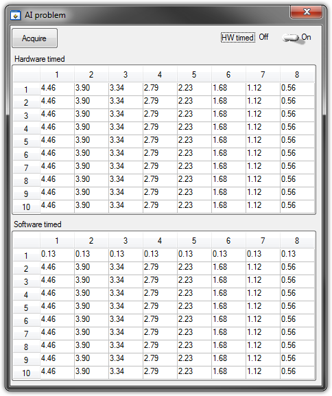
   GetCtrlVal(panelHandle, PANEL_HW, &Switch);

    if (Switch) {
//
// First Task: read 10 rows of values with hardware timing
//
        DAQmxCreateTask("", &htAI);
        DAQmxCreateAIVoltageChan (htAI, MX_DEV_AI, "", DAQmx_Val_NRSE, -10.0, 10.0, DAQmx_Val_Volts, "");
        DAQmxCfgSampClkTiming(htAI,"", SAMPLE_RATE, DAQmx_Val_Rising, DAQmx_Val_ContSamps, 1000);
        DAQmxRegisterEveryNSamplesEvent (htAI, DAQmx_Val_Acquired_Into_Buffer, SAMPLE_RATE, 0, RefreshCB, NULL);
        DAQmxStartTask(htAI);
            Delay(1.0);

        DAQmxStopTask(htAI);
        DAQmxClearTask(htAI);
    }
//
// Second Task:read 10 rows of values with software timing
//
    DAQmxCreateTask("", &htAI);
        DAQmxCreateAIVoltageChan(htAI, MX_DEV_AI, "", DAQmx_Val_NRSE, -10.0, 10.0, DAQmx_Val_Volts, "");
        DAQmxStartTask(htAI);

    for (i=1; i<=10; i++) {
        DAQmxReadAnalogF64(htAI, 1.0, 10.0, DAQmx_Val_GroupByChannel, AcqVoltRow, HW_AI_CHANNELS, &read, 0);
        SetTableCellRangeVals (panelHandle,PANEL_SOFT, MakeRect(i, 1, 1, HW_AI_CHANNELS), AcqVoltRow, VAL_ROW_MAJOR);
        Delay(0.1);
    }
    DAQmxStopTask(htAI);
    DAQmxClearTask(htAI);
A picture is worth a thousand words: analog inputs have been connected to a network of resistance have known values.
The upper table contains timed material acquisitions, the lower the software timed readings... as you can see it the first line is the set of values of 0.13, totally wrong
If the task of timed acquisition of software runs without the earlier (in my demo, that this can be achieved by the switch at the top right), the readings are correct!
Y at - it something I am doing wrong?
I also tried to run the program on USB-6009, but it seems to work properly.
[LabWindows/CVI 2010 SP1 - driver OR-DAQmx 9.4 - Windows 7 x 64]
This problem was corrected by NOR-DAQmx 9.5
324044 NOR USB-621 x task HAVE request returns incorrect data after erasing a task HAVE stamped
-
Can I feed 12VDC in a USB - 6212 BNC?
I want to follow a circuit that alternates between 0 and 12 VDC. The voltage level will be always equal to 0 or 12VDC.
I can feed this tension in one of the channels I my USB - 6212 BNC or going to fry something if I do. AI channels on the unit are only rated to +/-10V. I don't like to get an accurate reading of the voltage. I just want to see if the signal is high or low.
Thank you!
Hello
Here's the surge card for this map:
Surge protection (HAVE <0..31>, AI SENSE)
Device on... ±30 V for up to two pins of I
Device disabled... ± 20 V for up to two pins of IMy max current during the surge of input pin of ±20 State / I
So you can integrate 12VDC into your Board and not with precision the measure, but you should be in form do not damage the card. If you can turn the voltage down or use an external circuit to reduce the voltage in the specification of the Council, it would be better to ensure proper operation and extend the life of the Board of Directors to the extent.
-
Hello everyone once again.
With USB-6212, the current maximum disk said is 2mA. Let's say I connect two resistors 10kOhms and 1MOhms top. That means an average of principle?
This means that data acquisition does not have any potential to the terminals generate 1MOhms resistance?
Am a bit confused.
Will be grateful for your response.
see you soon,
Hi Navneet,
The only improvement to the SNR you could really make once inside LabVIEW is to apply a low pass filter to eliminate noise unwanted high-frequency. Digital filtering however within the software always induces some delay of constant phase between the response of entry and exit due to the transformation. The entry may be delayed, while the treatment occurs and then superimposed on a graph with the signal for the purposes of the analysis, but this is obviously not in real time. Is that what you mean by a change to the phase of the signal measured?
I've attached an example vi for you that shows how to use two different digital filtering of vi. Who is likely to be of interest is the zero-phase vi, which, as you should see overlays in phase with the original signal from the filter.
I would like to know if it was the kind of answer you were after that, I hope it helps.
-
I'm trying to control a solenoid TTL using a USB 6212 and LabView. I'm new to LabView and don't know if my code is correct. I'm also not sure which way I'm supposed to use. I appreciate all help.


Hi biomedP,
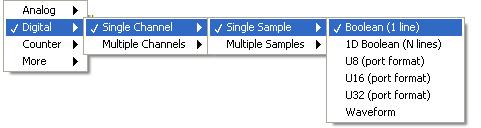
I had a look at your code, and it's a good start, but if you are simply trying to turn the TTL and you don't need a U16 to combat it. If you change your DAQmx, write to boolean (1 line), you can just write a real or fake (power) value to your solenoid.
I don't know to what extent you are in this project, but to develop it further you can also add a sort of loop or some control values. I am attaching a file named "solenoid % 20Control-1_mod [1] revised.vi", which should point you in the right direction.
You can also search in the help files for more information:
Step 1: Go to LabVIEW and go to help.
Step 2: Click on "Find Examples.
Step 3: On the tab browse on the tree table click "Hardware Input and Output" > 'DAQmx' > 'Digital Generation' > 'write dig Chan.vi.
Check out this example, it could solve other problems.
On the channel, just check where the solenoid is plugged into your 6212 and change the input on the VI to match.
Let me know if you have any other questions.
Thanks, Owen.S
-
I just got an error message at startup, which reads: execution of data path: to protect your computer, Windows has closed this program: name: request for logon Userinit, Publisher: Microsoft. My pc is under Windows XP SP2. I think that different multiple verisons of software "virus protection" began to appear in the Explorer. I know that they do not belong on my computer. I tried to close them, but they just kept moving forward. I'm trying to find some help to solve the problem. Moreover, when I close the window of Data Execution Prevention error message, I have my bottom, no other other icons for one of my programs are on the screen. Help... This can be corrected?
Thanks in advance.
Carter2009,
If you started having 'Magical' Antivirus programs to appear on your system that you do not install, then you are infected. Some people may be painful to remove, to others not so much. I recommend http://www.malwarebytes.org/ for malware protection and http://www.microsoft.com/Security_Essentials/ for antivirus.But now you're in a bit of a place. I download Malware Bytes and put it on a USB key. Then see if you can boot in safe mode and run MalwareBytes. If you're not in safe mode, take a look at this: http://support.microsoft.com/kb/318027
Hope these helps. QQ learn manage!
-
Time of safe operation for 8 hours a day
Hello:
I searched the forums for more information about the safe temperature for my Macbook Pro, however, many of them are either dated or not my model. I may have missed something mine so I apologize if this has already been answered.
I have an early 2011 15 "Macbook Pro with the following specifications:
- Intel Core i7 2.2 GHz
- 16 GB 1600 MHz DDR3 (after market - critical)
- AMD Radeon HD 6750 M 1024 MB
My CPU is still running between 65 c ~ 90 c and I fear that using my personal computer at work for 8 hours a day I'm going to be overloading it and I have to get a new.
Someone at - it present data on these older laptops? Everything I find is 2011/2012, so I don't know if it is current.
Thank you
Justin
These temperatures are absolutely perfect.
-
Satellite T135D-S1324 - no support for USB boot
Hello.
I buy this model (TOSHIBA SATELLITE T135D-S1324), I am a linux user, this model comes with ligthscribe player, I want install ubuntu on USB but to my surprise I discovered that there is no option for USB boot in the BIOS config.
Anyone know of a solution for this problem?
There's a kind of an UPDATE of the BIOS to activate the USB BOOT?
Thank you.
Post edited by: idposada
Hello
Usb drive before plug to turn your laptop and the Bios must recognize.
Maybe you are looking for
-
A bloggie as 1 (one) week and corrupted all my videos. Used video of recovery to recover memory card, BUT the video is corrupt and will not play with ANY video player. What a P.O.S. someone else had this problem?
-
So I just got a new laptop and I am trying to connect to my printer. I think he has connected all the beautiful and the printer will appear on my laptop. When I go to print something good, it is said that it is printing on my laptop (including indica
-
T400 - 6474CTO - key board problem
All of a sudden this problem occurred: n, b, space, arrow to the top right left suddenly stopped working. Working now and then, for the most part. KB has changed; the same problem. Any clue?
-
450 proBook G1: adaptors CA / CC
I am left handed and place my mouse to the left of my laptop. The adapter extends three inches in this space. s it y adapter replacement for this model with a 90 degree elbow?
-
I forgot the password of admin, need help. (unique number)
I have a problem with my computer. I have access to a guest account, but the account admin I need to access an administrator account on my computer, I have a guest account and I have access to cmd, but I cannto run administrative. I also use an ibuyp