Legend of Charts Flex customization
Is there a way to customize the chart legend < mx:Legend / > so that it displays items horizontally, but will come down to a second line if all items do not match?I blogged on this a few months ago:
http://blogs.Adobe.com/FLEXdoc/2008/07/customized_legend_layout.html
HTH,
Matt Horn
Flex docs
Tags: Flex
Similar Questions
-
How to control the direction of expansion of a XY chart legend
Hello
I adjust the number of plots by using the property node "Legend.Number of Rows (LegNumRows)" a XY Chart. I wish that the legend spread in the horizontal direction (right). I can choose the direction of expansion or growth of the legend on the front panel using the point of the scale on the right edge of the legend, similar to a table. So far so good. But the problem arises when the number of plots (LegNumRows) property drops to 1 or 0. What I mean is: I have 3 parcels on the legend laid in the horizontal direction. I run the application. Then I reduce the number of parcels programmatically (using the LegNumRows property node) to 1. Finally, I increase the number of plots again to 3. This time the legend grows / grows in the vertical direction. But I want him to stay in the horizontal direction.
Is it possible to do this?
As a side note, I discovered that the legend is in fact an array of clusters. I discovered by first customize the XY Chart, then customize the legend. But still no luck. Is there a way to programatically change the internal objects of a control to run?
I'm curious to know if there is any programmatic elegant solution to this problem. I appreciate any help or idea.
Thank you.
Burak Soysal
You can create a custom control and replace the control with your own image that corresponds to the background. Then place this control on extra legend items to hide. It's a little hard to describe so I made you an example:
When running, the cover of the legend merges with the background and the legend.
I did a Boolean, then went to advanced > customize. I copied then a section of screenshot that I took of the edge of a legend in to replace the normal Boolean image. Put this value just right, you can cover one end of the legend and if you disable the Boolean value the user will not be able to click on it. When you need more or less than the element 1 legend, you can hide the Boolean value programmatically.
It takes some tinkering with the photo (I used the paint), but I bet you can get it right if you spend time on it.
-
[FB4.6] compiler to appear SWF in Acrobat 9 Pro (Win7) settings
Hello world
I developed a dynamic PDF form to collect a quantity of data directly in an integrated system
Chart Flex (Flash Builder 4.6) incorporated as a SWF-rich media Annotation. The idea has been taken
a PDF file, I found, that incorporates a Flex chart, too, which also appears in Acrobat 9.
The two PDF documents, the original and mine, are in "PDF 1.7, Adobe Extension level 3
(Acrobat 9.x) ». But the mine did not show the SWF RMA in the PDF file. It exists and scrolling through the PDF document
It sometimes shows a gray box. So I guess there is a bad setting in Flash Builder at compile time.
Maybe someone has any ideas of what I should set?
I thank very you much.
Christian
I used the Flex SDK 4.6, while I assumed that there is no graphical component Flex SDK
3.6 because no cases showing in the library. But I was completely wrong and changed my
SDK for 3.6 and adjusted some namespaces within the Flex application. Now it compiles to
SWF Flash Version 9 instead of 14 and runs correctly in Acrobat 9.
-
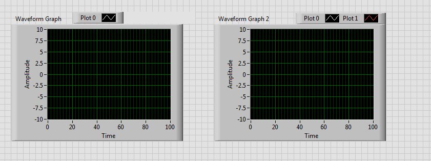
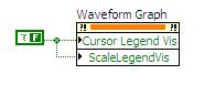
How to customize the context menu in the legend of plotting the graph of wave?
I am currently on the creation of a simulation of various control loops as educational objectives. Here, I have a chart in waveform to different signals. Now my question, how to customize the context menu in the track of the Waveform graph legend => when I click on 'image' behind the Plotnames one menu to open options where you can customize the color etc. or plotwidth. But students should not have access to these settings. How can I change or disable this menu? The context menu for the waveform graph, I've already customized by right click on table of waveform-Advanced online-online menu, but for the legend of conspiracy, I have not found this setting...
Thanks for your answers... I tried different things, but I don't see a solution yet :-(
See you soon
DCP
Hi, STC,
There have been a number of suggestions for change or disable the table , right-click menu, but I see that this does not affect the context menu of legend , which is what you ask for help with.
To prevent completely the menu right-click to work, you must disable the chart control entirely. You can do this by double-clicking on the chart and select Advanced Options > active state > disabled. This will prevent the operator to be able to generate a menu right click on the chart control.
If however you still wanted the table, make a right click menu to work, but the legend made a right-click menu will be disabled, I see two options:
1. draw a classic decoration square on the legend and the transparent color. This will prevent the mouse clicks to achieve the legend, and transparent it will not interfere with your user interface appearance.
2 use a Structure of the event to capture the event filter Popup Menu of Activation? for the chart control. You can then use the Coords property to determine if the mouse is over the legend or not. If this is the case, send faithful away? right Terminal. It will refuse the context menu when the user clicks on the legend of the plot.
-
Hello
I recently migrated my Flex 3.2 to 4.5 Flex application. I use a few cards in my application. I noticed a strange problem when I run my application with Flex 4.5. The legend of my piechart is not visible. The text is visible but the colors beside the text is invisible. The application works fine in Flex 3. Can someone help me in this regard.
Thanks in advance,
Nirmal Kumar Blues
Thanks for the reply.
in any case, I got the answer. My legend appeared once I commented SeriesInterpolate I used as an effect to the pie chart. Need to check how it works in Flex 4.5.
Thank you
Nirmal Kumar Blues
-
I am beginner with graphics in Flex, so bear with me.
I have 4 points I want to plot a graph, connected by lines (essentially drawing a rectangle). I want an x / y axis that displays-32 to 32 with graduations every 4 units in both sense (so -32,-32 through 32,32)
It may not even be adapted for a PlotChart, but he seemed to make the most sense for me.
My questions are:
1. how to define a range of min/max for the axes of the chart? Now it assigns automatically based on the plotted points, but I want it is constant.
2. How can I get lines connecting my 4 points?
The code, is so far:
< mx:Script > <! [CDATA]
Import mx.collections.ArrayCollection;
[Bindable]
public var savi:ArrayCollection = new ArrayCollection([)
{Section: 'Model 1', X:22, Y:14},
{Section: 'Style 2', X:22, Y:-23},.
{Section: Y: "Style 3", X:-21: 23}.
{Section: '4' Style, X:-21, Y:14}
]);
[]] > < / mx:Script >
< mx:Panel title = "graph" >
< mx:PlotChart id = "myChart" dataProvider = "{savi}" showDataTips = "true" >
< mx:series >
< mx:PlotSeries
xField = 'X '.
yField = 'Y '.
/ >
< / mx:series >
< / mx:PlotChart >
< mx:Legend dataProvider = "{myChart}" / >
< / mx:Panel >
Hey Ross,
I have writeen thereon.
'2. you must use LineSeries instead of PlotSeries to get the lines between points. You can also use LineChart instad of PlotChart if you use automatic color set for the series, but if you set the color manually is not metter. To fix the renderring lines see sortOnXField property for LineSeries. »
If you do not set this property to false, it will sort your data by X on the ground.
-
Hi all
I desperately need help. I am trying the chart data in Flex 2. I want several plotted series, each with its own dataProvider. I can not change the data that I use (it originates from a web service).
The Actionscript code that I wrote to process the result of the web service in order to plot the data is:
function loggerdataRPCResult(event:ResultEvent)
{
var result = event.result;
var series: Array = new Array();
for each (var LoggerData in the result)
{
var ls:LineSeries = new LineSeries();
ls.yField = "Date";
ls.xField = "Flow";
ls.displayName = LoggerData.LoggerId;
ls. Form = 'segment;
ls.dataProvider = LoggerData.FlowDataArray;
Series.push (LS);
}
loggerchart. Series = series;
}
Xml is the result returned by the web service:
<? XML version = "1.0" encoding = "utf-8"? >
"" "" "< ArrayOfLoggerData xmlns: xsi =" http://www.w3.org/2001/XMLSchema-instance ' container = ' http://www.w3.org/2001/XMLSchema " xmlns =" http://tempuri.org/ "> "
< LoggerData >
< FlowDataArray >
< FlowData >
< date > 2006 - 12-01 T 12: 00:00 < / Date >
< rate > 15 < / flow >
< / FlowData >
< FlowData >
< date > 2006 - 12-01 T 13: 00:00 < / Date >
< rate > 19 < / flow >
< / FlowData >
< / FlowDataArray >
< LoggerId > 1 < / LoggerId >
< / LoggerData >
< LoggerData >
< FlowDataArray >
< FlowData >
< date > 2006 - 12-01 T 12: 00:00 < / Date >
< rate > 2 < / flow >
< / FlowData >
< FlowData >
< date > 2006 - 12-01 T 13: 00:00 < / Date >
< output > 12 < / flow >
< / FlowData >
< / FlowDataArray >
< LoggerId > 2 < / LoggerId >
< / LoggerData >
< / ArrayOfLoggerData >
The script works to a certain extent - it creates two series in the chart and the legends of the series are visible, but no data is plotted in the chart area.
Any help would be very welcome.
Thank you very muchOK, so I got a quick mess on with what you provided and I came up with a number of things that can be the problem. First of all, you've been through your series and the axes x and y on. I mean, you got the Date on your axis horizontal, but assigned to yField of your series.
Secondly, I have not used the front axle desabscisses but it seems that the table should be assigned a dataProvider in order to make it work on categories. However, what I don't understand is why you use a desabscisses axis to represent the time. A DateTimeAxis is probably what you want? You just need to give a DateTimeAxis a parseFunction who takes the date strings in your data and their analysis in a Date object.
Thirdly, you also need the dataProvider to be LoggerData.FlowDataArray.FlowData. This is because LoggerData.FlowDataArray.FlowData gives you an array of objects with properties 'Fluidity' and 'Data', where as donors of LoggerData.FlowDataArray you an object without these properties (and therefore cannot be mapped to the axes).
So, in summary:
1 ls.yField = "Flow"; and ls.xField = 'Date '.
2. use a DateTimeAxis
3 LoggerData.FlowDataArray.FlowData as dp instead of LoggerData.FlowDataArrayHope that this brings you to a solution.
Graham
-
Hi all
I'm working on learning Flex for potential use in my business. Of course, to the first demo, I just want everything to look great and I have a problem with the tables.
I'm feeding a chart in an external xml file. The data is displayed correctly, but I can't get the legend labels to appear. I think that my xml is incorrect, but I don't know why. What I am doing wrong?Sure thing. You can link to the yField, like this:
>You will get a warning, as the liaison for that value used to detect changes, but this will work. Similarly, you could link it to any variable, perhaps that may be related.
HTH,
Matt Horn
Flex docs -
Rotate the Plot chart legend of XY
Is it possible to rotate the legend of the plot for the plot names letters run from the bottom to the top rather than in the whole of the operator interface?
The names of my plots are bigger and I need to show at least four plots at the same time. Put the scales to the right/left/above or below without rotating can cause a short XY Chart!
Any ideas for me?
Concerning
Waris K
Hello
I don't know if there is a native way to do it, but you can 'cheat' to do this:
You can move the table where the captions are, or even make the table turn into lines instead of the column.
Is the idea ok for you?
-
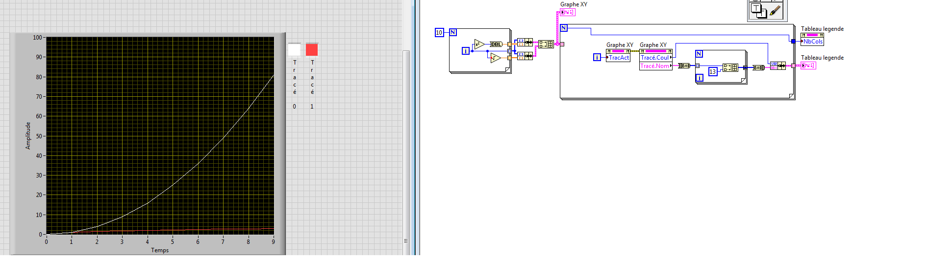
2D, legend, chart error bar XY, Multi draw help? Please modify the VI
Please READ THE ENTIRE POST and HELP!
Please help with this VI and make an instructive example for me and other novices like me who come through this typical example.
A typical problem of tracing data is the following: on the SAME plot (y axis = Amplitude axis x = time), draw curves Amp1, Amp2, Amp3,... from sample1, sample2, Sample3,...
In addition, it is a mistake1, Error2, Error3,... associated with Amp1, Amp2, Amp3,..., which must also be traced. In order to distinguish between these curves, we can use different
colors and show a legend that reads Amp1 (i.e. black), Amp2 (say red) and Amp3 (green for example). Then, the plot becomes complete and transmitting data very conveniently.
The attached VI made an attempt to trace Amp1 and Amp2 helps chart XY and 2D plot of error bar (to display error bars). There is a slight problem. The legend does not show what it is assumed
to show. Can someone solve this? If I draw two curves, the caption should show Amp1 Amp2, that if I drew three curves, the caption should show Amp1 Amp2, Amp3 and so on.
I don't want to see the default plot 0, draw 1 or whatever. Also, it would be nice to dynamically control the symbol, the color, the style of curve etc as we continue adding more curves in the plot.
Once this problem is solved, I know that I can easily extend to draw more accurate curves two dynamically. I could use for loops with shift registers, etc. to draw any number of curves on a single parcel.
Believe me, I searched for other positions and could not find a simple example like the one I posted here. I found a lot of examples have confused me more that helped me.
I believe that if this problem is solved in a simple way, many will find this informative example. So by helping me, you help a lot of other people as well!
Thank you in advance. Please see the attached files (VI and an example of data file I created only)
If you like graphic multiple curves (Y1, Y2, Y3, etc) with their respective error bars (Err1, Err2, Err3, etc.) on the same plot
Use the error Bar Plot (aka 2D bar error) and want the legend to display (Curve1, Curve2 Curve3, etc. or all what you want to call it),.
Please visit the following link:
http://forums.NI.com/T5/LabVIEW/A-simple-challenge-error-bar-plot/TD-p/1986755
For the use of XY graph, please check out the link in one of the posts above.
Thanks to everyone who has contributed to this.
-
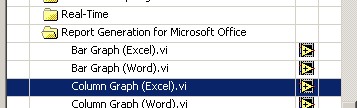
Hide the Excel using LabVIEW Report Generation Toolkit or active chart legend
Hello Eveyone:
I'm working on tool report generation in labview and creat excle report. I create the chart in the report, but I can't hide the chart legend or change the font size using the report generation tools.
I appriciate you guys time.
Thank you
Howdy!
What version of LabVIEW Report Generation Toolkit you use? Did you take a peek at the .vi LabVIEW example column chart (Excel)
and he looked at using the Excel insert graphical VI and Excel graphic Set do?
-
synchronization of a listbox and a chart legend
Hi all
I'm working on a code where I would be able to select/deselect 50 locations on a XY Chart. Due to the relatively large number of field names, it makes sense to place them in a scrolling caption or listbox.
Problem is (AFAIK), the legend of the parcel can not be used to * easily * plots do disappear and appear with a single click - must right click, go to colors and select transparent, etc. and then reverse the procedure to return the plot.
An alternative might be to use a list box 10 long lines as main indicator, then use some of its properties to create a dynamic chart borrowed from a second hidden chart legend. This legend of the plot to reconfigure its colors of dynamic line/symbol based on where the user is in the scrolling list box.
A problem I encountered is that the Label.ScrollPosition property is not going to write an indicator for me. See the code example.
Top row provides comments in the list box, but not enough information to do the job properly.
Any thoughts?
Kind regards
Ted
Hi to know the position of the list box item...
Try this...
> -
customize a pie chart in control
Hello
I'm trying to customize a button control. I created a graphic to replace one of the standard 'photo points' (accessible via the command Customize, double click on the chart).
The control I'm customization is circular. The graph I created is also circular, I saved as a. PNG or. EMF, with value white square background transparent.
When i 'Import from file' in BT import works well.
It's the image has always a square box shape (even if the background is transparent), then what makes the active control square area, which means that the control can be activated by clicking on the share of which is transparent (i.e. encompassing one of the corners of the rectangle).
Is it possible to create a graph that is round, or get the custom control ignore transparent areas?
- or who are all personalized with imported graphics rectangluar?
Thank you
Blue
In version beta LV 2009, I opened your VI and I can only change the value of the control when you click on the imported image. By clicking on where the arrow points or anywhere else in the rectangle but outside the black outline does nothing (so it works as you want). I don't know if it's because of a change in 2009 or something to do with my PC (XP on a virtual machine), but you should be able to find out soon enough when 2009 fate.
Alternatively, you can try for now is opening the custom control mode change and displacement of the shadow to the top of the z-order. Because the shadow is not clickable and has a 'hole' in the Middle it could work. It does not work here, but again, it is perhaps because of the new version.
-
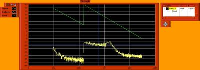
Get the picture (chart xy) cursor & draw palette/legend/graph label
Hi, I have a problem with the Image 'Get' invoke my xy graph node.
First, here is a screenshot of the result:
As you can see, is not only an image of the chart, but the chart & all of its items 'visible '. The only way I found to avoid is to disable all items by right-clicking on the chart before you click on the button "save the chart." Is there an another more convenient way to do so?
Thanks in advance
Hey,.
You can use the node property to pass the value false to the visible property of the legend under the click event to "save the graph...
And activate again the process to record is made...
Hope that should be
Concerning
HS
-
HI - another beginner question:
Following the tutorial, I created a graph. The graph has a small box to the right to go a legend for the different plots. (I would like to put a picture, but looks like that I do not have permission to do so).
The purpose of the chart is to trace thousands of points on a Cartesian plane. I got this job (sort of) with the PlotPoint() function. When I run the program, however, many quickly organized points exceeds the capacity of this legend (and won the start programme).
So: can I get rid of this legend somehow? On a side note, I am inefficient with this approach? Would it not be better to collect the points table and use PlotXY instead?
Thank you.
Hello
regarding the legend, open the respective popup panel by pressing the button caption on the graphic control panel change:
On top of this Panel, you will see a checkbox Show legend:
This box should do the job...

Regarding the choice of the route of functions: I would not draw 1000 individual data points, but use it rather PlotXY. Alternatively you can consider using a graph of the band instead of a graph, which allows you to add a data point after another


Maybe you are looking for
-
Performance problems with large Photo library size
Did anyone seen performance issues when the library becomes too great? I used to keep a few different libraries, since some of my libraries are already 1 TB. So, if I merge into one, the file will be 2-3 Tb when it's said and done. Anyone know if it
-
Re: Windows XP and Satellite T110-11J
Hello on a Toshiba Satellite T110-11J computer, I want to install Microsoft Windows XP. I wonder if the drivers installed on this site Web is for 32-bit or 64-bit system. Thank you for your answer
-
Hello I am using the following fuctions draw a graph in visual studio using the labview includes libs: InitCVIRTE(); NewPanel(); NewCtrl(); DisplayPanel(); SetAxisScalingMode(); PlotStripChart(); Can I change the size of the window to the background
-
Impossible to get Norton to uninstall
his party everywhere except when I'm in uninstall a program and it won't uninstall it, and I went need install avg
-
I have a BEFW1154 and Iam tring to hook it to a Telus SE567Modem, but have had no luck. I read until I'm confised!In my reading I came across a few post (not on this site)people having the same trouble.Can Q one, be done?Q two, it is in the firmware?