Linear system
Hi guys!
I'm working with electrical circuits and I need to know how to solve a linear system with more than 03 variables, such as a 5 x 5 systema.
How can I solve it?
Hi!, @Jucimar_C:
Try, if they serve, the Spanish language, the following examples video...
Tags: HP Tablets
Similar Questions
-
I use nD system no single linear solution.vi trying to solve two equations in two unknowns. I know how to do this.

But the question is how can I add a variable (that I don't want to evaluate non-linear system ND unique solution.vi) for example 'c' I want at the entrance of another VI. Similar to the way used in a formula node.vi, where you can add an entry.
One way to do this is to use the substitute Variables.vi. I have modified your VI to take the name of the parameter as an input ('c') and converted the numeric value to a string to create a substitution rule.
-
Solve this linear system HP50g
Hi guys,.
I am an engineer in electrical engineering and have to solve systems of linear equations on a regular basis, so that the functionality is very important for me. Everything works very well, 95% of the time but sometimes I meet systems that the HP50g doesn't seem to like. For example one below.
I want to solve for x, y, z and one in terms of V
V- 100000 x +is-100000 100000x= 0
-250000is-V+ 100000x100000z= 0
-250000z+ 100000one+ 100000y= 0
a+ 100000-250000z= 0
After these 4 equations is on the stack, I'm them in a vector by pushing {4} in the stack and then by pressing -> ARRY. Then I push the variables I want to solve for the battery, x, y, z and a and a vector of them. Then, I use LINSOLV to solve the system. However, when I do it this way, the calculator gives me an equation for x, an equation for y and 2 equations for z and no equation for s. I'm not sure what I'm doing wrong. Is there another way to do that would give me 4 equations, one for each variable I want to solve for in terms of V?
If my method to solve linear equations is somehow confusing, I basically followed this video
http://www.YouTube.com/watch?v=z802L29JyQE
Thanks in advance.Hello
Do not know exactly how you typed, so I'm being explicit just for some b:
Notes:
(1) as an equation is entered, use ' '
(2) it is preferable to use a comma to separate the real and imaginary parts
(3) explicit use multiply
If the entry will look like this:
'(4,3*X) = (4.7)'
For this simple equation and assuming that X is defined as an independent variable (reproduced by 'X' in the top middle of the screen), you can use SOLVEVX for this one: (No. 5 in S.SLV menu or F5 if you use soft-keys)
with "_Approx" uncontrolled, the answer is:
X = 7/3
with "vabout" checked the answer is:
X = (2.333333333,0) (although X is part of the imaginary number, it is himself a real number).
Kind regards.
-
non-linear system Solver more equations than unknowns
Is it possible to solve a nonlinear system with more equations than unknowns in LabView. I do a triangulation and data from several sensors, so I'm able to write 6 equations in order to get the 3 coordinates (x, y, z) as a solution. In LabView, I was able only to solve a system of 3 equations with this 3 unknowns, but I would use the set of 6 equations in order to obtain a more accurate solution, given that some measures can be noisy.
Thanks in advance
You can use the non-linear curve code to solve this problem. Consider the following system:
3XY + y - z = 12
yx + x ^ 2 + z = 12
x - y - z = - 2
Arrange to get 0 right side. x, y and z are the paramneters to be in shape. The entrance to the curved Fti.vi Y non linear will be an array of three zeros. Initial settings will be an array of three values, for example [1 1 1]. An example is attached.
-Jim
-
distance along an arc of an ellipse (nD of the nonlinear system (VI) .vi Solver)
I'm hoping to get help solve a problem, I came up against. I understand that what I'm asking requires little of your time, so I tried hard to do my due diligence before posting here. I appreciate you really any help I can get. I use LabVIEW 2014 Professional on Windows 7.
I removed all the details of the specific request, I'm working on that and tried to isolate the problem that is causing me problems.
I asked the problem below and I have attached a few instruction code (sorry, there is not bad) which represents my current solution (with the matter).
Problem: Given an ellipse (with a large and a small axe and a frame of reference), one distance and any point of the ellipse, calculate the end point on the ellipse, where the length of an elliptical arc between two points is equal to the distance to travel.
I'll rephrase the problem, but with physical values. Account required of an ellipse, centered on the origin, with axes of 10 mm and 8 mm, and a point of departure (5 mm, 0 mm); What is the point of endpoints on the ellipse after traveling 1 mm along the ellipse?
It seemed initially as a simple calculation (and that's a circle), but for an ellipse, the calculation is proving to be a bit more complicated and requires numerical computation.
Question: I was given a few python code that solves this problem and embarked on a solution of LabVIEW. Python code uses the scipy library optimize.fsolve function to solve one of the aspects of the problem. I'm not too familiar with LabVIEW screws available to do the equivalent, but settled on "LabVIEW 2014\vi.lib\gmath\zero.llb\nD non linear system Solver (VI) .vi" (my code still has some options disabled in the code). When I use this Solver VI, I don't always get the same response from this VI. Sometimes, he finds a root diskette and sometimes two. For points separated by less than half the circumference of the ellipse, it always 2 roots (in the sense and meter needles). Any ideas why the Solver does not always return 2 roots?
Current solution: my VI investigation takes two points on an ellipse (defined by a start angle and end angle) and calculates the distance between them along the ellipse. Then I take the starting point and the distance and try to calculate the end angle (that I can use to find endpoint). Run once, we usually find the right answer, but run 100 times it is often the answer 19. I should mention that I'm not 100% positive, there is no problems with the code used to support this calculation and I am open to any suggested changes or improvements, but currently problems is the inconsistent operation of the Solver VI.
Yet once again, I appreciate, is long and thank you for reading this well; I hope you find it as fun a problem as I do!

Chris
As promised, here's a working version of the code that I posted earlier. This code is always the right answer, where previously it sometimes not found the right answer. See my post above for details on what has changed.
Also, I was wondering at the start of what the LabVIEW equivalent to the python code that uses the function optimize.fsolve of the scipy library. I think the answer is
ND Single .vi Solution (VI) non-linear system
as its inputs match more closely and seems to perform similiarly. This is where I would start in the future and works well for the moment.
Thank you
Chris
-
model of dynamic system, which is the Solver
Dear Member
What labview mean by that word in this helpl http://zone.ni.com/reference/en-XX/help/371894G-01/lvsimconcepts/sim_c_ode/ labview
"" Because many models of dynamic systems consist of differential equations, you must resolve these differential equations".
"" Most of the simulations that you create in the LabVIEW Control Design and Simulation Module use solving of ordinary differential equations (EDO).
Best regards
Most of the linear systems can be modeled by linear differential equations, which can then be used to create a transfer function that describes how the system acts on an input to create output. Help is just stating that a Solver of ordinary differential equations (EDO) will serve as the default option, to solve the differential equations that make up the transfer function. It will solve the transfer function, probably composed of differential equations, for descrete time step, thus returning the step responses of the system for a given entry.
-
Friday for the nerd CS problem
I stumbled on what is probably a common problem and thought that some of super nerds here might have fun with this question:
take a (ascending) table of arbitrary values... that is to say {1,2,3,5,8,12,16}
now for any desired value, return a subset of table of values that SUM to the desired value. Elements can only be used once, obviously there are several solutions. As for the table above 8 would have 2 solutions: {3,5} or {8}.
My particular problem was not as arbitrary, so I was able to use a combination of thresholding and number to Boolean matrix to determine the value.
My instinct tells me to nested loops would work but messy, maybe a form any recursion could be better, or is there a way to solve this problem with a linear system.
Any thoughts?
It's the classic CS Knapsack Problem.
I guess a solution like this: put the element next to the table in the 'bag', as well as the index of this item. Then, you have three options:
-The sum of the cover is lower than the target. If so, increment the index table and repeat.
-The sum of the cover is equal to the goal. Add to the list of solutions, empty the bag, add to the index of the first element that was in the bag and repeat.
-The sum is greater than the objective. Remove the most recently added element, increment the index and repeat. If at the end of the list, remove the item next-most recently-added, increment its index and repeat.
If I have time later or over the weekend, maybe I'll post real code.
-
Discreet Integrator (control and Simulation Module) - LabVIEW 2015
Hey everybody,
I'm trying to drag the discreet Integrator on a block in 2015 of LabVIEW diagram. All other vi in the "range of discrete linear systems are draggable, but not the"discreet"Integrator." I noticed the same thing for the continuous Linear Systems Integrator. Anyone explain how to solve this problem?
Sincerely,
Lex
Lexicondi,
Unfortunately, these functions cannot be moved out of the loop control & Simulation. We support only discrete transfer, of State spaces and ZPK models function.
So, if you want the "discreet Integrator" outside of the SIM card, you have the following options:
one) to use the "discreet transfer function" as T /(z-1) (or any other type of discretization available in discreet Design continuous monitoring);
(b) you can develop your functions inside the control and the Simulation loop and then create a subsystem of her. The subsystem can move outside the SIM card also. Here, you can use any SIM function you want;
I hope that this should be sufficient for your application.
-
Dear Sir
I am a beginner in labview and I would like to solve two differential equations and field them over time:
DX1/dt = (G - K * x 1 (t)) /V (t)
dV (t) /dt = (1/((1-(((G-x1*(K-U))/(G-x0*(K-U)))^((U/(K-U)))-1))*U
G = 7.8
U = 0,166
x 0 = 132
VO = 432
K = 2.02
Could someone please help me and send the block diagram for these two equations.
The graphs of these two variables have to be reduced over time. The graph of X 1 is of exponential decay.
Hello Ahmad,
I made a simple example and put it on our community page. This example uses our ODE solver vis LabVIEW comes with 8 built in ODE solvers. These are all linear system solvers. It seems that your equations are not linear. I suggest using the LaPlace transforms to solve equations.
-
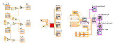
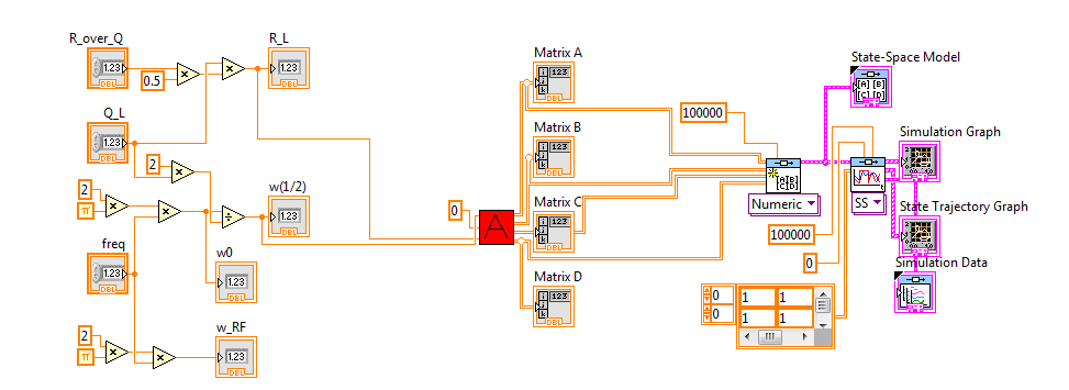
(Control design and Simulation) State-space block don't gives result
I tried and tried but failed to get the State-Space block module to give me a graph / output.
I have no idea what the problem is and I hope someone can help me. Numbers and calculations work in Matlab (Simulink) but I can't simulate in labview.
Anyone have any ideas?
The problem is that you are assuming that LabVIEW runs left to right. Stream does not work that way. Your code like this:
does not say LabVIEW He must run everything from left to right. What happens is that it runs to the 3 'island' of the code in parallel and, in this case, it will be "empty" values You must remove the local variables to do this job and paradigm of data flow runs your code from left to right, as you wish. Here is the code:
Also, one last thing. Your contribution to the Simulation of the 'linear' CD is equal to zero all the. This means that you try to input zero linear system, which will give you a result zero in the answer. You probably don't want that since zero as input gives you more information. If you want to see how system will reset after initial conditions, you must use 'CD Initial Response. " Or you need to change the input to the system signal. Please study this shipping example to understand how to use the linear Simulation and initial response:
C:\Program Files (x 86) \National Instruments\LabVIEW 2012\examples\Control and Simulation\Control Design\Time Analysis\CDEx time domain analysis
I hope this helps...
-
FIRST HP: Solving a system of linear equations with a parameter
Hello
I know how to solve a system of linear equations by using a setting by hand but I don't know how to set up in the calculator.
Can someone please help me solve the system of linear equations below with a 'p' on the first HP Calculator next parameter?
2 x + 8z = 26
4 x-4y-14z = - 38
8 x - 4y + 2z = 14
The answer to the above equations is:
x = 13 - 4, =(45-15p)/2, z = p y p
Thank you
Arthur
Hello
What you're trying to solve is not really a system of equation with a parameter, but you try to solve a set of 2 equations with 2 variables (x and y).
The case solve command can do for you.
According to the CASE, type:
Solve ([(2*x+8*z) = 26,(4*x-4*y-14*z) = - 38,(8*x-4*y+2*z) = 14], [x, y])
Come in
and the calculator will return
{[-4 * z + 13, 15/2 * z + 45/2]}
which is what you want.
Cyrille
-
Hello
Does anyone know if there is such AS classes or functions to solve systems of linear equations? On the form A * x = c. A is a square matrix, x is a vector of unknown, and c are constants.
In other words, a system of equations with a number of well-known (1-5) and an equal number of equations.
Here is an implementation of the elimination, Gaussian, that you can use. There is no error checking included:
package com.kglad {}
public class Gaussian_Elimination {}
public void solveF(a:Array):Array {}
for (var pivotCol:int = 0; pivotCol<>
a = pivotF(a,pivotCol);
var factor: number;
for (var row: int = pivotCol + 1; row)<>
factor = a [row] [pivotCol];
for (var _col:int = pivotCol; _col)<>
a = [line] [_col] has [pivotCol] [_col] * factor;
}
}
}
Return echelonF (a);
}
private void pivotF(a:Array,pivotCol:int):Array {}
var maxAbs:Number = 0;
var maxRow:int;
for (var row: int = 0; line)<>
{if (Math.ABS (a [Row] [pivotCol]) > maxAbs)}
maxRow = row.
maxAbs = Math.abs (a [row] [pivotCol])
}
}
pivotCol line swap with maxRow
var tempA:Array = a [pivotCol];
normalize the maxRow
var number: max = a [maxRow] [pivotCol];
for (var i: int = 0; i<>
a [maxRow] [i] / = max;
}
[pivotCol] = a [maxRow];
a [maxRow] = tempA;
return a;
}
private void echelonF(a:Array):Array {}
var years: Array = [];
var last: int = a [0] .length-1;
for (var row: int = 0; line)<>
var term: Number = 0;
for (var num:int = 0; num<>
duration = [line] [last-num-1] * and [num];
}
end += [line] [last];
ans.push(Term/a[Row][Last-Row-1]);
}
Return ans.reverse ();
}
}
}
-
HP 40GS systems of linear equation with parameters
Hello
I'm in the learning curve of the HP 40GS - a very interesting tool.
Is it possible to solve systems of equations with parameters, for example:
A * X + Y = 2 * 12
5 * X - 3 * A * Y = 5
HP 50 g, this isn't a big deal, but with HP 40GS I don't have an idea so far.
If this is not possible, it will be possible if I have a third equation (so 3 equations in 3 unknowns)?
Thank you very much in advance,
Joachim
P.S.: So far, I feel very comfortable with the HP 40GS and menus!
----------------------------------------
I am not a member of the HP Calculator development team - unfortunately!Hello
now, I found a way to calculate the systems of equations with symbolic coefficients:
See the document: http://www.hp.com/ctg/Manual/c00829737.pdf to page 346ff
With the command 'linsolve', it is possible to calculate with more unknown than equations.
I hope this helps anyone with the same or close problem.
Have fun with your calculators and do not hesitate to write other ways of calculations.
Greetings,
Joachim
-
Calibration system as a solution of nonlinear equations
Nice day
The challenge of the day is to provide a calibration for a release of the accelerometer, expressed as a binary value.
I have an accelerometer whose operating range can be set (±2g, ±4g ±8g). The accelerometer itself then generates a binary value to 16-bit resolution. Therefore, only 2 ^ 16 value (0-65535) represents an acceleration value of which depends on the lines we have.
So we make the asumption that the response is linear, which allows us to claim:
Acceleration = scale x value binary + Offset
I have three axes of a value of data, accelerometer A, B and C. If I hold the stationary accelerometer, the only thing that I should be reading is acceleration due to gravity, g. It makes me of the relationship
(A) ^ 2 + (B) ^ 2 + (C) ^ 2 = g ^ 2
Since then, in any direction, the magnitude of the combination of all the three readings of the acceleration must be the gravitational acceleration (and that shouldn't change little matter which side you happen be pointing the accelerometer).
What gives me, then, is a non-linear relationship of 6 variables (scale factors three and three shifts). I should be able to take six measures in an arbitrary orientation that will give me six output values of each had. Then I should be able to get out the scale factors and offsets for each accelerometer, either in terms of g or with respect to which, in my opinion, g is.
So, my question is how can I get Labview to do this? I see that there is a tool to solve linear equations, but I don't see one appropriate for the non-linear case. I'm also very comfortable believing that I'm just missing it :-)
Thank you!
Since the help file detail to the nD nonlinear system Solver.vi:
Formula Variables VI analysis
The formula analysis screws accept only the following variables:

Note These same variables to specify the description of the chain of the formula for the adjustment of non-linear curve VI. a, a0,..., a9
b, b0,..., b9
.
.
.
z, z0,..., z9
For variable and function names, only lower-case letters are allowed. Screw interpret case as errors.
1. I found this by opening the Panel before the nonlinear Solver VI when executing your VI. The error information said that there was a problem with the formula.
2. I replaced the Scale__ and Offset__ variables with a0, a1, b0, b1, c0 and c1 in tables X and f (x).
3. I have expanded the values start and end - 10 and 10.
This seems to work much better. At least it runs.
Lynn
-
Want to use Lock-in detection with a linear detector with diode bars
Hi people,
I work with OR lock virtual amplifier to build a detection system that uses a linear led strips detector to measure the effect of an electric field on the spectrum of a molecule absorption. Traditionally, this technique was carried out using a single photodiode detector connected to an external amplifier of detent and the absorption spectrum was analyzed using a spectrometer. The lock would demodulate the signal of interest based on the wavelength. In my setup, I acquire any range (all wavelengths) simultaneously to speed up the experience and improve S:N. to do this, I use a spectrometer OOptics USB2000 + and NI virtual LIA. Each element of the photodiode array, then acts as a unique photodector calibrated to a specific wavelength. I want to demodulate the signal of interest of each element of the matrix of the photodiode.
After reviewing several of the messages on this forum, I start to worry if my setup actually work. So far, I have seen that everyone uses a detector single channel connected to a card scanner of some sort, which also acquires a reference signal. Phase delays would come mainly from electronics and cable lengths. In my setup, the detector is digitized by the 2 MHz ADC in the spectrometer OOptics and my digitizer OR is only to measure the experience reference signal. Because two ADC of separate instruments are used, this prevents the use of the vLIA? My intuition tells me that don't know, but I am relatively new to the use of detectors photodiode array for this purpose.
Any help would be greatly appreciated.
Timchem
Tim,
Now we are getting somewhere.
The effective sampling rate is about 70 Hz. Unfortunately, the time is probably metered software, which introduces additional jitter at the time of each data set. Sampling a signal to the Nyquist rate only gets you the minimum information on this signal and certainly produced very little significant phase information.
Given that the intensities of the pixels are measured at the same time, you have no worries for the phase shifts between the pixels.
Question about the synchronization: the spec introduces a measure whenever it receives a TTL pulse? Integration of 1 ms, then send 2048 data points, then wait for the next pulse? Assuming that's what he does, then you have a chance to lock a verrrrrry slooooow amplifier.
It would work something like this. Setting the sync generator to produce a measure trigger pulse every ms T, where T > 13 + 1 ms. Suppose that T = 20 ms (FLA = 50 Hz) to keep simple mathematics. Sets the modulating frequency to 1 Hz. Then you get 50 samples per period of modulation, or sample all 7.2 degrees.
Now I need more. You indicate that your alternative signal is microvolts. What is the significance of the component continues? The relationship between these two signals is the signal to noise ratio. A quick glance on Ocean Optics web site indicates that dynamic range for a single purchase is 1300: 1, which seems low for a device with a 16-bit A/D converter. This must be the limit of the photodiodes to an integration time specified. If the signal is really limited to this range, you can get into trouble. The lock-in amplifier depends on some signals actually being there, just smaller than the noise. In this case the limitations of photodiodes or the processes scanning spectrometer, it is possible that there are really no signal there to extract.
If your signal is a quantity equivalent to 10% of the dark current, you must get a signal you could accurately measure on average for about 100 cycles of the modulation frequency (1 Hz) to start. Your samples are stable for 2 minutes or more?
A different instrument may be the best bet.
Lynn

Maybe you are looking for
-
Orbi relies on a Cloud Computing service?
Orbi relies on a cloud service operated by Netgear (or someone else) in order to operate? I prefer a router that works without the need to 'phone home' to its installation or ongoing operating manufacturer.
-
Copy of Sansa e260v2 on hard drive
I connect my Sansa e260v2 in MTP mode. In Windows Explorer (Windows XP SP2), I see the structure and the files from the internal memory. I select a file, right-click to copy, navigate to a folder on my hard drive, make a right click Paste... and noth
-
Push the registration mail not received
I have the registry for the push with the name of the application as service "BeckMan Coulter". There is still no mail came. can someone me check for this? wait for 3 days. Rognard BlackBerry dev BlackBerry ID: [email protected] Favorite e-ma
-
How to get the time of the device
Hello I'm developing an application in which I send location of the device in lat, long for every 10 minutes. I want to send some time also with lat, long. This time must be peripheral situation updates for every 10 minutes. Can someone tell me how
-
Cisco TMS device virtualization
We will virtualize the TMS device to a virtual machine, but had a few questions regarding the parameters: 1. are there things that I have to watch what is using the same IP address? Let's change the name of TMS 2. do I need generate a CSR that is new