Maximum nodes in a segment of REP?
What is the IE-3000-4TC maximum switches that can be used in a segment of REP?
Thank you
David
Hello David,.
Our tests of development has tested 32 knots during our tests of performance/scalability. That being said we have several clients who have more than 100 devices in a ring without problem. There is no hard/FAST rule on exactly what is supported and not supported. More switches in the ring will equal more slow time of convergence and the response to a failure. Even with 100 devices in a ring time of convergence is always substantially improved over the RSTP.
-Matt Blanshard
Cisco TAC - switch Lan
Tags: Cisco Network
Similar Questions
-
Impossible to activate REP on 3750 x IOS 15.2
I am a neophyte on the IOS in general, and accepted with gratitude the 3750 x in particular, so any suggestions. I am trying to configure REP on a new 3750x24P-S that has been flashed to 15.2 IOS universalK9. The message I get is 'conflict with current switchport mode '. As I do I start to wonder if this is related to the license level, that I am more research. The ipbase shows as permanent, but the ipservices always present in evaluation mode. Some of the notes I've seen here seemed to suggest that ipservices should apply because you would be able to change the settings for the port, which * might * apply here.
I tried to accept the EULA and it seems to work, but a reboot of the switch always displays ipservices in eval mode. Subsequent attempts to accept the EULA now do nothing, as if it has already been applied. So, any suggestions as to why I can't configure my ports for REP? Other than the initial installation, the switch is now in default values.
Thank you!
James,
You have configured the interface as a trunk of layer 2-
Only trunk ports are supported.
REP of understanding
A segment of REP is a chain of ports connected together and configured with a segment ID. Each segment consists of the standard ports (no edge) segment and two edges that are configured by the user. A switch can have no more than two ports in the same segment and each segment can have only a single external neighbour. A segment can go through a shared medium, but on any link two ports can belong to the same segment. REP is only supported on the Network Layer interfaces 2
Figure 24-1 shows an example of a segment composed of six ports over the four switches. Ports E1 and E2 are configured as edge ports. When all ports are operational (as in the segment on the left), a single port is blocked, the diagonal line. When there is a failure in the network, as shown in the diagram on the right, the blocked port returns to the State of transmission to limit disruptions to the network.
Kind regards
Alex.
Please evaluate the useful messages. -
I want ot know something moew on
shmsys:shminfo_shmmax
can someone explain the same above...Shared memory is exactly that - an area of memory that can be shared between different processes. Oracle uses the shared memory for the implementation of the SGA, that should be visible to all database sessions.
Semaphores can be regarded as flags (where their name, semaphores). They are either on or off. A process can turn on the flag or turn it off. If the indicator is already activated, process trying to light the indicator go to sleep until the indicator is turned off. Wake up, the process will try will turn the meter on, perhaps suceeding or maybe to sleep again. This behavior allows semaphores to be used for the implementation of a pilot of waiting after - a system where the process can wait for events (i.e. wait for turning on a semphore) and after the events (i.e. by turning of a semaphore). This mechanism is used by Oracle to maintain the concurrency of the LMS, since it is writable by all attached processes.
1. a segment
2 neighbor multi-segment
3 non-voisin multi-segment
When you try to assign and set the memory shared to the LMS, it will try each in the order defined above, until it succeeds or triggers an error ORA. On the other, no mortals, errors, Oracle has simply cleans and try again using the next memory model. The entire SGA must be part of a shared memory, so the total amount shared memory allocated under any model will be equal to the size of the SGA (SGASIZE).
SHARED MEMORY ALLOCATION
1. a segment:-a segment model is the simplest and the first model tried. In this model, the SGA is a single shared memory segment. Oracle tries to allocate and set a shared memory segement of size equal to the total size of the SGA. However, if the SGASIZE is greater than the configured PACKAGE, it will fail of course. In this case, the CMS should be placed in several shared memory segments, and Oracle of the product for the next model of the SGA memory.With several segments, there are two possibilities. The segments can be attached contiguously, so that it seems to be a segment of memory shared, or non-contigu, with gaps between the segments.
2 neighbor multi-segment - in the segment model contiguous, Oracle simply divides the SGA in SGASIZE/SHMMAX (rounded) of size SHMMAX segments more another segment of size SGASIZE modulo SHMMAX
3 non-voisin multi-segment: once determined the number of segments and their sizes, Oracle, then allocates and tie the segments one at a time. first of all the fixed and variable part or segments, then do it again block buffer segment, then the block buffer PB or segments. They will be attached not contiguous.
At this point, we have to be attached to the whole SGA or returned an error ORA. The total size of the attached segments is exactly SGASIZE; no space is lost. Once Oracle's shared memory attached, Oracle proceeds to allocate the semaphores as it requires.SHMMAX = the maximum value of the segment shared memory =.5 * size of the
physical memorySHMMIN = shared memory segment size = 1
SHMMNI(5) = maximum number of shared memory on system identifiers = 100
SHMSEG = maximum number of shared memory per process = 10 segments
Check it out in detail on
http://www.orafaq.com/node/8
-
WSN-3202 sensor supply voltage
I want to know the amount of voltage that provides power to the sensor of WSN-3202. In the datasheet, it is written that it provides 12.6V. But if I operate the WSN-3202 battery, then to the maximum node, it can get 6 v battery of four. then, how it may be able to give where driven by battery 6V 12V sensor? Help, please.
I have another question, with regard to my knowledge, the node not send data continuously, when gateway will call it, send it and so it will save battery by making it on after call from bridge - this idea is good? If it so, then when the node is in mode 'sleep' (do not send all data, connection) will give no voltage sensor - it should be? is it? then when the gateway do call, connection, gives power to the sensor. but he will do a delay to give power to the sensor and collect sensor data right? will this affect?
Hello, KJV,.
Must have lost this reply in my email. My apologies that I answer all the time!
The sampling interval is when the wake of nodes of samples, the front-end (IA and DIO) and transmits that data back to the gateway. This is done on the sampling interval, so if your sampling interval is 5 seconds is how many times it happens. The node is in standby the rest of the time. Sampling and sought takes ms.
The time setting power sensor is for you to specify if you want to than the power to allow line. If, for example, if your setting is 250ms for sensor supply and our sampling interval is 5 seconds:
1 start time = 0
2. the sensor works in 4.75 seconds
3 example of front end and transmit data to 5 seconds
4 node falls asleep to ~5.1 seconds
Let me know if this clears things up for you.
Again sorry for the late reply.
Corby
Support Engineer produces WSN R & D
-
Services of files in Microsoft Clustering with failover in ESXi 4.1
Helllo,
I have a virtualization environment with 5 hosts ESXi 4.1 on location A and two hosts ESXi 4.1 location B, all with high availability, which is the host 7 ESXi 4.1 are highly available.
I need to set up a file of Microsoft with Failover Clustering in ESXi 4.1
I want to create a file from Microsoft with Failover Clustering with 3 VMs that are 2 VM on a location and 1 VM on site B.
Geographic VM cluster is supported by vmware?
What is the maximum nodes in the cluster in guest virtual machines?
Thank you
jVidalll
Welcome to the community,
Only 2-node MSCS is supported in ESX (i)
Take a look at http://kb.vmware.com/kb/1004617 for links to MSCS documentation.
André
-
Max_size parameter in the dba_tablespaces
Hi all
I'm on environment of 11G oracle using SPARC machine.
I created a tablespace yesterday with the following query:
It was created, but with that I found a MAX_SIZE parameter value: 2147483645 when I questioned the tablespace using select * from dba_tablespaces where nom_tablespace = 'XXXX_DATA ';SQL> CREATE TABLESPACE XXXX_DATA LOGGING 2 DATAFILE '/XXXX/XXXX/f_data01.dbf' SIZE 512M REUSE, 3 '/XXXX/XXXX/f_data02.dbf' SIZE 512M REUSE, 4 '/XXXX/XXXX/f_data03.dbf' SIZE 512M REUSE, 5 '/XXXX/XXXX/f_data04.dbf' SIZE 512M REUSE 6 EXTENT MANAGEMENT LOCAL UNIFORM SIZE 10M;
I did not specify this argument. Other tablespaces that exist have this parameter the value empty.
What is the importance of this parameter. Is it possible altered, set empty?
What happens if the size of the segment increase beyond this MAX_SIZE?
I checked on google, and he told her:
Maximum size of the max_size default NUMBER of segments.
(http://download.oracle.com/docs/cd/B28359_01/server.111/b28320/statviews_5054.htm).Hello
Max_size defaults to the maximum size of the segments. the default size is unlimited.
Max_size is new column the DBA_TABLESPACES in 11g.You can change it.
SQL> select TABLESPACE_NAME,MAX_SIZE from dba_tablespaces;TABLESPACE_NAME MAX_SIZE
------------------------------ ----------
SYSTEM 2147483645
SYSAUX 2147483645
UNDOTBS1 2147483645
TEMP 2147483645
USERS 2147483645
EXAMPLE 2147483646
6 rows selected.SQL> alter tablespace example default STORAGE(maxsize 10g);
Tablespace altered.
SQL> select TABLESPACE_NAME,MAX_SIZE from dba_tablespaces;
TABLESPACE_NAME MAX_SIZE
------------------------------ ----------
SYSTEM 2147483645
SYSAUX 2147483645
UNDOTBS1 2147483645
TEMP 2147483645
USERS 2147483645
EXAMPLE 1310720
6 rows selected.SQL> alter tablespace example default STORAGE(maxsize unlimited);
Tablespace altered.
SQL> select TABLESPACE_NAME,MAX_SIZE from dba_tablespaces;
TABLESPACE_NAME MAX_SIZE
------------------------------ ----------
SYSTEM 2147483645
SYSAUX 2147483645
UNDOTBS1 2147483645
TEMP 2147483645
USERS 2147483645
EXAMPLE 2147483646
6 rows selected.
HTH
ScottPublished by: Scott Zheng on April 20, 2011 11:04
-
Performance of the LOD approach for network analisys
Hi all,
I opened the new thread to talk about the performance of the LOD approach for the analysis of network using Java APIs as the continuity of this thread:
Partitioning of the network using the API of LOD
I remember you that:
-I'm using Oracle 11 g R2;
-My Network 7.817.372 links and 6.662.079 nodes (network);
-The table of links LINK_LEVEL is set to NULL;
-J' partitioned network with these procedure:
partition:
Sdo_net.spatial_partition EXEC ('ITALIA', ' ITALIA_PART$ ', 10000, 'WORK_DIR_ITALIA', 'ITALIA_PART.log', 'a', 1);
and for the blob of the partition:
Sdo_net.generate_partition_blobs EXEC ('ITALIA', 1, ' ITALIA_PBLOB$ ', true, true, 'WORK_DIR_ITALIA', 'ITALIA_PBLOB.log', 'a');
-J' uses LOD Java API for the analysis of network with Netbeans IDE. I took the code of the network NDM_tutorial of Hillsborough.
My first analysis is the calculation of the shortest path between two extreme knots (about 1,500 km of distance) and two near knots (about 80 km of distance) using the algorithm of Dijkstra and AStar.
I did the following tests on the execution time of the shortest path calculation:
(1) with the score of 10000 maximum for the partition nodes (log file I read that generated the 1024 partitions with level 1 link):
-between two extreme knots, approximately 1 minute and 50 seconds.
-between two near knots, about 20 seconds.
then I re-run two previous procedures where I changed the value of the maximum nodes for the partition and I did other tests:
(2) with the score of 15000 maximum for the partition nodes (log file I read that have been generated 512 partitions with level 1 link):
-between two extreme knots, approximately 1 minute and 50 seconds and sometimes it comes out of memory
-between two near knots, about 20 seconds.
(3) with maximum score 5000 nodes for partition (log file I read that have been generated 2048 partitions with level 1 link):
-between two extreme knots, approximately 1 minute and 50 seconds and sometimes it comes out of memory
-between two near knots, about 20 seconds.
(4) with the score of 2000 maximum for the partition nodes (log file I read that have been generated 4096 partitions with level 1 link):
-between two extreme knots, approximately 1 minute and 50 seconds and sometimes it comes out of memory
-between two near knots, about 15 seconds.
I think there is a problem because I expect lower execution times (maximum 5-6 seconds for extreme nodes).
Even change the maximum number of nodes to partition the run time does not change much.
I remember you that with memory on Oracle 10 g 2 approach the execution time for each calculation between two nodes is about 4 minutes and he sometimes goes out of memory. With LOD on Oracle 11 g 2, the execution times are reduced but are too long for me.
Now, my questions are:
-@Jack Wang: (if you read me) do you know what are the run time for the calculation of the shortest path between two nodes for USA network (about 1500 km away)? I remember that you used the LOD for the United States (56 million bond and 20 million nodes).
-Do you think I have something wrong? How can I help reduce the execution time of network analysis?
If you need more information just ask.
Thanks to all in advance much.Could you please try setting the last input parameter 'regenerate_node_levels' true when calling sdo_net.generate_partition_blobs?
EXEC sdo_net.generate_partition_blobs ('ITAI11_METERS', true, true of 1 ' ITAI11_PBLOB$ ', 'WORK_DIR_PROVA', 'ITAI11_PBLOB.log', 'a', false, true);
EXEC sdo_net.generate_partition_blobs ('ITAI11_METERS', 2, ' ITAI11_PBLOB$ ', true, true, 'WORK_DIR_PROVA', 'ITAI11_PBLOB.log', 'a', false, true);
Please let me know if it makes a difference? -
How to set the property node maximum xscale for several scale XY Chart
Hello
I use a graph XY with three X axis and three scales of axis Y to draw the three sets of data. This works well.
What I do now is to set the Xscale.Maximum property node for one of the x-axis (the other two autoscale). If I click right in the (Create Blockdiagram; Node property; X scale; Maximum) I can not choose what x-axis I want to put the Maximum for.
So my question: how to select a specific axis allows you to set the XScale.Maximum property node when having several axes?
Thank you for your help, any suggestions are appreciated!
Hello
After some more research and experimentation, I found that using the scale property X Active I can determine/set for which the XScale.Maximum Xscale is used.
This solved my problem.
I hope someone else can save themselves a few hours with this thread!
Thank you
-
Number of nodes in the Group Rep
Hi all
All Rep groups have the same number of storage nodes.
But we can add or remove nodes as administrative task.
Does this mean that we can have Rep groups with a different number of storage nodes?
Thank you.user962305 wrote:
Hi allAll Rep groups have the same number of storage nodes.
But we can add or remove nodes as administrative task.
Does this mean that we can have Rep groups with a different number of storage nodes?Generally, no. However, if a node goes down either because the system or media failure, you can replace it with another node. But change the replication factor is not allowed in this release.
Charles Lamb
-
RAC nodes on two different network segments, what can go wrong?
Two-node RAC, what are the disadvantage if both nodes are on different network segments?
So the two node will be have a public interface on different segment, but interconnection will be on the same segment.
The two nodes have the same gateway and two network segments goes to the same switch.
It's Solaris, Oracle 10 g (10.2.0.4)Hello
Public IP addresses and virtual IP addresses must be in the same subnet.
This is necessary because the VIP - IP (two nodes) should work on two public networks.
Recently I've set up RAC extended with diferent networks (subnet). When all nodes is all that is very well. But when a node down, clusterware node gel survive because he trying vip - ip (different subnet) node configuration on the node down to survive.
Kind regards
Levi Pereira -
How to limit the maximum children to a node that contains different types of node
Hello
I have the following XML:
<categories>
    <category id="hsp">
        <cardUsage id="hsp.approvals">
            <tabUsage id="hsp.approvals.puListing"/>
            <tabUsage id="hsp.approvals.puDashboard"/>
        </cardUsage>
        <cardClusterUsage id="hsp.someCluster">
            <cardUsage id="hsp.someCluster.approvals"/>
        </cardClusterUsage>
    </category>
    <category  id="psb">
    </category>
    <category  id="pfp">
    </category>
    <category  id="cx">
    </category>
</categories>
I need to put a restriction on this category of node cannot have more than 16 children (nodes of cardUsage + cardClusterUsage nodes).
The way I thought to achieve this, use a new use as a child of the category node. I could put on its use maxOccurs at 16. And then in use use the XS: Choice to choose between cardUsage and cardClusterUsage. And the maxOccurs 1.
Please let me know if there is a better way to do it. Or if you see the flaws in my proposal.
Thank you for your time in advance.
Matt.
The order of the child category matter?
If this isn't the case, you can directly set maxOccurs on 16 in the xs: Choice:
-
I can't get flv (YouTube video) larger files that 1740bytes of Firefox12 in Windows7 cache files, cause whenever I have search in the files, I can only find files with unique maximum file size 1740bytes and video files flv from YouTube are significantly larger than that. So, how can I get it back only the cache YouTube video file?
But Firefox12 does not have this problem occurs in Windows XP.
Furthermore, what is the maximum single file size in Firefox12 cache files?It has just begun to surface on the Web more. This seems not to be a browser problem, as happens in my opera and IE too. Apparently, YouTube has decided to not let us perceive his videos more and their place is cutting in 1 740 ko somehow files be reconstructed with its own codes when needed to play. Others are also noticed that if you make a pause a video is not going to preload as it used to- but a short distance. No doubt it is pre-configured as a segment of 1 740 both and support even not all except if you look at all this.
-
DAQmx custom scale: How do you define minimum and MAXIMUM values?
Hello everyone,
I am currently using LabVIEW 2010 and meet the following problem with DAQmx custom scale: first, I created a custom linear scale (ordered originally = 0, slope = 50) and then a string that uses this scale. The real signal acquired from a NOR-9205 (module I) is in the order of-8 / + 8 Volts; When I try to read the measurement of the chain, it seems saturated.
I discovered that the change HAVE. Max and the AI. Min by a DAQmx channel property node I can improve the situation, but the fact is: I was not able to define a range of-1000 / + 1000 for instance because it exceeds the maximum allowed, and I get an error!
So, it is the custom to scale?
No one knows how to fix?
It seems not to be any possibility of having a large scale factor! If I want to convert 1V 1000V I will never reach it!
Thank you much for the help.
B.
Hello
The custom scale will be the function that converts the voltage to some units, you can. If you use a linear scale, it is in the form:
Data units user = m * wine + b
where m is the slope and b is the intercept at the origin wine is what happens to the analog input channel.
The MIN and MAX define you are the min and min AFTER the scaling. So if you want 1 volt in Ain channel to appear as 1000 in the code, you:
m = 1000, b = 0
Then your MAX and MIN is limited to-10000 and 10000 when DID channel lies between +-10V. By selecting a MAX or MIN outside this range will cause an error and numbers read apart from this will be so much saturation.
9205 a selectable ranges: ±200 mV, ± 1, ± 5 and ±10 V programmable input ranges. I haven't used the 9205 so I don't know if this range is automatically selected or the user defined in the module preferences. Whatever it is, it will have a possible effect that MAX and MIN are.
For example.
If you did what you said and used slope = 50 and intercept = 0 AND you got the system set to ±10 volts, while the MAXIMUM and minimum that you can set are limited to ±50 * 10 = ±500. So if you try to put a maximum of 1000 in there, you will get an error because it needs to be at + 500 to-500. Your saturation occur at ±10 volts (what is scale ±500)
If the interval is set to +-1 volt, your MAX and MIN should be within-50 to + 50. All values apart from this will produce errors. and if you try to read voltages above + 1 volt (+-50 scaling), there will be saturation.
I hope it is clear and useful.
-Alex-
-
LabVIEW FPGA CLIP node compilation error
Hello NO,.
I work on an application for my Single-Board RIO (sbRIO-9601) and faced with a compile error when I try to compile my FPGA personality via the ELEMENT node. I have two .vhd files that I declare in my .xml file and all at this point works great. I add the IP-level component to my project and then drag it to the VI I created under my FPGA.
Within the FPGA personality, I essentially have to add some constants on the indicators and entries CLIP to my CLIP out and attempt to save/compile. With this simple configuration, I met a compilation error (ERROR: MapLib:820 - symbol LUT4... see report filling for details on which signals were cut). If I go back to my VI and delete indicators on the output (making the output pin of the CLIP connected to nothing), compiles fine.
I've included screenshots, VHDL and LV project files. What could be causing an indicator of the output of my VI to force compilation errors?
Otherwise that it is attached to the output ELEMENT, a successful compilation...
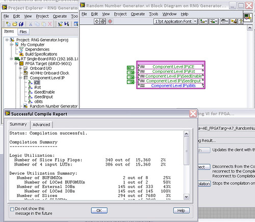
After that the output indicator comes with CLIP, compilation to fail...

NEITHER sbRIO-9601
LabVIEW 8.6.0
LabVIEW FPGA
Windows XP (32-bit, English)
No conflicting background process (not Google desktop, etc.).Usually a "trimming" error gives to think that there are a few missing IP. Often, a CLIP source file is missing or the path specified in the XML file is incorrect.
In your case I believe that there is an error in the XML declaration:
1.0
RandomNumberGenerator
urng_n11213_w36dp_t4_p89.vhd
fifo2.vhd
This indicates LV FPGA to expect a higher level entity called "RandomNumberGenerator" defined in one of two VHDL files. However, I couldn't see this entity in one of two files. If urng_n11213_w36dp_t4_p89 is the top-level entity, edit the XML to instead set the HDLName tag as follows:
urng_n11213_w36dp_t4_p89 Also - in your XML, you set the 'oBits' music VIDEO for output as a U32, however the VHDL port is defined as a vector of bits 89:
oBits: out std_logic_vector (89-1 downto 0)
These definitions must match and the maximum size of the vector CLIP IO is 32, so you have to break your oBits in three exits U32 output. I have added the ports and changed your logic of assignment as follows:
oBits1(31 downto 0)<= srcs(31="" downto="">
oBits2(31 downto 0)<= srcs(63="" downto="">
oBits3(31 downto 0)<= "0000000"="" &="" srcs(88="" downto="">Both of these changes resulted in a successful compilation.
Note: The only compiler errors when you add the flag because otherwise your CUTTING code is optimized design. If the IP is instantiated in a design, but nothing is connected to its output, it consumes all logic? Most of the time the FPGA compiler is smart enough to get it out.
-
View the maximum and minimum values on the waveform
Hi, I have a table of waveform and want to display the values of maximum and minimum of the graph with the arrow. I tried to change with the property node, but I still haven't expected output. Could someone can help on this?
Attached to the vi.
I ran your VI and it seems to work, but it is difficult to report on its work for several reasons:
1. the default annotation is black, which is difficult to see on black background graphic. Change the color of the annotation or change the color of the graph.
2. scale there was not settled in auto-scaling, so I had to go to access my data, which makes it also difficult to locate annotations
3 If you are using auto scale on the y-axis, the annotations will be always difficult to see because they will be outside the limits of the graphic scale car, I would recommend manually set the scales or by using the offset property label of the sliders to make the label in the view visible
In addition, each time you add two new annotations to the curve, is this desired? If this is not the case, use a constant of cluster of annotation and a cable which, in your package names, then build a table with the poles of two annotation.
Hope this helps,
SoC
Maybe you are looking for
-
Hello:Outlook Express 6 with XP I deleted some emails accumulated in My paper this morning. When I went to O.E.6 to read some old emails, there are NOT, well there are 40 different types of emails were sitting in front of access to my documents. Appa
-
How to eliminate the moved from the screen?
Recently, I installed AVG 2011 download free and removed from the worn Norton Security System. My screen shakes intermittently, especially when I use Word. Also, I recently downloaded some long scenarios.
-
How can I use process explore check PID 1176 60% CPU svchost.exe? Help, please.
As the title, how can I use process Explorer to check PID 1176 60% CPU svchost.exe? Help, please. The task manager has PID 1176-60% CPU, all the time, which I believe is the reason my pc works so slow. How to use Exp Pro to know what is actually usin
-
Long-awaited problem, really need help.
Hi, hope you can help me it's been 3 years in manufacturing and really impact the performance of my window. I have several errors on my computer and can't do some things that I really need to. 1. I can't update my windows and I have not for a long ti
-
Unable to start - start the computer to a distorted screen
original title: unknown problem with repair/recovery, tiles strange system startup screen? Help! Lately, my computer acted up (Dell XPS 410 w / Vista Home Premium so this is important) and when I start the computer and access the boot screen, I get w