NEITHER 9205 digital output configuration with DAQ Assist
Hello
I have two NI 9205 Analog Input Modules which I have configured to read from each of their 32 channels. I used the DAQ Assistant help generate the vi which contains the task out - DAQmx event and also the DAQmx Read vi.
I used the Wizard twice, once for each module 9205 and then put the playback functions in a sequence structure so that only read would be carried out at the same time. It all works very well!
Now, I want to add in the code to wait in a loop before all loop containing playback functions, so that the user can press the GUI to send a logic 1 to the unit under test, and after it is sent immediately starts collecting data.
The DAQ Assistant Help does not recognize the module 9205 when I try to set up a task to write a digital output. 9205 a 1 digital output so why is the wizard does not recognize this? I also tried to create a task manually, but I got stuck.
Someone please help. I can reach the source if needed, but I thought that the descriptions above were sufficient.
Thank you
Gary
Hello
You are right it shows a line in this user manual, and in fact, you have found an instance where an important piece of information was left out of the documentation. This digital output line is actually only available when you use a cRIO chassis. It will not work with the chassis for the acquisition of data compact 9172. Here is a knowledge base that explains it. I'll also go ahead and file a request for corrective measures so that this note be included in the next version of this manual. Thanks for the comments.
Chris
Tags: NI Hardware
Similar Questions
-
9205 digital entry into Compact DAQ sistem
I have a Council NI 9205 and I want to use the digital input to acquire a digital fashion Laser diffuse sensor signal, to measure the speed of rotation of an electric motor. The problem is that I have not access to PFI0 in terminal mode of spring. NOR Max I can only receive analog signals. Thank you!
Hi Padeanu.L,
You are right that it is not possible to use PFI 9205 MAX line using the DAQ Assistant. However, it is possible in any programming environment that you prefer (LabVIEW, C, etc.). The PFI line cannot be used as a digital task, but it can be used with counters (edges of County, period, frequency, etc.). For example, in the Counter - County Edges.vi example, you can set the input terminal/9205DeviceName/PFI0 and the meter/ChassisName/_ctrN, where N is the counter that you want to use. The underscore character counter is because the 9205 has only one PFI line that does not support all modes of counting cDAQ, which is also why he does not for you in MAX.
-
Maximum speed of digital output of the DAQ 6009
Hi all
I'm trying to generate a clock the digital output on my USB DAQ 6009 puse. The maximum frequency, that I was able to produce was 0.5 kHz, but I would like to generate at least 1 kHz. I HT wired port0/$line0 of the OID of data acquisition to the data acquisition ai0 and attempted to read the output via the input of an analog of the same device. I have attached the programs here. Don't know if it's right. You can help. Thanks in advance.
150 s/s is the maximum rate of the analog output. The 48kS/s is the maximum rate of the analog input. Read a little more closely.
This unit will not do what you want. I recommend putting the hand of your representative local of NOR and discuss your needs with them. They should be able to set you up.
-
How to select the signals from the output of a DAQ assistant
Hello!
I am a new user of Labview 8.5 and I work with a USB-6210. I have two different instruments connected to the same USB device, half of the channels are used for the transducers of pressure where I only need reed and record data, while the other half are associated with TCD detectors where I need to perform an analysis of the signal to get and save the data. I'm in the first stage of construction the block diagram, once I have defined each of the signals that its correspondent of channel using the DAQ assistant, I need to select and separate the signals coming from sensors of pressure from those who come by the TCD detectors, before that I can continue to draw the block diagram. I am using the function select Signal, but I don't know how to do this. Can you get it someone please let me know at least in which manual, I can find a good explanation? I have read the getting started and the LabView user manual, but they have not been very helpful so far.
Thank you!
I fixed it. As you say, I had some mistakes in the thread, but it's working now. Thank you very much for your help! It was very useful.
-
Control relay with Boolean switch using DAQ assistant 9481 - problems
Sorry for what may be a stupid question but I'm stuck in quicksand.
I use a relay module 9481 and have two external relays connected lines 0 and 1.
When I create a digital output 0 line by line, I can run the test inside the express and activate the relay and turn off without problem.
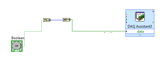
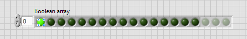
The generated block DAQ expressed expects a Boolean input of 1 d. (See attached photo).
I want to connect a Boolean switch relay line disk 0. You can connect live not because the switch is Boolean and the input is Boolean 1 d - I'm a conversation in the pict.
All plumbing lines display results, the relay never active.
Any bunch would be greatly appreciated! Thank you
Mr._Mechanical,
Welcome to the Forums of switch OR this forum is generally intended for products OR-SWITCH [such as the NI PXI-25xx & NI SCXI-11xx], I think I know the answer to your question.
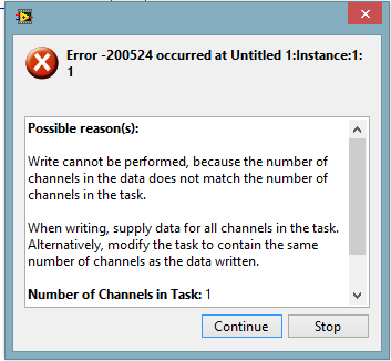
I think the reason why it's a failure is the conversion you make generates a table of 16 Boolean [as the 'boolean to (0,1)' function creates a data I16 type] with your data more false data points 15.
When you try to control the relay, he sees 16 datapoints are you Commander to a single port [channel] and so error out.
My suggestion would be to use normal DAQmx digital output screw [with, he set up as ' Digital > single channel > single sample > Boolean (1 line) "] rather than the DAQ assistant.
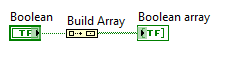
If you use the daq assistant, simply by using the function 'Building the table' will transform your simple Boolean data point in a Boolean array containing a single element.
While the DAQ assistant is very easy to use, I recommend that you use the DAQ assistant, because this reduces the features and increases the execution time.
-
take the digital output USB-6001 always high or low in c
Hi all
I am new to the NI DAQ interface. I have a USB-6001 and I am trying to use this device to control some flowchart in C. What I want to do is:
* set digital output lines with high and low intensity and change their status as needed (in C).
I tested the device NEITHER Max--> Test panels and found that the device is capable to do that. Then I try to do in C. I have checked hace examples and function I use is one called "DAQmxWriteDigitalU32". I have problem in the understanding of its input parameters. I tried something with my own knowledge, but it does not work as I expected. Here is a test I did:
data uInt32 = 1;
Int32 wrote;
TaskHandle taskHandle = 0;
DAQmxErrChk (DAQmxCreateTask("",&taskHandle));
DAQmxErrChk (DAQmxCreateDOChan (taskHandle, "Dev1/port0/line7", "", DAQmx_Val_ChanForAllLines));
DAQmxErrChk (DAQmxStartTask (taskHandle));
DAQmxErrChk (DAQmxWriteDigitalU32(taskHandle,1,1,10.0,DAQmx_Val_GroupByChannel,&data,&written,));taskHandle = 0;
DAQmxErrChk (DAQmxCreateTask("",&taskHandle));
DAQmxErrChk (DAQmxCreateDOChan (taskHandle, "Dev1/port0/$line0", "", DAQmx_Val_ChanForAllLines));
DAQmxErrChk (DAQmxStartTask (taskHandle));
DAQmxErrChk (DAQmxWriteDigitalU32(taskHandle,1,1,10.0,DAQmx_Val_GroupByChannel,&data,&written,));I just want to set ' Dev1/port0/line7' and ' Dev1/port0/$line0"at a high level, but only ' Dev1/port0/$line0' answer me. The second parameter of the DAQmxWriteDigitalU32 function is numSampsPerChan. If I replace (currently 1) with a higher value, such as 100, I see that "Dev1/port0/line7" sends a number of 1 output, then back to 0. So I guess that the problem is just that I understand not all parameters for the DAQmxWriteDigitalU32 function. Is someone can you please tell me how I can set up a line of digital output 1 or 0?
Thank you!
Hongkun
Hello
I finally find a way to do it! The feature works very well, and my problem was not set the data value to write correctly. It seems that if I want to write a 1 to the port0/line1, I put "data = 2 ^ 1" rather than "data = 1", because by default it is the second bit of the port.» Similarly, "data = 2 ^ 7 ' high level to port0/line7. I find that this setting is surprising when you want to control an individual line. It seems more reasonable when you control the whole port. In any case, is to solve the problem!
Thanks anyway!
Hongkun
-
module relay and DAQ Assistant
Hello world!
I am a beginner, and currently dealing with simple business priori Labview. Recently I got a USB relay Module must be integrated into an alarm system. Let's say that if we get some more value than the other, the relay must be closed and activate a siren (see attached example). For this I used the DAQ assistant and set up one of the output channel of the module. Using a simple Boolean switch, I can easily open the relay and close. However, if I use a case structure, an error is obtained, as the DAQ Assistant for an outing can be only used once. I mean, if the relay is closed and I want to go back to the initial situation, i.e. open relays, what should I do?
Schematically:
-If A > B, then closed relay
-If has
Sorry for the explanation of disorder, but I think you get the point.
Thanks in advance
I just got. The problem was that in the main vi, not in the example that I have attached, the same output via the DAQ Assistant has been configured for two structures of different cases. Obviously the relay module was going completely crazy, since I had two independent pairs of TRUE and FALSE labor at the same time. If I get, for example, TRUE for one structure box and FALSE for the other, the switch knows not what to do. I hope it is clear now...

-
DAQ Assistant as a selector of case
Hello
I'm reading an entry to my daq assistant digital camera, and then to hold for x number of seconds, up to that time. The entrance to the wizard matter not after the first entry.
So, I used a switch case and started trying with a virtual switch. Everything worked fine... until I begin to try with the daq assistant. The output of a data acquisition assistant is a table 1 d of boolean. The entry for the case selector is a Boolean value.
It is possible to select the cases according to the output of the daq assistant? If it is true, how can I do this?
Greetz Margaret
I added a table of index to your code that modifies the array to a single digit. Remember that this only gives you the first digital input. If you switch to a different channel, you'll have at this table to a different number of the index.
Second time isn't a very good way to measure time so I changes the way vi a measure of time.
Thirdly, the outside while loop is not necessary. The two loops will be run until you press the stop button. I think about the use of an event to capture the stop function so that you don't need to a stop button.
-
digital output remain on inout end is off
Hello
I've been rattleing my head on this for the last two days with no luck.
What I try to do is the following:
Send a signal in a NI9421 Module, when the module receives this signal, it should exit on the NI 9472. These 2 steps I've completed and work however is the next part whicc I have problems with.
When the input signal is removed from NI9421 I would kepp receives a signal from the NI9472 for a period which can be easily adjusted.
I tried to highlight delays / waits (FOR loops behave as counters), while loops etc, but this doesis delays the time between entry Street to before the output turns on. for example. If I put in a 5 second delay, entry must be closed 5 seconds before the output turns on, and output will then stay on for another 5 dry.
Any help is very appreciated.
Thank you
John
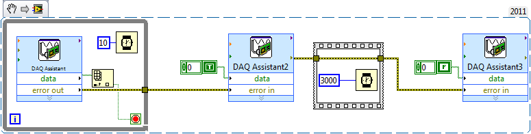
Hi John,.
Take a look at the sample code below along with a description, if all goes well it will help you get started.
The while loop in the early polls pin digital input and a real wait to exit the loop and enter Assistant2 DAQ. The while loop in it has a wait of 10ms. This is to avoid it running fast and hogging all you time CPU. Since the output of the DAQ Assistant, in the while loop is a table, table VI Index allows to get a value that is wired in the loop condition.
The yellow lines used throughout of are lines of error and these can be very useful in LabVIEW to synchronize / order parts of your code. Following the order of the execution rule of in that the DAQ Assistant2 will not begin until all loop has finished running.
I then used a flat sequence order within 3 seconds (with error lines) between the second DAQ Assistant and the third that turns off the digital output.
Hope this is clear and useful
-
DAQ Assistant as input for the formula
I need the output to my DAQ assistant for that entry into a knot of formula. But I can't do it because the terminals are different; data Dynamics vs double [64-bit real (precision ~ 15 digits)]. Is there a way in which I can use these dynamic data in a node form?
Look in the express palette under the manipulation of signal for an another express VI, called "DDT".
-
Hello
Here's my problem: I want to generate digital samples (10-bit) whenever I get a digital external trigger.
This should be easy since I could still do it with the express DAQmxVI.
But the switch can go up to 120 Hz and 16Hz, the generation is not fast enough. It seems like the writing of digital output configuration takes too much time on each loop.
I don't know I'm missing something... can anyone help me on this or point me to some documents that I could use?
Which would be very appreciated.
Thank you
R
PS: I use a NI6351 USB card to get the external trigger on PFI0 and write the numeric data I want to send.
I found the answer and share the link here:
https://decibel.NI.com/content/docs/doc-25189
Thanks to Nathan-P!
Basically my USB6351 NOR is not redeclenchables, otherwise, you just add a property trigger Daqmx with redeclenchables true node. But with this thing, it works great!
R
-
DAQ Assistant does not give me any options trigger
Once I have configured my DAQ Assistant for acquisition of data and the channel my card, I double click the assistnat and go to the menu of trigger to set the trigger but all the options are greyed out. I use an NI 9215 data acquisition card.
winterfresh11 wrote:
Once I have configured my DAQ Assistant for acquisition of data and the channel my card, I double click the assistnat and go to the menu of trigger to set the trigger but all the options are greyed out. I use an NI 9215 data acquisition card.
That does not surprise me. There is no way to trigger these devices. You are sampling whether or not
-
digital output without DAQ Assistant
Hello
I can produce a digital output signal of some sampling rate 10 kHz with the acquisition of data-assist. Now I would like to implement the same functionality with normal DAQ - screw, as I have to synchronize serveral exits lateron. However, I failed get the normal screws so that they work as the DAQ assistant. The most important thing is out the arbitrary signal with 10 kHz.
Thank you.
Thank you very much. The idea of watching inside the acquisition of data-assist helped.
-
How to change the input range (DAQ assistant) with a digital command?
Hello everyone
I am currently working with the NI USB-6218 acquisition card.
In order to acquire a signal, I would like to be able to choose the input range of the DAQ with a digital command Wizard (and not opening the window of DAQ assistant) (as 'number of sample' and section 'rate'...)
Is this possible and if so, how?
Thank you very much in advance for your answers!
You can't with the DAQ Assistant so just click on and select "generate the Code of OR-DAQmx. You can edit the Subvi who performs the installation.
-
I have a DAQ Assistant configured to read 2 channels at the same time. When I have a graphical indicator of wire to the output, I see 2 signals mixed together. How I divided them into separate signals?
When I wire any type of indicator, it is show that a release of a single channel.
I want 2 indicators showing 2 different signals as expected from 2 channels configured. How to do this?
I tried to use split signal but it end by showing that 1 out of 1 signal two indicators.
Thanks in advance.
Yes you are right. I tried, but I don't have the result.
I just find the path. When we launch the split signal, we should expand it (split signal icon) by top, not the bottom. It took me a while to understand this.
Thank you

Maybe you are looking for
-
Laptop bought in 2014, but barely used until recently. Trouble with apps from freezing. Duty to force quit mail, preview, browser, etc and restart several times a day. Ran disk utility and no problems have been reported there. Don't know what other d
-
It has Geforce 550 GTZ can hold inside my HP Pavilion p6720f
Hey guys, just wondering if anyone knows if the Nvidia gtx 550 ti fit in this http://support.hp.com/us-en/document/c02628244 which is a link to the PC http://www.GeForce.com/hardware/desktop-GPUs/GeForce-GTX-550ti/specifications this is a link to the
-
Gets message "install updates" every time I stop the Windowes XP Professional computer.
Original title: I keep getting update requests. For the last 2 days I have been doing the updates 'install' everytime I close to the bottom of my Windows XP pro. It is not usual for my PC. Why does This, and what should I do?
-
I get a blue error screen pretty frequently. I took down the details of the error several times and it seems to differ slightly each time. I used this website http://aumha.org/a/stop.htm and used step 1 in the general troubleshooting of STOP Messages
-
MS Paint build upwards: not enough memory or resources to complete the operation
I call this iguana impressive in the painting and I wanted to color. I decided to go for a black and white look and configured settings and chose the black and white, to give me the white instead of color.I zoomed to 300% zoom, white selected as colo