Measurement of acceleration
Dear all
I am a new user of labview
How to measure the acceleration and deceleration of the vehicle?
I ride an accelerometer for the firewall Panel awning in a car, but instead of mesuring the acceleration of the vehicle, the measure of the vibration of the firewall Panel sensor. What is the right method to get the acceleration of the vehicle?
I used for IEPE accelerometer with range g to 500g, 3-18 kHz frequency range.
Please advice
Thank you very much
I worked with accelereometers once, we used an accel and a determinie gyro axis roll of a platform. We used additional filters (a low-pass filter for the accel and a high card for the gyroscope) and the cut-off frequency, that we ended up using was 0.5 Hz.
Good luck.
Tags: NI Software
Similar Questions
-
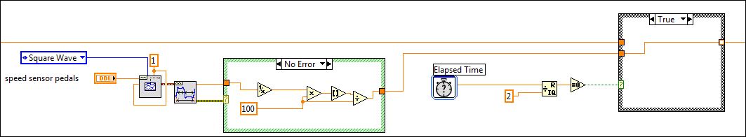
Hi all, I have a question regarding the measurement of acceleration. I have an idea how to do it, but it does not work for me.first of acceleration is all (V1 - V0) / hour. So what I do is the following: I a deal structure and every two seconds, it jumps to true. When this happens, the value of the frequency (from a generator of squares) is transferred to a shift register. After two seconds the case becomes true again and again, this value is read. then these two values should follow the formula I gave. but I can't find a way to 'save' this second value.
hope I get a little bit clear on this...
hope someone can help me, it's probably something small or stupid. but I can't find it... was to look at that for a few hours and try something different, but to no avail.
Thank you very much in advance
Oke, I found the solution. I'll post my VI here so if other people might need.
-
To input analog shutdown when the analog output is completed and synchronization
Hello
I'm trying to get my LabVIEW program to send analog output to a computer and read acceleration using the cDAQ-9184. Chassis output that I use is the NI 9263 and the chassis of entry is the NI 9234. I generate a signal of white noise using LabVIEW Express signal generator.
The first problem I have is the synchronization. I had an old VI that has begun to measure the acceleration just about a second after the entry has been given to the machine. I used the LabVIEW tutorial on how to sync the analog input and output, only to discover that it does not work with two different hunts. Then I found another tutorial that shows how to synchronize different frames between them.
The second problem is the cessation of the LabVIEW program. What I want to do is to generate the signal and then simultaneously send and read the input and output analog, respectively. It is because I don't want a phase difference or any shorter signal for a direct comparison. But as soon as the signal is sent to the machine, I want the entry to stop analog playback and then then the LabVIEW program must stop. I want to be able to choose any length of signal to be generated and stop as soon as the entire duration of the signal has been sent to the machine.
I tried 'DAQmx stop', "DAQmx Timer" and 'DAQmx's task made?' and none of them have worked for me. It is also my first time on a forum posting, so I hope I gave enough information. I enclose my VI as well. The VI shows I read an entry for the analog input voltage, but I am only using this to try to get to the work programme.
I'd appreciate any help I could get.
Thanks in advance
Peter
Hi Peter,.
I have some recommendations for you that I think you will get closer to your solution. First of all, I assumed you meant that you had 1 chassis (cDAQ-9184) who had two modules in it (NOR-9263 and NOR-9234). My next steps are based on this assumption, so if it's wrong, please let me know.
For your first question about the synchronization, the code you provided is very close to what you need. You need to do, however, implement architecture master/slave for startup tasks DAQmx functions. To do this, you can add another frame to the flat sequence structure and put the master start task (input voltage) after the start slave (output voltage) task.
To manage your second question and that the program ends at the point where you, the first step is to get rid of all the logic that you use with the local variable of length of time. Rather than use this logic, just wire the node "task performed?" of "is task performed?" operate to stop the loop. This will cause your loop to stop as soon as the signal is sent to the machine.
I have some other recommendations for you that will increase the performance of your program:
(1) rather than writing on file inside the last loop, you can use the DAQmx Configure Logging (PDM) .vi. You will place this VI between DAQmx Timing.vi and DAQmx Start Task.vi to the task of the analog input voltage.
(2) after the last while loop, you want to stop the task and analog outputs as well with another DAQmx stop Task.vi.
(3) rather than using a local variable for the entrance of displacement and wiring it in the DAQmx Write.vi, you can wire directly from the output waveform of the wave to build function node.
That should help you get started in the synchronization of these tasks.
-Alex C.
Technical sales engineer
National Instruments
-
(3) multiple analog inputs (DAQ) Ai3 is copy Ai1 why?
Hi all
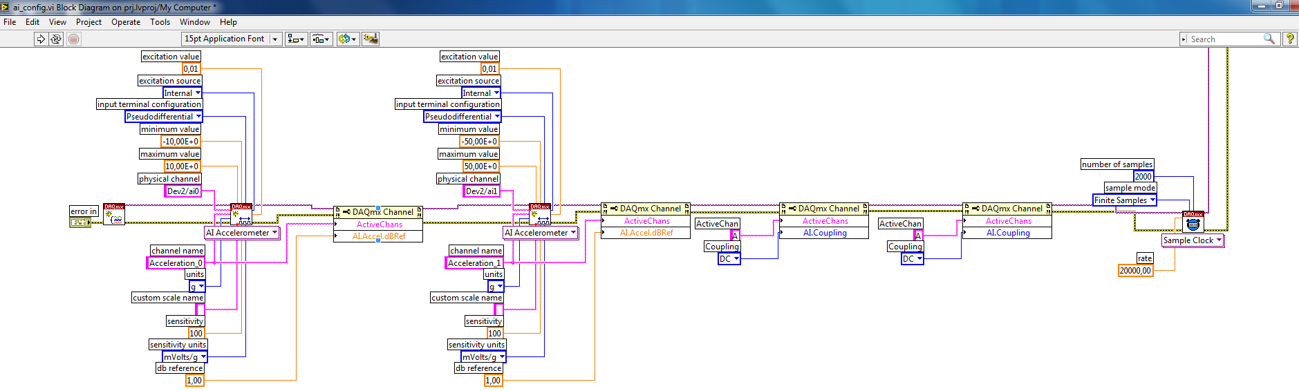
I've been a user of LabVIEW for about 4-5 years, but this is my first post on the forums. I wrote a code that will collect three entries, an acceleration (of the accelereometer) measured in volts, strength (from a counter force) also measured in volts, and a unique tension of a thin piezoelectric film. For simplicities sake you can just think of them as three well under the maximum 10V voltage inputs. Each tension is supplied with Ai1, Ai2 and Ai3 in my DAQmx measurement Board.
The purpose of this code is to study how a 3d printed energetic vibrations harvest table of coated piezoelectric beams performs under different conditions of excitement. (If we shake harder or softer beams at different frequencies, the amount of energy can us our table colelct)
However, I noticed that my piezoelectric measurement is often completely wrong. The measurement of acceleration data are for some reason above coppied and appear in my graphics rather than the correct data of the Piezoelectric sensor! I don't understand why this is happening. If I short circuit Ai1 and Ai2, Ai3 (which has the Piezoelectric sensor) work very well and give me the correct measure. But when I try to measure all three at the same time - it always gives me a wrong result.
I was wondering if someone could take a look at my VI to see if I'm possibly using code collection data incorrectly. Or is there another method to perform the same task that could isolate Ai1, 2 and 3 in a more clear and well-defined way. (but they still need to all get collected at the same time!)
Thank you for all the recommendations you have. My code is attached.
I have not watched your VI because the problem is almost certainly in the material. You probably have "ghosts." Your piezo sensor connected to Ai3 probably has an important source impedance while other sources have much lower impedance. Search the Forums for ghosting for more details.
The best solution is to provide a package of signals (essentially an amplifier with a low output impedance) between your piezo device and the acquisition of input data.
Another possibility, suggested by your comment about shorting Ai1 and Ai2 is to add one or two unused channels between the low impedance inputs and piezo entry. Short entries (in the same way you did Ai1 and Ai2). Read all channels. Throw the data for channels short-circuited. This is how it would look:
Short AI1 accelerometer, Force Ai2, short Ai3 Ai4, Ai5 piezo. Read the Ai1:5 channels. Discard data for Ai3 Ai4. While this may work for prototyping purposes, it may be not a good long term fix.
Lynn
-
Using NI CompactDAQ for helmet safety Crash Test - case study OR
Hi all
I have a question about the counter function in LabVIEW. The example below shows a case study for a test sefaty helmet using CompactDAQ.
http://sine.NI.com/cs/app/doc/p/ID/CS-785
They say:
The helmet is declining, a sensor passes through a barrier of speed, as we use the counter/timer function to measure the speed of helmet just before impact. This triggers the data acquisition system, that measure the acceleration that the head feels upon impact.
My question is: if they used a photoeletric sensor, what is the purpose of using a meter? Why don't you just simulate the relaxation of trigger.vi DAQmx early?
I guess that the counter/timer function is to measure the elapsed time between two positions: there should be two-door sensor? To calculate the speed, you can divide the distance between the two doors with the passage of time.
-
Hello
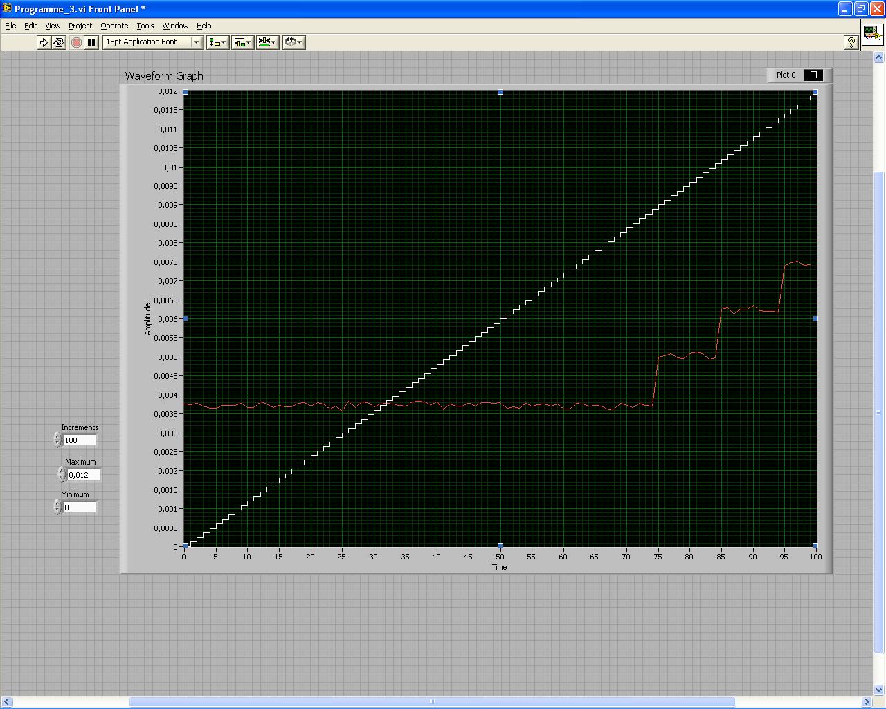
I have been asked to draw the output voltage of the USB-6008 vs the entrance of the NOR-9234. The cards are interconnected, so that the NOR-9234 should read exactly what the USB-6008 case sends to.
But there is a strange phenomenon that happens, the NOR-9234 is unable to read the signal under 3.5mV. I don't know where it comes from, you have some ideas?
This could be the USB-6008, or the NI 9234?
On my graph, the white line is the signal I'm sending to the usb-6008 (ideal signal) and the Red corresponds to the entrance of the NOR-9234.
Thank you
Hi Dibbs,
We look at a few things here - the accuracy of the AO of the 6008, the accuracy of the 9234 AI and the use case of the 9234. The 9234 is a DSA device, so is it is optimized for measurements of acceleration and vibration - not measures of low frequency/DC. The offset of the 9234 error is 7.1 mV and the absolute accuracy of the OD 6008 is 7 mV, up to 34 mV full scale. One thing to do, you can try using the AI of the 6008 to characterize the AO 6008 or use a device optimized for DC, as a DMM measures.
-
USB-4431 offset voltage, how to eliminate
I recently bought a USB-4431 for it's accuracy. The question that apparently the IEPE is enabled by default. That's why he anhile no signal I am measuring. The manual gives a lot of instructions of how to disable (OFF) or change the current of the IEPE, but only during its use in a measurement of acceleration of reduction or other IEPE devices. These option are not there when the device is configured as a simple voltmeter, but still the current lag is still there. Is it possible to disable everything by being simple voltmeter mode?
The manual States that it can be disabled, but instructions applies only to modes that I don't need.
Thank you very much.
Benjamin Couture
Hello
Thank you for your reply, I tried a lot of things and realized that the issue is not the IRBP, there is a lag of gooseberry 8uA on the device that I can not understand how eliminate. I'm starting to wonder if I was just delivered a faulty device. I as well as it could be a calibration problem, but I see no calibration of the input current.
Ben
-
Measure acceleration and temperature simultaneously
Hello
I have problems to make a correct temperature measurement and stable, I think that measures acceleration are correct. I use a PCI 61110 data acquisition and the temperature sensor is a type k thermocouple, I tried to change the thermocouple with a probe, but the result has not changed and I checked the examples to see if I got something wrong in my code but I can't seem to find it. Please could someone help me and the vi is attached below.
Hi Bnzi,
I looked at your code and it seems fine to me, then I would try the simple tests to see if it works.
Try to ensure that you can see your card in Measurement & Automation (MAX).
- Open LabVIEW, got to the 'Help' tab > find examples
- Glance in the middle and open area"input output material & > DAQmx > Analog measures > temperature '
- Then choose an appropriate example (for example sample Thermocouple Acq) and try with your hardware
If it works, then it should refine the question to know if the problem is the code, drivers or your hardware.
I hope this has helped!
Kind regards
-
Desktop PC's processor HP 251 - a11, Windows 10, AMD quad core A6-6310 accelerated with 4 GB memory DDR3 system and 500 GB hard drive. I installed I tunes last version and cannot operate. Error message says Hello not activated. Tells me to go to the Control Panel then administrative tools and allow to Hello. I followed these instructions, but I can't activate Hello. What did wrong and how I can activate the Hello? My email is * any help is greatly appreciated
< email published by host >
For general advice, see troubleshooting problems with iTunes for Windows updates.
The steps described in the second case are a guide to remove everything related to iTunes and then rebuild what is often a good starting point, unless the symptoms indicate a more specific approach.
Review the other boxes and other support documents list to the bottom of the page, in case one of them applies.
More information area has direct links with the current and recent buildings if you have problems to download, must revert to an older version or want to try the version of iTunes for Windows (64-bit-for old video cards) as a workaround for problems with installation or operation, or compatibility with QuickTime software or a third party.
Backups of your library and device should be affected by these measures but there are links to backup and recovery advice there.
TT2
-
NI9232 adapted to the PCB - 356 has 02 sensor of acceleration
Hello
I need to measure accelerations for a Test of 'head-Impact '. My boss has already ordered an acceleration sensor 3 dimensions (but only 2 dimensions required), which can be found here: http://www.synotech.de/produkte_skript/downloads/specs/356A02_specs.pdf .
A Testengineer in my company (im a "student work" it) recommended the acquisition of data NI9232 for data acquisition, but I'm not sure if this is best suited. the +/-30V range is already too, so ill have amplify the signal of the sensor. But it is even possible to connect the sensor (not directly the sensor, but this power supply: http://www.synotech.de/produkte_skript/downloads/manuals/482C05_manual.pdf ) with a bnc connector? Article-he gave me, there were '782000-01', but this version didn't bnc inputs as much as I've seen.
Im sorry if this post is a little confusing because I have little time.
Best regards
Alexander as
With a 6 kHz of band bandwidth nealy all IEPE devive with 20 kHz samplerate and two channels will do the job.
The 30V range isn't the problem, the resolution is still quite high, with about 2% to 5% uncertaincy residual resolution of the sensor 10-bit (8 bits) will do the job. with a range of 60V and the output 10V range input (ok, say you sensor application only uses less 4V... you loose about 4 bits of your ENOBscards)
The part of the slope is the connector

The data sheet is a connector 4 pins 1/4-28. and NI IEPE devices usually have a BNC... If you need an adapter (ask synotech, or your boss has already ordered a
 )
) -
Measure the time in seconds each time run you a VI
Dear people,
I'm trying to measure the speed of a wheel using a magnetic sensor and other settings in the vehicle. What I also need to document in my project is the time elapsed (in seconds) each time that you run the program. Is there a way where you can measure the elapsed time in seconds in labview?
Any sort of suggestions or examples would be useful.
Below is an example of how I wanted my final to watch output file.
Time (sec) | Speed (mph). Acceleration |
0 23 5
1 24 6
2 25 7
Thank you in advance!
Rahul-
Hi iZACHdx,
That's what I was looking for exactly! Thanks for the simple example.
Thank you
Piraux
-
acceleration of bench of suspension travel active
my application is a project of active suspension, I need to measure acceleration and integration of two to get the position of an accelerometer sensor.
I found a lot of codes, it only works in simulation, but it does not work when I connect it on the acceleration sensor.
I know that I should remove a CC of the speed signal lag after the integration, but it is not clear how we do.
I know that there are many types of integration features in Labview. which of them I should use.
My accelerometer is ADXL335
http://www.analog.com/static/imported-files/data_sheets/ADXL335.PDF
Whenever you perform an integration, your result is an arbitrary constant added to what is essentially your starting value. You have acceleration data. If you integrate this, you get the speed, but you will need to add the initial speed to this to get the actual speeds. When you integrate the second time, you get the positions, but you need to add the starting position for this to get real jobs. So the constants you add will depend on your actual starting conditions (do not forget that the calculation was invented by Newton to describe physics
).I usually use Simpon rule for numerical integration, but if you are sensitive to performance, you can use the digital trapezoid rule or rectangle integration. Before you do anything, you should probably read on them. The Wikipedia article gives a good overview, but the chapter 4 of the book online Numerical Recipes will give you a much better appreciation for the subject. Most of these methods of integration is available natively in LabVIEW, so you don't have to write them yourself.
-
Error-200431 occurred at .vi DAQmx Create Channel (I-acceleration-accelerometer)
Hello
I tried to use DAQmx Create Channel to accelerometer and yet it responds with error (see below). When I use max OR to measure the accelerometer (I-acceleration-accelerometer), there is no error, and I see that acceloremeter works.
OR PXI-1042 and I use OR-4462 card to measure vibration vith acceloremeter.
Error-200431 occurred at DAQmx Virtual Channel Create
Possible reasons:
Physical channel selected does not support the type of measure required by the virtual channel you create.
Create a channel to a type of measure that is supported by the physical channel, or select a physical channel that supports the type of measure.
Property: I. MeasType
Requested value:
You can select: sound pressure, voltage: Microphone, accelerometer, Position: Eddy Current proximity probe, Force sensor: IEPE, speed sensor: IEPETask name: _unnamedTask<104>
Hi serdaryilmaz,
I'm not sure why the accelerometer mode does not work, but it works very well in normal mode - it maybe has to do with the accelerometer, you? Whatever it is, if it works with the voltage mode, I am happy that we found a way to make it work. Is this an acceptable work around you?
-
Pouvez PCI-6133 aquire acceleration?
Types of PCI-6133 can include NO acceleration. If I connect did to the PCI-6133, then select the voltage as the type of measure. What dose the acquired signal mean? Is there a relationship between this signal voltage and actual acceleration?
Hi Claire,
The external signal conditioner should just a signal of output voltage. You will then want to create a task of voltage and adjust the signal accordingly. You do not have to power personalized with excitement, because you will not apply the excitement via the 6133. As long as you have a signal conditioner that generates a voltage output, you'll be fine using the 6133.
Best,
-
Acceleration in the frequency domain
Hello
I enclose a vi that I already modified the existing example. I will use this vi to measure pressures (pressure sensor) and acceleration (from an IEPE accelerometer). Each of the two sensors is connected to a housed in a chassis CompactDAQ C Series module connector 4. The pressure sensor measures the pressure of the water flowing in a pipe while the accelerometer will simultaneously measure the vibration of this pipeline caused by the fluctuation of water pressure. In this vi, I am connecting a signal of pressure and acceleration TDMS file and then read the two signals on the cards of distinct waveform. The acceleration signal is written and read in the time domain. I need your help to make change more on this vi to take the acceleration signal and read on a separate table in the field frequency and written also the frequency of the field values in a file of PDM. After this change, the vi is supposed to have three graphics of waveform (pressure, acceleration time-domain and acceleration in the frequency domain and opens two tdms files, one for pressure and acceleration in the time domain and one for acceleration in frequency domain.)
I tried many ways all failed because I'm not very familiar with the measurements of vibrations.
I thank in advance.
Hello
It is important that you should decide if the frequency data you are interested in are constants based on time, or if you need to know how the data of frequency changes over time.
For constant frequency over time, take a look at the Fast Fourier Transform: http://www.ni.com/white-paper/4541/en/
If you need to know how the frequency display, take a look at the analysis of the frequency of the common time: http://www.ni.com/white-paper/3548/en/
Maybe you are looking for
-
Tecra S5: Bios updated - cannot change page in the BIOS
I have improved my Tecra S5 BIOS to version 2.0. But when I enter the BIOS, I can only change properties on the first page PGUP PGDN keys, for change of page does not work for me. Everyone knows the same behavior?
-
Help motherboard D10... PLEASE
I got this motherboard from outside of ebay. I thought he had two 8pin & connector 24 pin for power supply, I now see that the connector next to the main 24pin is a 10pin. I don't have the power supply provided in these systems was ryin to Thermaltak
-
ISE 1.2 IETF attribute box 88-pool not available
With the help of ISE, 1.2 and establishment of a new sequence of Radius Server I am unable to use the IETF Radius 88 (box-pool) attribute because it is not displayed in the IETF Radius dictionary. Is there a reason for this? Most of the other attribu
-
no rows returned after haven't added any new tables
Hi allSELECT a.item_no,b.trx_numberOfitems_table oneb customer_header_tbl,c customer_lines_tblwhere 1 = 1AND b.customer_trx_id = c.customer_trx_idAND a.inventory_item_id = c.inventory_item_idAND a.organization_id = NVL(c.warehouse_id,207)and a.invent
-
HelloI want to add a JS on my site but I have no idea how to do (my coding skills are terrible).Here is a link to the JS: GitHub - @emielberends/loadCSS: a function for the asynchronous loading of CSSIt seems that I must add to the head section of my