Measurment of isolated analog input
Hi all
I use card NI USB-6259. I would like to measaure some voltage 5 V on an electronic device provided with the network. Thus, the risk is accidentally on a ground signal I have L line instead of N (the reasons are common). Because it can destroy the card - there is my question here - is it possible to isolate the card and the device, but also be able to measure analog signals? Maybe some additional devices or more?
Tags: NI Hardware
Similar Questions
-
Frequency measurement of analog input using DAQmx C APIs on SMU-6341 map
Hello
I use Linux DAQmx and attempt to measure the frequency of analog input using the map DAQ SMU-6341.
There is an ANSI-C frequency measurement example:
/ usr/local/natinst/nidaqmx/examples/ansi_c/Analog_In/Measure_Frequency/Cont_Freq-Int_Clk-SCXI1126
However, the call to DAQmxCreateAIFreqVoltageChan results in the following error:
DAQmx error: selected physical channel does not support the type of measure required by the virtual channel you create.
Create a channel to a type of measure that is supported by the physical channel, or select a physical channel that supports the type of measure.
Property: DAQmx_AI_MeasType
Required value: DAQmx_Val_Freq_Voltage
Possible values: DAQmx_Val_Current, DAQmx_Val_Resistance, DAQmx_Val_Strain_Gage, DAQmx_Val_Temp_BuiltInSensor, DAQmx_Val_Temp_RTD, DAQmx_Val_Temp_Thrmstr, DAQmx_Val_Temp_TC, DAQmx_Val_Voltage, DAQmx_Val_Voltage_CustomWithExcitationTask name: _unnamedTask<0>
State code:-200431
DAQmx does support the function of the frequency on the map 6341, or should we use examples of voltage and calculate the frequency manually?
Frequency of HAVE it is a type of channel that has been supported only on the SCXI module name of the example.
You will need to use a voltage input channel and calculate the frequency manually for your device.
-
Hallo,
I use the following system:
- OR PXI-1044 with controller NI PXI-8109
- OR PXI-2564 switch module to turn on the monitor of my test device
- Data acquisition multifunction NI PXI-6259 to measure the signal that responded to the questionnaire jump
The two cards are the same - PXI trigger bus. For both, PXI-2564 and PXI-6259 I use DAQmx to set the reading and writing of the channels.
Now, I want to measure the time between the digital output, my unit turns and the analog input, which measures the response of my system.
I can't do work by myself, please help me!
I thank Ludwig.
Hi Ludwig,.
If you can't give us any VI we have difficulties with to help you.
Because I Donat knowledge how your program is mounted it is not easy to know where you should enter signals.
Here's a question similar to yours:
http://forums.NI.com/T5/LabVIEW/best-way-to-measure-time/TD-p/178704
and 2 external links:
http://www.ehow.com/how_8698983_measure-time-LabVIEW.html
http://objectmix.com/LabVIEW/385152-how-can-i-use-LabVIEW-measure-time-between-analog-pulses.html
-
Analog inputs measures with NI6229 using the DAQmx driver
Hello
I have four different analog inputs connected to ai0 to HW 6220 ai3. I read these values with a single task, all 4 channels assigned to this task. When ai0 reads 7V, I see 0.8 V ai1 too, but I expect to be measured 0V. If I just assign ai1 to the task and measure all 4 channels, then I measured 0V as expected (although ai1 contains 7V, I just don't measure it).
Another comment 'funny', is that if I change the order in which I add channels to the task, measurement errors are different.
However, when measured with a multimeter 4-channel show tensions as expected.
Given that my calling task is can not block, I call the function
DAQmxReadAnalogF64 with timeout = 0 and numSampsPerChan = 1.
Any help is appreciated.
Thank you
Kind regards
Deepa
Deepa,
Thanks for the code snippet.
When you call DAQmxReadAnalogF64 the first time and you set a value of timeout of 0, there is a chance that the acquisition is not yet initialized. This is the expected behavior and should not be a problem. If the timeout error died at the first call, you might ignore it or set a different expiration time for the first call only. In all cases, you should drop the first value and start with the second value.
Jochen
-
Input signal is set to +/-0 .5V when it is connected to an analog input
Hello
I have a difficulty connect an analog source to the analog inputs of my acquisition of data (USB-6215). The analog signal is output operational amplifier through a 10 k resistor. I wore the signal out of the amplifiers is 10V peak, I then move the probe across the 10 k (the analog input terminal) and the signal is clipped to +/-0 .5V. If I reduce the amplitude of the signals of source less than 0, 5V Ridge there is no clipping.
Maybe the analog input range the value +/-0 .5V which is causing this as a form of protection? I don't have a LabView to try to change the input range as I do just the wiring.
Analog source is connected to him HAVE 0 and the ground of the analog source is connected to the GND AI.
Thanks in advance.
J
Joel-
Have you tried to read the data through the data acquisition device? If that's what you try to do, I'm curious about what we read.
If you have measurement and Automation Explorer, go ahead and open a Panel to test for the unit and see what are your tensions.
Let us know how it goes.
-
Several analog inputs seem to change any of the other (details DAQ: 2120 BNC and 6062E)
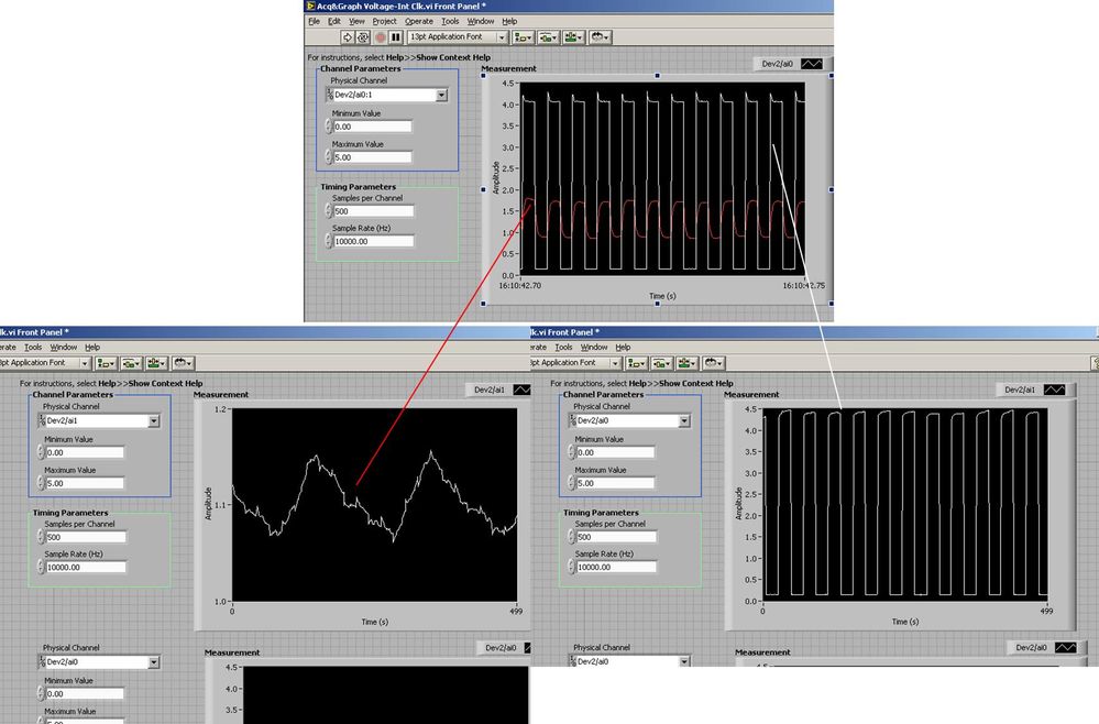
I use the BNC 2120 DAQ board connected to the data acquisition card 6062E to record two analog inputs. An entry is connected to ai0 and the other at ai1. Example vi: "Acq & graph int clk tension" has been used to measure the two entries with the value read NChan NSamp vi (channels being dev2 / ai0:1). The output is the top graph in the image. However, this seemed a bit strange to me that one of them should be modulating with a different frequency. When I record both entered individually (two in low pictures) they are indeed different since the entries shown in the top graph.

Why this would be the case, and how can I overcome this to measure the real signals?
Thank you!
The E series card takes the samples as soon as possible. Thus, for example,.
If you have 16 analog input channels but you only read of
channel 0 and 1, the map will show the channels 0 and 1 right
After and then wait 14 'ticks '. What's that little run-in
the origin of the afterglow.
I think you can get the card to wait a certain
number of ticks with a property node. I have attached a screenshot. You
can find the property node in the palette of functions >
Measurement of e/s > NOR-DAQmx > node Timing. Expand it
Property node so there's two entrances. The properties are in
Left click on the node and going more > converted >
Its properties delay units and sampling clock delay and delay that
you want.If the phase is important so the above is not the best
the option because it causes a delay in phase. So, if you need true simultaneous
sampling, then you will need different hardware. The S series is everything
simultaneous sampling.Or, rather than the Delay property and delay units, try the Rate property
find more > converted > rate.If this is not
work either, you can move the second signal source to, say, AI8 and
Connect everyone to the ground. Readings for these, but just do not take into account
the data. In this way the ADC will sag to the ground at the time where that can happen
the second string in the way so that you should not see this frequency
ghosting on the other channel. -
Problem with a precision of analog input on PCI-6111
Hello
I'm reading an analogue signal which varies from 0-11 V using a card of acquisition data PCI-6111. The signal comes from a Tube set (PMT) which is part of a microscope configuration, so it is very important that the resolution of the analog input signal be as wide as possible generate quality images. According to the data sheet for the PCI-6111, the analog input resolution is 12 bits, which should correspond to a sensitivity of ~2.686 mV for my voltage range.
To test this, I set up a task to analog input with a 0-11 V voltage range to read samples of an analog output, which I wrote a simple waveform. Since the 16-bit analog output resolution that I assumed that it would not limit the accuracy of this measurement. I have attached the VI I used for this measurement below. The analog input data are saved not truncated in a text file.
Analyzing these data, I found that the real input sensitivity is ~9.766 mV, corresponding to levels of voltage exactly 1126,4 and ~ 10 bits.
Is there a reason why the resolution of analog input is much lower that it is indicated on the card? What are some of the ways I could improve the sensitivity of this measure?
Best,
Keith
Sorry, when you mentioned the specs, I thought you already had them. If this did not come with your Board of Directors?
-
reading of the analog inputs with RPC
Hello
Because LabVIEW can not handle this (in VI; the value that you have saved the excel file has not been the same, that I saw during the measurement...) This confused me for a long time
 ), I want to write a C++ program (IDE: Dev - C++) which can read & record 2 analog inputs of the NI USB-6009 box. For this, I looked for an example of National Instruments and I found a little. But my problem is that I can't even use any example, because it has always held a mistake, after that I have compiled and started.
The error once the task has been created and has the :-200220 error number with the description "device identifier is invalid. But I do think that its invalid, because it's the xP example
I must say that I am new in programming C++, which means I could have a rookie mistake. And I couldn't find documentation or something for the NOR-DAQmx library.
Someone has similar problems with DAQmx and C++ and know how to fix? I don't really know what I can do now without a working example or documentations...
Hi Mario
It's the same thing. You didn't just save all of the data:
Please take a look at my comments in the attached VI.
Christian
-
Hello
The data entry in LabVIEW by my USB-1208LS is accurate, but the analog input voltage values are quantified (there are only a few repeating values: 0,691 0.696 0,701 0.696 0,701 0,691 0,691 0,691, etc..). I am able the tensions of four photocells, propelled by the + 5V of USB-1208LS. Each cell is measured in a different channel using the differential input mode. Is it possible to fix the quantification of data?
I don't know if it's a problem of LabVIEW, but attached is my diagram, in the cases where I'm not seized the tension properly.
Thank you in advance.
On the input range, the resolution of this device is about 5 +/-10 V mV, which is exactly what you see. The resolution is established by calculating the length of the total voltage range (20 V) and dividing by the number of steps or bins the A/D converter on this beach (2 ^ 12 = 4096). Yes, resolution = 20/4096 = 4.883 mV.
To get the best resolution, you will need to use a smaller range (if your signal wil fits into a smaller range) or get a DAQ hardware with a higher resolution, for example a 16-bit converter, or 24-bit.
Lynn
-
PXI-6071e offset drift on the analog inputs
Hi, I have three cards PXI-6071E, sitting in a PXI-1042 chassis that is controlled by a computer with windows XP. The 6071Es are connected to the SCB-100 break out boxes that are wired to a pannel of BNC female Panel Mount on twisted pair.
I noticed that all of my analog inputs will drift around-10 V to + 10 V if they are not connected to what whether forcing them to a certain tension. This has always happened. We also see a bit of crosstalk between channels. For example if I open a panel of test in the measurement and automation Explorer I can watch the voltage read on the drift tickets through their full range, and alteration of the signals on nearby channels will appear on the channel, I am able.
Is this just standard behavior and to predict? Is there something more I could do to minimize this drift and crosstalk? I am trying to reduce noise in my system so I figure optimize my DAQ could not hurt.
Thank you
With nothing plugged into the catch to high impedance, drifting you see is quite normal. The front end of the circuitry builds up a charge, crosstalk is proabably due to the multiplexer input (did not check but I think that the 6071 has a) transferring the load to the other channels when they are analyzed.
Search the Forum of ghosting, you will find related discussions.
-AK2DM
-
Analog input problems using PXI-6232
I tried to solve this problem for a while now without a bit of luck. Solution suggestions are welcome.
I use a PXI-6232 with LabView 8.5.1 to accept signals analog several of my sensors. Based on the signals as a PWM signal is generated and the output using PXI-6713.
Some of the analog input signals have spikes in them, which occur at all times during the tests. I watched the same signals on an oscilloscope - without crampons. I change my hardware configuration, and the spikes still occur in the same places. It seems that the program makes some resets resulting in measurement errors.
I have attached the VI and a JPEG of measured inputs.
Thanks in advance
Concerning
Vadim
I was first confused of your time scale
 but it seems that these spices occur every 20ms (not s) what to a line 50 Hz noise due to switching power converters (or a diode without compensation bridges
  )
)Another clue was the measure of the scope. While using the application scope, you opened a groundloop so the spikes because of the dI/DT through the groundloop are another way to get around.
So I'm pretty sure this isn't data acquisition (in this case) this is your configuration.
Provide a cleaning (low R AND L low) path of power (keep them close and twist slightly if possible), add a filter to down the dI/dt, identify the ground loops. (Use your scope with a little as a sensor at the entrance to reel and catch magnetic fields can open eyes)
THEN to clean the last ears (on the acquisition of data) to get the last ppm use selfs
-
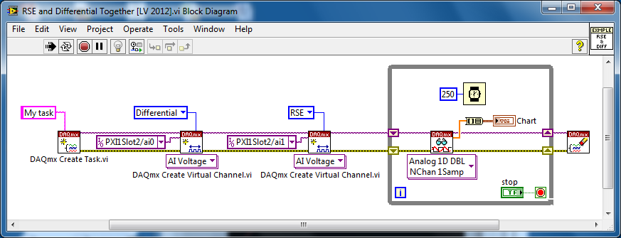
Several analog inputs with different configuration differential/CSR
Hello
Can anyone tell how to measure two analog inputs with different configurations using a USB-6009?
I am aware of the syntax for create virtual channels for the channels DAQmx create virtual so I created two strings using Dev3 / ai0:1 but I would like the first string of the CSR and the second to be differential.
So far I have found no way to specify the configuration of the separate channels.Any ideas much appreciated!
Jack
JackT wrote:
I prefer to use the 'low' level vi is therefore always curious to know if there is a way to set the configuration using the their.
It should be like this:
-
NI USB - 6212 BNC analog input impedance matching
I just ordered a case NOR USB - 6212 BNC DAQ (should be delivered soon). I want to use to measure HV signals using a probe of high voltage of 1/1000 I have.
Now, datasheet of the probe (not a lot of info) says it has an impedance imput 100MOhm. I suppose that it consists of a simple resisitve divider, and if the ratio is 1/1000, I wait so to have a 99.9MOhm resistance in series with a 0.1MOhm resistance. However, the data sheet also specify that the probe is designed to be connected to an oscilloscope with an impedance of 1MOhm. As this input impedance is very low compared to the low value of the separator of resistance resistance, so I guess that the real resistance at the level of the sensor values 99.9MOhm and 0.11MOhm (to obtain the 0.99 and 0.1MOhm when it is connected to the oscilloscope for 1mW).
Therefore, given that the impedance of the USB-6212 according to the datasheet, the analog input is > 10GOhm, I expect to measure higher to true alternative voltages when connected to the acquisition of data from 10%. This assumption has a meaning?
What would be the best way to get around this? Do a calibration and correct the values acquired in LabVIEW code? Or should I add precision 1MOhm resistance at the same time to the acquisition of input data to decrease its resistance to entry to the value expected by the probe?
Thanks for your help!
Since you have a range of 1000: 1 I guess you also need bandwidth (I have a TEK 6015 A
 ), so you need based on the impedance input, a complex value, means he must not only watch but also the ability to input resistance (1 M). demarcation of the field probes have usually some elements of toppings to match the probe and the input scope. RTFM of the help of the probe
BUT a more serious point is that with your probe, you have a very high resistance. And if you look in the specification of the 6212 you will find on page 2 by mistake ppm in logarithmic scale graph! and even 100 k source impedance it not shown.
So I'm afraid that a simple 1 M on the DAQ entry can work if you're only measuring DC, and only if you use a channel on the acquisition of data. A workaround is an amplifier separate buffer with an impedance of good entry corresponding to the specification of your probe and a low output impedance.
-
Medium-sized dynamic data analog input read DAQmx read
Hi, I'm new to labview. Is there an easy way to index using the dynamics of data returned by a readout DAQmx x samples to calculate a moving average? My thought was to read the analog input for X samples pump with the data in another loop through the data, but I can't quite understand how index using the returned data set to extract the measurement value double returned for each sample.
Any ideas on that?
Thank you...
If you get a type of waveform data, why did you ask on dynamic data? No, of course not would you use the conversion of dynamic data on a waveform.
If you want only one channel, then your DAQmx Read could be changed to 1Chan NSamp. If your channel list only has one channel, you will get a table 1 d with a single element that can be indexed. To get the average of a waveform use the statistical function with the waveform. You use the average Point by Point, and not the average function that has a table for an entry.
Make sure you always have context-sensitive help on. You can avoid many of these rookie mistakes simple.
-
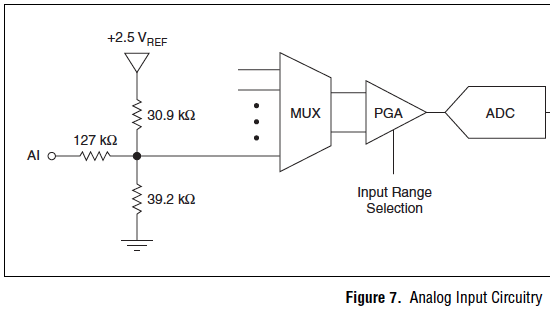
Issues of analog input DAQ-6008, voltage not zero to pin when you are offline
I use the 6008 NOR-DAQ to produce a series of tensions and then read a sense resistor using the analog input (CSR). I noticed that my analog input gives me 1.3 V, when I probe it (compared to the mass of the device), when it is completely disconnected. This changes the reading to give me a different measure of sense than expected resistance.
Why is my pin for analog input non-zero? Any help would be appreciated. Thank you!
The 1.3 V is expected. The USB-6008-and-6009 case have the strangest input of the world circuit. The input impedance is approximately 144000 ohms terminated in 1.4 V. check the document User Guide and specifications.
Lynn

Maybe you are looking for
-
Hi all I need help to convert a file in VI 9.0 to 8.6 VI. Could someone help me please. The files are attached. Thank you very much!
-
audio player on windows XP Pro THAT has been disabled. How to activate?
audio driver Windows xp pro has been disabled. How to activate?
-
Turned off my computer during a factory restore
I have an Acer Aspire One 532 h-2588. I was restore to factory condition when I accidentally turned off. Now, it will not be open. I tried to re - restore it, but it does not work.
-
Hello, I am new to Labview. I need to build a 1 d array of 10 items. I have a digital control to insert items to the table. Every time that, if I change a digital command value, element should be inserted in table. I would do it with registers at off
-
I am trying to open Windows Defender (I have Windows Vista). I get an error message: 0 x 80070424. When I try to download a new version, I can't. I get the message "Vista already has this program. I'm trying to fix the slow performance of my comp