Multi-channel DAQmx - output function generator
Never mind... I got it running by connecting a constant Boolean true to reset the signal of the Signal to simulate vi. Thanks for your help
Tags: NI Hardware
Similar Questions
-
Programmatically, create a multi-channel DaqMX task
Is there a way to create a task of multichannel DaqMX programmatically, without having a task to copy?
Yes and it is an easy way to find a way to do it.
Start by creating a task in MAX (Ben, but I want to avod MAX!) Don't be afraid that it's just a one time event that will allow us to know what are the steps)
Go to a block diagram and steady decline DAQmx task on the diagram and choose the task you created in MAX.
Right click and select 'create configuration and example '. LV will create the code that goes with the taks.
Study the config VI that was created. It will show you what it takes to create a task without MAX.
I hope that helps!
Ben
-
How to control two channels of simultaneous functions AFG 3200 B generator?
The AFD 3200 B function generator has two channels. I want to use both channels generations some vague simultaneous sin. I downloaded the labview driver: Tektronix AFG 3000 Series.
I did three things:
(1) try to connect to two channels in VI.
However, all the screws of example do not support the connection of the name of two channels simultaneously.
(2) run only two signals generating VI with another name for channel at the same time.
However, a single channel runs after the other.
Do you have any suggestions?
Thank you!
Wu Yue
Hey Wu,.
You need two sine waves to be completely synchronized (aka having the same exact phase)?
If they must be synchronized, then the AFG should on the two output channels at the same time, but you will probably need to configure serial in your program.
If they do not need to be synchronized, then is there a reason why you would not be able to simply divided between the output signal two BNC? If this isn't an option, then you will probably need to make some kind of trigger to get both channels to start at the same time.
Lars L
-
Digital output frequency seems to be twice the frequency generated by the basic function generator
Hi Labview forum,
I wrote a program (attached) Labview to generate 3 PWM, square wave, signals that has the same frequency and phase delay right (so that when a signal is off, the other signal is lit. Then the next signal). Everything seems to work fine except that the frequency of the PWM signals generated seems twice as the frequency given to the basic function generator. Anyone have any idea why this is happening? Anyhelp would be greatly appreciated.
Thank you!
Totally agree with the advice of all GerdW than the hardware timing of your hardware DAQ will be much more reliable. That said, part of what you are probably hitting is a little quirk of the primitive delay msec. Requests for 1 msec have long been particularly little reliable (although they * seem * to have improved in recent years, probably due to the better OS support in Win 7 or something).
I did minimal mods to your code with comments from you switch to a timed loop. My quick test showed he is good enough to hit the 1 length of loop of target msec.
-Kevin P
-
Continuity of the functions of the basic function generator and the right time
I need to create a sine wave, point by point, which will be forwarded to the MIP and finally to a channel of analog output on a PCI-6014
Ive tried a few different ways to do it, but everyone has some problems with her slider.
with the 'generator.vi of the base feature.
and also the "sine waveform.vi.
There seems to be problems with this lack of points.
someone helpfully pointed, its very likely windows interrupts the origin of the problem
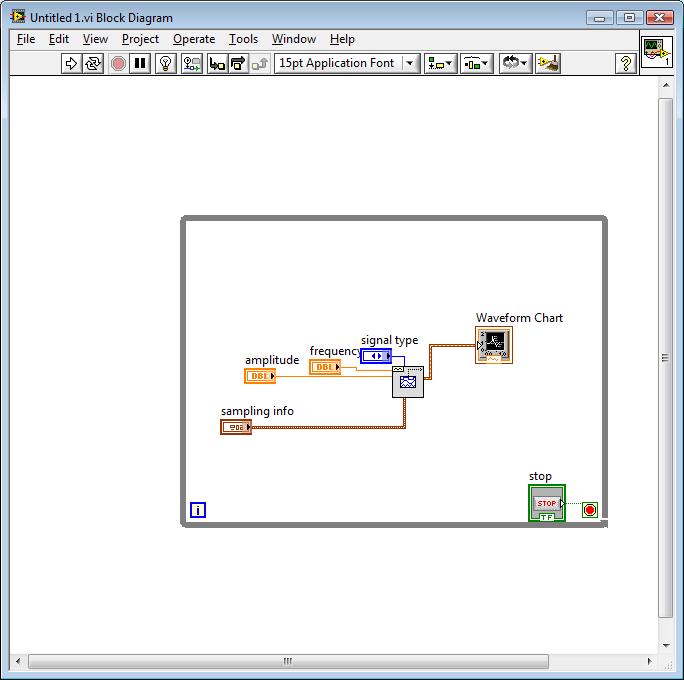
Here is a schematic representation of the panels front and rear
the back panel
the façade has a few points that are missing
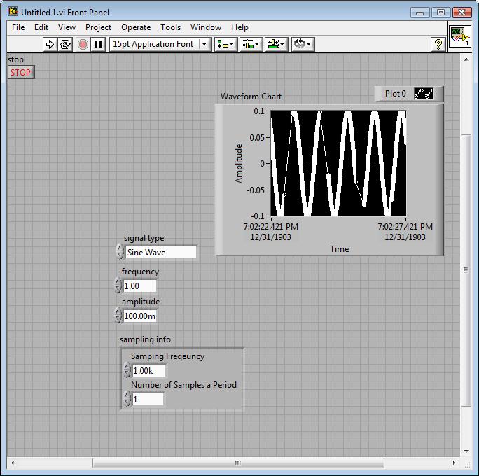
Another way to do that seems to work better known that the signal "simulate" express vi.
It's great because it's actually a way of sine 1htz occur at 1htz.
There are also all the points.
The problem is that as soon as I put in my request, she grinds to stop.
Program speed about changes 10khtz less than 1htz when the basic function generator is replaced with this express vi.
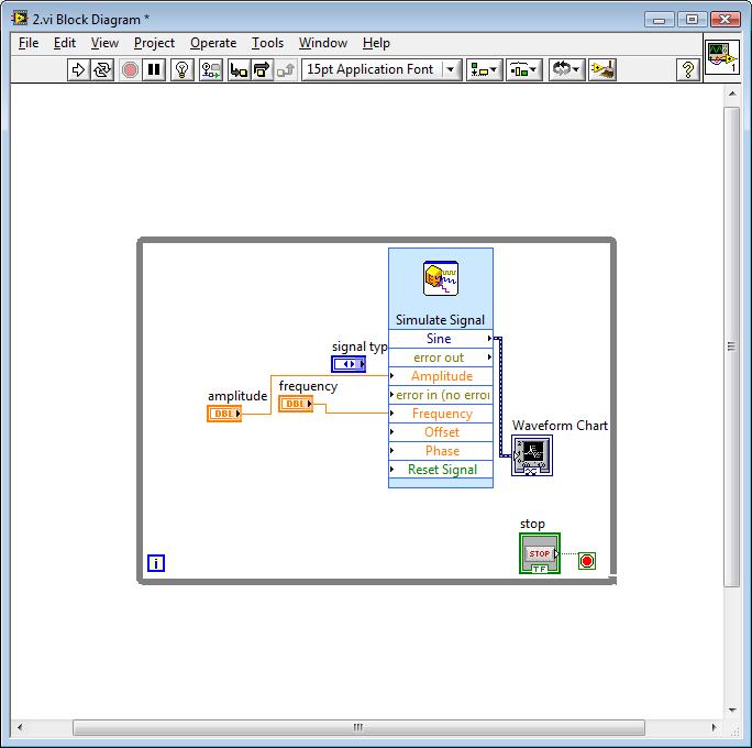
A third idea or concept that has been proposed is to put a programmer to slow the timetable.
It is once again, works fine, no more points are missed in the plot.
Yet, he kills again the speed of execution of the program as everything can wait 1ms (or the recripocal of sampling points interval time).
Someone at - it an idea on how I can get a sine wave in PID, then, in the analog waveform without a huge amount of the efficiency of the program. Im sure this is simple.
Nevermind
accedanta do the 2nd option from the top.
go just to increase the number of samples for now leave the rest of the fastest of the program
-
How can I autoindex looping for to create several channels daqmx
I'm trying to autoindex create a loop FOR containing the DAQmx vi to create AI multi-channel voltage with identical settings, except that I need to apply specific channel names using a constant and specific physical channels using a constant of channel. Wiring of a constant DAQmx of physical channel does not work because the data type is incorrect. Similarly, I don't understand how to use a string constant to autoindex through the channel names is or how to configure the constant string (s) to assign names. Also, when I try to make one of these, I get a tunnel to exit the DAQmx autoindex create channel, rather than a task out. I can achieve my goal using several explicit DAQmx create calls to channel, but for high channel count, it is very time consuming.
I use LV 8.5.
I'm hoping to find the code showing how to perform the conversion type, flattening, or what to do.
Diane has.
I have an array of clusters. Each element of this array is a cluster. The cluster consists of a (scalar) string and input/output (also scalar).
In addition, my TI attachment extracted. I think that your file has been LV2009. If so, you can drag the image from the browser and drop it onto a diagram.
-
How can I get multi channel audio via the HDMI port on an early 2015 MacBook Pro?
I try to get the 7.1 audio channels to flow from my MacBook Pro to a cinema set up. The display works fine now I plug the HDMI in however the sound still Mac speakers. I checked the settings and no HDMI output is available. An airtime option is available, but that returns only two channels as a maximum to the receiver. When I go to the configuration of the source on the receiver it receives video at 1080 p 60herts however it is specifically stated No Audio from the Source.
Also, I have connected my iPhone 6 s more using an Apple through the same HDMI cable adapter and it works perfectly. We also use HDMI with our PS4 occasionally and it works perfectly, even with the 3D.
Thus, the MacBook Pro is early 2015 with an i5, the receiver is a Harmon Kardon AVR 2700 (we run 7.1 channels of this) and we are connecting via the HDMI port through a 50 ft HDMI before. The receiver sends the audio to a projector with 1080 p 60 hertz if it changes anything...
Also if it helps the receiver supports dts - hd master audio decoding, Dolby True HD/Digital Plus decoding, HDMI 1.4 (HDMI is compatible 2.0), as well as multi-channel input and PCM and linear PCM.
I use a "Behringer UCA202' audio device I bought on amazon.com for only $29.
It works very well for the audio 5.1 or 7.2. Works connect optical toslink. Just plug it into a usb port on your Mac and a cable optical toslink to your AV receiver.
My Yahmaha 7.2 audio/video receiver is measuring process the digital signal in THX, DTS, Dolby digital Pro logic, a cinema, etc.

-
Cannot create the multi channels Tx two USRP-2943Rs Session with driver
I have problems of implementation of several USRP-2943R devices in tranmist both of their channels at once. Right now my configuration is a configuration of four chains composed of two devices of RIO. I am only able to transmit at the same time successfully CH0 and CH1. I'm creating a session using two devices and my aim is to perform Tx on CH0 via CH3. In addition, my goal is to use the LabVIEW driver without any synchronization, because I test fix synchronization through post-processing and you want the VI be as simple as possible without the hassle of FPGA programming. I realize has the Simple models OR - USRP Streaming Sync in LabVIEW, but additional synchronization and FPGA programming is too much for such a simple project like mine which would require no synchronization USRP.
My VI and some screenshots of the error messages resulting is attached. I am able to succesfully implement multi-channel Rx deals and attached is my multichannel Rx VI. My question is why I can open and operate a session of Rx mult-channel without problem, while a multi-channel Tx session will give me errors?
My final goal is to merge my multichannel work Rx VI with a mult-channel Tx VI work for measurements in order to test some synchronization post-processing routines that are performed in Matlab.
I think that I found a solution to my problem. I thought to post it here to help others. It is important to use some sort of device to synchronize several USRPs. However. I found that you must reset the device by setting the node of reset function blocks that open and session Rx or Tx. "" If it is not defined, then the ' niUSRP Signal.vi configure
the ID of the specified attribute is not valid for the scope specified (or channel). " error occurs, any circuits that you define. After the node Reset true and place an empty string for my channels Enabled, all was fine. Also, a full duplex system you will be only to first log of Rx with a reset of the device, followed by the opening of a session of Tx without a reset of the device.One more thing, it is that there seems to be a bug if you feed a Tx process a table whose number of lines does not match the number of channels Tx. This will result in weird errors funny will disappear only after doing a hard reset of the units. So, just something to take note of.
I hope this information will help others and this message can be marked as resolved.
-
Extract single channel DAQmx task
Hello
I created a task DAQmx output, which contains two channels. Is it possible to extract the individual virtual channels of the task to be dealt with by two parallel processes? I tried to bring out the ownership of channels using a task property node, but then I get the error that the channel is not part of an active task (see excerpt)
Could someone advise on a better approach, or how to obtain this feature - if that's possible?
Concerning
Dave
Sorry, that VI does not have much sense. You must use a unique DAQmx writing for both channels and 1 sample mode, simply build an array of signals as shown below.

-
BUG? Out of multi channel analog Flips which channel it sends
I a program that channels acquires 4 analog inputs, 2 analog output channels to send and acquires 2 input channels of the counter (on a separate card)
My problem is that the analog output flips which channel it outputs. I built a table and my waveform desired ao0 at the top of the table build entry, then I drag the table of construction down to make entry as a second entry and I plug my second wave this entry. I noticed strange things on the scope. The program worked correctly, but repeatbly.
The analog output channels the following steps
channel 0 is sent to a level of zero, then for 1 data point a level 5. It comes to trigger a signal generator to the output of a wave of fishing 1 Hz, 1Vpp, 2cyc
1 channel is sent with a square wave to trigger a camera to take a picture for each pulse.
Step 1: Open SLOSHTABLEV4.vi
Step 2: run.
Note: the channel impulse is sent the trigger generator waveform causing the waveform to generate each pulse
the trigger channel ends as high. to 5 volts.
Step 3: Run simpleao.vi and set both channels to zeroStep 4: See Re running SLOSHTABLEV4.vi that flips out what channel it is sent!
There are three forms of production,
the right one
one where the waveform relaxation is camerapulse
one where the waveform trigger is activated from the beginning.The solution was to update the drivers. Ugh!
-
I am able to get a multichannel simultaneous sampling on my acquisition of data (USB-6363) without problem. But what I want to do is make multi-channel acquisition in a single task where sampling requirements are different for each channel. For example, I want I want to acquire a total of 1000 samples on 3 channels in a single task with DAQmx as follows the characteristics of sample:
- AI0: Analog Wfm 1Chan NSamp (998 samples)
- AI1 + ai2: 1 d analog NChan DBL 1Samp (1 + 1 sample/channel)
I know I could do just a regular multiple sampling multi-channel acquisition through all three channels then average down from channels 1 + 2, but I don't have that several samples to spare. AI0 is a bandwidth hog in my application and consumes all the samples of data acquisition (2. MECH / s), but I can save a few samples to make analog measurements further (for example, temperature, pressure).
Ai0 takes place also permanently so additional analog measures on ai1 + ai2 need to be included in the same task.
I don't know how to go on this matter or if it is still possible. Any ideas or thoughts would be greatly appreciated.
Currently I use a second DAQ to read these additional channels at a lower rate but I need to pass a single data acquisition.
How should continuous ai0 really be? You of course can enjoy on ai0, and one of the other entries at the same time, then there would be some gap in your data. In addition, if you want to go to the full 2 MHz, you may sample ai1 ai2 twice in order to allow entry to set (the maximum specified multi-channel rate is only 1 MHz due to compaction of the constraints on the MUX I believe).
DAQmx sort of you lets set something up like that, if you "cheat" it by configuring each sample as a single channel in your task (see an example similar here). If your 998 + 1 + 1 (or 996 + 2 + 2) becomes a task of channel 1000 (takes a bit more memory, but should still be feasible).
I would consider a 2nd DAQ card a better option if ai0 really needs to be continuous. You can go with a (9174 or 9178) cDAQ chassis a 9223 (only 1 MHz if) for quick entry and your choice of module for the slower entries. On the cDAQ chassis a module can run a separate task of AI from other modules (up to 3 tasks HAVE by chassis) at different speeds.
Best regards
-
Question: BDP-S570 or BX57 internet multi-channel flow?
Hi all, I noticed recently that when I listen to the audio or video content on the network as my BDP-S570 diffuse now as a multichannel surround sound instead of the 2 stereo channels.
I don't know if this is caused by the latest firmware I installed or changed content providers (or the Sony Server site) in a recent past a few days to send their audio in 5.1 multichannel, now. Or finally if my BDP-S570 went buggy and it's stuck in the PCM multi-channel streaming mode.
It broadcasts my network all music and video internet connections in multichannel sound, even if I put the BDP-S570 "Downmix" mode setting of stereo 2 channels. I swear before I made this latest firmware update, I always had that 2-channel stereo audio from the internet network connections.
So I need to know and ask if someone else becomes sound mode of 5.1 channels of their Internet stream?Update: too bad people, I found my answer. The cause of constantly multichannel PCM streaming of all my network connections was because I had the BDP-S570 DTS parameter defined on ' Neo: 6 Music ' instead of 'Off' in the settings menu. I set this to "off" and all the music from the internet is now back to regular 2-channel flows. for info. case solved.
I'm glad that you managed to fix the problem yourself. If you have additional questions, please let us know and we will be happy to help you.
-
function generator (HP 33120) running to the superior at 1 kHz by Labview
Hi all
To run a function HP 33120 Labview generator, I downloaded a driver "Agilent 33XXX Series", also attached to this message. But the files of vi (for example 'Waveform.vi Standard' or "Arbitrary Waveform.vi") available in this driver, do not allow the function generator generations a more signal of 1 kHz, while I need about 200 kHz. Manually the function generator can easily generate a signal to 15 MHz.
So I need a pilot/vi of this function generator that can generate a signal to about 200 kHz. Kindly help me.
Thanks in advance
Concerning
Fadi
Dear Dennis
I think I had hardware problem where I was able to change the frequency of 1000 Hz and 999Hz and so one but I was unable to move from 1000 Hz to 1001hz and so on. But now it is resolved.
Thanks again
-
AI trigger and measure multi channels
Hi all
I have a simple problem (using USB-6259).
can repeat the measurement trigger of AI and measure multi channels, but not both at the same time.
-DAQmxCreateAIVoltageChan(hd, "DEV1/ai0",...) define the ai0 as the trigger channel
-DAQmxCfgSampClkTiming
-DAQmxCfgAnlgEdgeRefTrig
-DAQmxStartTask
-DAQmxReadAnalogF64 (hd, "DEV / ai0:3 ', / / I want to measure more channels"ai0:3"not just"ai0")
Thank you
Hassan
Hi Hassan,.
If you use an analog trigger with several analog channels, you will need to use the APFI0 input as source of relaxation. See this KB: Why do I get error-200264 when running analog reference trigger? All you need to do is to connect your analog signal online 0 to APFI0 (Paperback 20 in your case) and set the source of relaxation at APFI0.
The reason is that you don't have that an NOC on Board (series E or M) and she's going to have to switch between the different lines (see this KB: modes of sampling). This parameter collides with the idea of a trigger analog reference on a specific line (constant sampling of data in a ring buffer up to what a condition is met). The APFI0 line, however, has its own CDA. Therefore, it can run simultaneously.
However, please note that the ADC is fast but has lower resolution to HAVE it sampling ADC. See these KBs: series E and M series Analog Input Trigger resolution, be aware of a possible error between the analog trigger threshold and the value of the first sample
Hope this clarified the issue.
Best regards
Peter
-
Need to model for the XR-2206 function generator chip
I'm designing a training tool for the operation of the basic oscilloscope and decided to use a function generator based on chip XR-2206. Is there a template for this? I know its old but...
Hi jwaters,.
Unfortunately, we do not have anything; However, perhaps it will be useful.

Maybe you are looking for
-
Cannot transfer app updated between devices.
I can no longer download updates app on my mac using itunes and then transfer these updates on my other devices. I have very limited bandwidth and cannot afford to download the same updates on two iphones, ipad and mac. Is there a solution?
-
How to put a Satellite P300-1d(a) back to factory settings?
How can I solve my Toshiba Satellite P300 back to factory settings?On Acer computers, it is [alt] + [F11] or something and HP computers, it is integrated in the system - so it's really easy. Toshiba have a 'key' like that? I'm sorry for my bad Englis
-
Computer of my computer fan runs constantly?
My computer is a HP Pavilion dv4-1123us Entertainment Notebook Pc. whenever I use any program that increases computer around 40% CPU usage, the fan begins to operate constantly a little noise to very loud noise. I thought that its caused by a program
-
I have problem with installing the drivers. Is a split showing as unknown device. I have install all the drivers, but can't be fixed. Help, please.
-
I got this in a pop up window after I restrted my computer. I had no farm dwn puter for a couple days... wud just 'refresh' whatever I was working on. I have really more than any games.