Negative binary input
Forgive me, isf, that he answered elsewhere, but my colleague and I struggled to find an easy way to import a binary an API number when it is negative. It uses the method of compliment of 2 (IE + / 2 ^ 15 with the first digit of the 16-bit number that represents the parity).
I managed a work around using modules of five and two variables to convert to the correct number of entry:
What we want is a range of-32767 to 32768, but without conversion, it appears in the form 0 to 65535 (i.e. 2 ^ 16)
What is currently the display as 65535, should be-1, 65534 should be-2, etc.
To convert this I used an arithmetic module to generate the opposite number: c-65536, so we have now two numbers: 0 to 65535 and-65536-1
Just choose the right pair based on the input value:
For numbers 0 to 32768, we want this number (positive)
We want to number 32769 to 65535 so the counterpart, that is,-1 to-32767 (negative)...
what I did write the two numbers generated with two variables.
I then set up a module of action to set a variable both zero (so if the input is positive or 0-32768, the action module defines the variable negative to 0, if the entry is a negative number or 32769-65535, the positive variable is set to 0)
When these two variables are then proofread and added, you get the correct number as one of the results are always 0, the other is the positive or negative value.
My point is that it works, but it is awkward and I was wondering if there is a simpler way to do? Is there a module that can untangle complimented a 2 number DASYLab?
Thank you
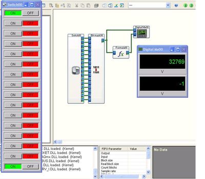
Try rather my mathematical formula. This is just a single module.
I used a switch and the module of bitmask for the set of integers.
Tags: NI Products
Similar Questions
-
HP 48GX no indication that a single number on binary inputs
Hello
It is possible that your BASIC Wordsize is set to a small number. MTH-press, BASIS of selection, press on NXT, you should see RCW and STWS, i.e. remind Wordsize and value Wordsize. Wordsize is adjustable from 1 to 64. The default value is 64. (type 64 and select STWS).
See pages 3-265-3-335 in the HP 48 G series advanced user Reference Manual
Note, not all resets will define the default settings, only a complete reset of the LOSS OF MEMORY will do.
.
-
How to convert a 32-bit binary number or Hex
Anyone know if LabWindow CVI has a function to convert a number: integer, real, double (can be negative), binary and HEXADECIMAL? Or an example of code to perform this operation. Thank you
Dear AI S,.
Thanks for your info. It will work.
-
Binary read with one of the many possible definitions - or - how ot loop over different groups?
Hi all
I have a group of different data types that I save as a binary file and read it again at a later date with an another VI. I saved the definiton of cluster with a typedef, so I am sure that I use the same type of reading and writing.
Now, I needed to change the cluster in the writing program should include another value. However, I still want to be able to use the VI of reading to read the old and new data files. I also have the opportunity to change the definition of binary file in the future (in VI writing) and be able to quickly adapt the VI to read the new definition while maintaining compatibility with the old.
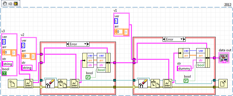
My plan was to have a typedef of the pole for each revision, say v1.ctl, v2.ctl, v3.ctl...
Suppose I have a binary input file that has been saved using one of these typedefs but I don't know which. I now open the file and try to read its binary contents with each of my typedefs for data type and to stop once the reading of the binary VI gives no error. Then I would translate this cluster to the definition of cluster current version by wiring through existing values and assigning values of model / default for variables that are not on the binary file.
My idea on how this could work is described here, with three versions of filetype:
For each new version of filetype I would need a new business structure although the content of the business structures is almost identical.
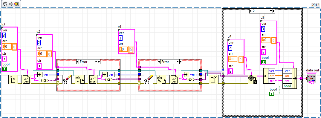
Because I save the file type definition version in my files, I could even simplify and use a separate case structure to update the data and fill in the dummy data:
Now the error structures are completely identical, only their inputs differ by type. How can I work around this? How can I loop over the typedefs from different cluster effectively?
I use LabView 2012 SP1.
Since you already have a version of the cluster, just read this byte digital itself and then use a case structure date back to before the version and read the entire cluster based on whatever the version of the type definition read you.
-
Problem with detection of changes in a loop
Hey,.
I have a NOR-9423 module in a cDAQ chassis (not to mention that of other modules), and it is used for the detection of change for a binary input. That's a little busy, coming from an engine step by step via a digital i/o. I want to enqueu a certain task when the busy bit goes from low to high and another task when it goes from high to low.
The problem is that my VI everything stops and waits for detection, as the error did not go through.
If I put a - 1 for the timeout, then of course everything block also, since reading that VI waits indefinitely change.
So basically, all I have to do is detect a change of edge and put an appropriate task in the queue.
Any help, thanks...
You must move the "beginning of entry trigger" and the associated logic (enqueue) in a separate loop. This will allow the logic to run its own while you wait for a trigger to start upper.
-
Colleagues programmers,
I'm looking for advice how to manage the following scenario using LabVIEW.
We have a system of great glove with hundreds of hand valves, automatic valves, sensors pressure/temperature/humidity, flow meters and regulators, pumps, vacuum, etc... There are so many thousands of objects in this system. We use a distributed control system of Siemens with high safety requirements (manipulation of radioactive gas). We will access the system using Siemens called Simatec PCS 7 via a multiscreen terminal software.
I'm not allowed to change anything on these Terminal computers or install LabVIEW or own applications on them.
The problem is the search feature very limited in this PC software, so I intend to develop a LabVIEW application to be used on a separate laptop computer to help new members of staff and students to find the exact location of the handvalves, etc. in these large boxes in gloves. This application would have a search box, where the user can type a keyword like "HV487", for example, and demand would then show the location of the object on the piping plan ('P & ID') and also provide information to the user where in the real physical glove box (as the "glove box, block A, North side lower quarter") ", etc...).
I can export the screenshots of the Siemens system and save them in form of pdf files or images. The P & ID size is of about ~ 50-100 monitoring screens. When the user makes a search for an object, the application should show the screenshot for the location highlighted in it.
I wonder what is the common procedure to program this request? I guess I should create a kind of table of research, a complete list of the valves, etc., and which contains the file reference picture, more the XY of the position of the object in the image pixel? It would be nice also to program an app LV I think for help creating this table of choice, such as by clicking on the image and typing the name of the object...?
Thanks for any idea further and advice!
Best regards
What is your question?
What should be the application architecture?
I think you did: table of correspondence, correspondence article name with screenshot file name and photo details. Maybe you will need several references image for an article.
How you store the lookup table?
Table of the text file, database, table of cluster binary inputs (my vote) or the style ini file.
How to display and highlight image?
The simplest is the base image optimization. You can scroll to the desired position (the 'origin' property) and draw a circle anywhere you want.
Advanced, but more capability is IMAQ, functions of overlay image display and zoom will be useful.
How to add article?
You can define the interaction of the mouse with display of the photo or picture, get the location, then add the entry in the table.
-
On my computer, the Caps Lock key isn't is no longer anything.
Troubleshooting steps:* Exchanged several keyboards. Same problem with everyone.* Tried the virtual keyboard Caps Lock (doing a job and even lights the indicator light on the physical keyboard).* Unplugged, replugged USB cables different USB ports and restarted. No change.* Use Device Manager to check for driver updates. No updates found.* A searched USB / keyboard settings in the BIOS to turn on or off. None found.System Specs:* Dell SK-8115 keyboard
* Windows XP Professional 5.1.2600 Service Pack 3 Build 2600* Dell Optiplex 760In Windows XP (and some others), there is a registry hack to disable the behavior of the keyboard Caps Locks with a binary input Scancode . If you are comfortable with taking a peek inside your Windows registry database, open RegEdit and navigate to,
[HKEY_LOCAL_MACHINE\SYSTEM\CurrentControlSet\Control\Keyboard Layout]If there is a Scancode map key, first export it if you have a copy then delete it. According to me, only a reboot may be necessary to have the new parameter of rereading in the system.FWIW, this is not normal behavior and if you have a Scancode map key, it was put there by a person or a program. You might want to consider the issue. Also note that there are available for the keyboard and a Keyboard Layouts registry entries. You want the old (in the singular). -
Hello
When we run customer BQY Web Interactive report. We get the following error.
Server error [2009]: Exception in validateDBUser: Com.brio.one.services.das.proxy.DasCommException.
Please help me.
Hello
Yes, we need 32-bit Oracle client to connect to the Oracle 32/64-bit client. Because the IR is designed to work with the binary 32 bits ONLY. Also make sure all the environment variables, have 32-bit binary input prior to the 64-bit
HTH
Kind regards
Zohra.
(Mark this useful. If it really helped you)
-
Install the IFEN SYSTEM on Linux
Hello
For the test I want to install a server of RDB database on a desktop Linux, is this possible?
Thank you.Search for BLOB to http://download.oracle.com/otn_hosted_doc/rdb/pdf/sql_ref_v72_part1.pdf
In a list, you can store unstructured data such as large amounts of text,
long strings of binary input from a data collecting device, or graphics data.
Any data type can be stored and retrieved from a list. The data is stored in
unstructured bytes. For example, you can store character data in a list and
then interpret it as hexadecimal data. Except for the length of the segments,
Oracle Rdb does not know anything about the type of data contained in a list.
There is no limit on the number of segments within a list.
Each segment stored on a page is referenced by the line index structure, which
uses a word offset and a word length. The page structure imposes a segment
size limit of 65,535 unsigned bytes.
I wouldn't do anything with rdb unless you have access to a person with experience.
-
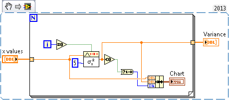
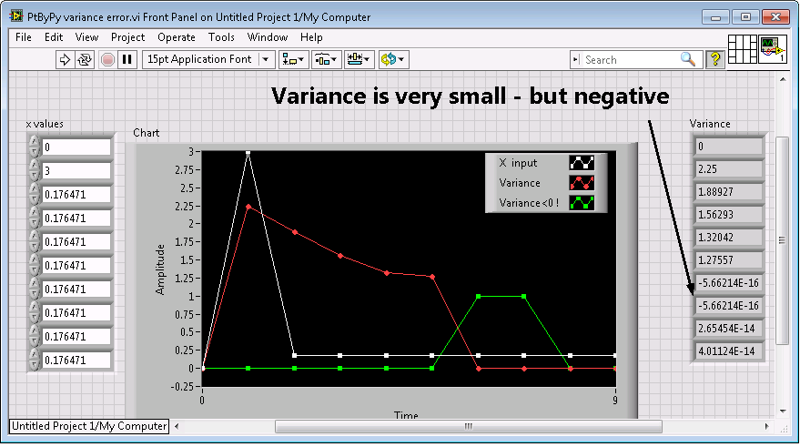
'Variance PtByPt.vi' generates values of negative values for some input
With certain sequences of input values the Gap PtByPt.vi can generate negative values. It is because of the precision in calculations.
Because it is very common to calculate the gap by taking the square root of the variance, this behavior can take you by surprise because the result will be Nan and not almost 0 you expect. According to the data, this may be frequent or very frequent. In general, a nuisance to debug.
The remedy is simple: take the Abs() before the square root value. A vi that demonstrates the case is attached.
I would suggest to include this correction (or similar) in the "Variance PtByPt.vi' because it gives rise to unexpected and hard to find errors.
By definition - variance cannot be negative.
CAR 446514 discussed in this thread has been corrected in LabVIEW 2014. For a more complete list of bugs fixed in LabVIEW 2014, see 2014 LabVIEW bugfixes. You can download a copy of LabVIEW 2014 evaluation at http://www.ni.com/trylabview/ or if you have a previous version of LabVIEW installed and an active subscription to SSP, you will be able to download the latest version of LabVIEW through NI Update Service.
Kind regards
Jeff Peacock
Product Support Engineer | LabVIEW R & D | National Instruments | Certified LabVIEW Architect
-
Best way to encode several digital inputs of choice / binary indicators
Hello.
I need some suggestions.
We have several libraries API (to control our material) written in C and distributed as a dll. For many of them, we have a library of LabVIEW VIs wrapping (using the call library function node).
We have several functions in which the entry (in the original C library) is an unsigned integer, which is supposed to be several flags ORed together (each value one bit).
I've seen more than one title, that this interface has been transferred to the wrapper live
1 digital input. User must understand and use it exactly like the C programmer
2 try to make more enjoyable - an entry that is a table, which appears on the front panel, as a sort of list box multiple choice of entry (internally in the block diagram that is used to create the correct entry to the C function)
I think there are others, but this is what I remember right now. When I saw option number 2 (looking at the front) I thought it was much more enjoyable. clearer and more intuitive (the user can select choice named, no, not strange %valeurs hexa%, etc.). However when I put on a block and tried to wire diagram, I had to provide an array of numbers; I had no idea what the values were supposed to be. Option 2 seems so much better for a user interface, but for an API, I think it's actually worse.
What do you see, if you were a programmer building my functions into your application?
Thank you.
Batya
Since each value is a bit simple, I would say that the wrapper have Boolean values in the connector pane and convert it internally to the correct bit field. Another option is to use a cluster of Boolean, but which may be less friendly to the user of the API. I suggest you do this only if you have several options.
-
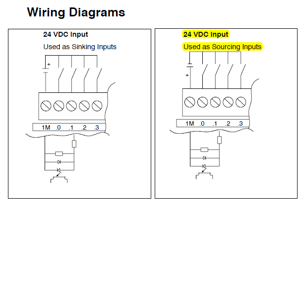
Use cRIO module NI 9477 as relay to provide 24V input for Siemens S7 - 200 (CPU222)
Dear all, could someone please confirm my use of NI 9477 as a relay works or not with the following details. It might be stupid question, but I do not know it is not displayed before and I can't really afford to burn my modules. I have two concerns, it's sink or connection to the source, another is the question of overcurrent.
The Siemens S7-200 is used to control an engine not by sending impulses. I provide two digital signals to control the direction of rotation of the motor. So I propose to connect my NI 9477 as illustrated in the graphic below (left configuration) relay switch.
According to the data sheet NI 9477 (attached), I suppose I should connect it as the right configuration for NI 9477 sinking module. However, power running electric in the control cabinet is wired as a configuration on the left. I don't know if I can connect to my NI 9477 or I need to set the polarity of power supply.
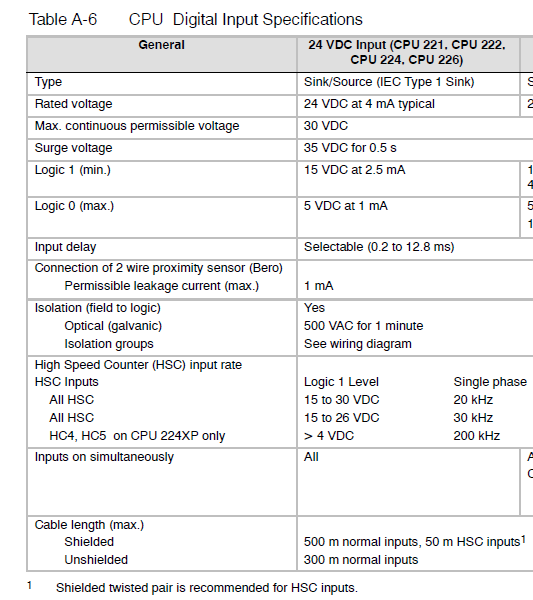
Another concern would be the current that runs through NI 9477. He rated at 1 a and will be connected in series with only a power supply 24VDC input digital s7 - 200. I don't know if the current could be a problem as in s7-200 datasheet, it seems that the current is only 4mA. I'm reading this correctly? I've also attached the s7-200 Datasheet if you have time to varify that, please.
Thanks in advance for any help.
Kind regards
Jinyu
Personally, I would just change a 9476. 9477 module looks like it's better for negative logic (24V = FALSE, 0V = TRUE).
And running for the PLC is practically in the noise of a digital signal of 24V, so I wouldn't worry on this subject.
-
Negative results with strain gauges
When I run my VI the results are always negative. I use the NI9237 with the NI9945. I wired my installation as one quarter bridge. There are three wires from the strain gauge. I went on the wires and I think it's okay / characteristics of NEITHER. Is there something in the MAX that I should be looking. Not sure why the values are negative.
Thank you
Harry Stone
Hi Harry,.
There are a few things I want to clarify:
-Traction deformation is positive and compression deformation is negative, what is described a high level in the tutorial below.
Strain with gauges
http://zone.NI.com/DevZone/CDA/tut/p/ID/3642As strain compression is negative, you would see negative within MAX results if your strain gauge knows any compression. Please keep in mind that a shift can be associated with each transducer, that's why some sensors use a calibration certificate. It is produced by the manufacturer and is provided with the sensor as is the specific sensor. The sensor goes through a testing process to determine its actual response compared to the ideal. In this case, a scale of table can be created to include these values.
How to do a custom able scale & Automation Explorer (MAX)?
http://digital.NI.com/public.nsf/allkb/3F6558112FD2C776862575B5004F7F87?OpenDocumentNot all manufacturers of sensors provide a calibration certificate. Or you can create your own table by placing known quantities of pressure, force, etc. on the sensor and map it to the corresponding voltage, or you can create a linear scale in MAX adjusting the intercept (b) the value necessary to remove any compensation.
You use the NI 9237 that compensated supports deletion. A null offset is executed with the sensor fixed without load placed on the sensor. Actually, a measurement of voltage is taken and this value is subtracted off the coast of each subsequent measure therefore removing the start offset. This takes up space you creating a linear scale and in doing so manually.
The two links below show how to use a custom scale created in MAX in LabVIEW, as well as coding the custom in LabVIEW scale to remove the dependency of MAX.
Acquisition of DAQmx with custom scale
http://decibel.NI.com/content/docs/doc-3706Create a linear scale customized for each channel AI in LabVIEW using DAQmx
http://decibel.NI.com/content/docs/doc-11136I recommend using a task sequence. Input parameters for the information about your strain gauge needed to perform the conversions of strain. There is an example of a measure of deformation in the example Finder LabVIEW (* open LabVIEW * help > find examples) designed specifically for the NI9237 that incorporate deleting the offset and shunt calibration devices. If you do not have external wires connected for calibrating shunt such as cited in this document , you will receive an error. Here is an explanation from the NI-DAQmx help Shunt calibration (start > all programs > National Instruments > NOR-DAQ > NOR-DAQmx help) to help better explain this feature.
Shunt calibration (adjustment of Gain)
You can check the output of a measurement system based on a bridge by comparing the measured output bridge with a calculated value if the physical load on the sensor is known. NOR-DAQmx can then use the difference (if any) between calculated and measured values as a factor of adjustment of gain for each measure. You can simulate the application of a load at the bridge by connecting a significant resistance in parallel with the bridge. This resistance, known as a shunt resistance, compensates for the voltage from zero of the bridge. Because the value of the shunt resistance is known, you can calculate the physical load corresponding to the voltage drop of the resistance.Use the Shunt calibration perform the Assistant DAQ or DAQmx VI/function to perform a calibration shunt, which defines the the gain setting for a virtual channel. NOR-DAQmx then uses this adjustment of gain when you descale readings from the bridge. Some National Instruments products are internal resistance.
This may seem like information overload, but I wanted to provide you with a detailed explanation of your understanding, in addition to immediate responses. As a logbook, I recommend that you use the 9237 strain example and use the removal compensation. Negative values are expected for compression and positive for blood. The handy Guide below gives an excellent overview of the strain gauges, which also includes a video.
Measurements with strain strain gauges: practical Guide
http://zone.NI.com/DevZone/CDA/tut/p/ID/7130Hope this helps!
-
various input file formats to diadem
Hello
Am new to this area of DIAdem. I read that DIAdem takes input .dat, .mme, .xls and .iso.
Can someone make me understand that, so that these different input files are used and how they differ from each other? What type of file is more efficient to use?
Hi Rash.patel,
They CAME to files, so if you have this file type on your hard drive, you can load it into DIAdem. If you have a choice of file formats, NOR recommend TDM/TDX or PDM. List you provided, the former DIAdem *.dat file format is preferable, because it's the only one in the list of stores as a block of data in binary files, which makes it much faster to read and write.
What type of data files you load into DIAdem to analyze and report?
Brad Turpin
Tiara Product Support Engineer
National Instruments -
Digital FPGA of entry of the negative voltage
What is the maximum negative tension that the digital input on the FPGA can take without damaging it? I tried to look in the data sheet for the sRio 9636 and I can't.
Thank you
Hi, Berthe.
The sbRIO-9636 was DIO only on the OID (J502) and connectors MIO (J503). It's a bit different from the other variants sbRIO-96xx that others may have a RMC connector that has additional DIO.
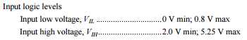
Connectors IDC 50 pin DIO and MIO are 3.3V pins, but they are 5V tolerant inputs we have protection on the IDC DIO connector. VIL values and HIV are specified in the data sheet:
http://www.NI.com/PDF/manuals/373378d.PDF
These are the recommended conditions of use. If you need to know the maximum negative voltage to determine if your landing short of the runway is acceptable, this number to an absolute minimum is - 500 mV. I would recommend you choose the appropriate to your driver series termination resistors to minimize landing short of the runway, however. The absolute minimum even applies to the 3.3V RMC DIO as well.
Maybe you are looking for
-
How can I determine the amount of GB came in my gen 4 iPAD wi - fi only
-
Upgrade WLAN to the Satellite Pro A30
Hey ppl. I have Toshiba Satellite Pro A30 (SPA30). Where I have the slot for the wireless card?I want to buy via e - bay, but I don't know what kind.If anyone can let me know, thanks.
-
What's up with Support technique Apple?
I have a MacBook Pro for mid-2009 running Mavericks 10.9.5 and iTunes 12.3.1. It has been suggested to me that my old MacBook plays perfectly with the new OS and the version of iTunes and that I should come back to Snow Leopard and an older version o
-
Original title: help me please, someone stole my facebook password, how can I get a new one, they are at the origin of the major problems. Please how can I get a new password Please, someone help me. Someone had taken over my face book password and c
-
Use 3.5 mm Combo Jack Microphone
I have a HP Envy M6 1106TX with 3.5 mm combo jack. I tried to plug in a microphone line but windows configures default as output. How I put it so that I can record the line without needing to purchase a cable splitter?