DAQ Assistant as a selector of case
Hello
I'm reading an entry to my daq assistant digital camera, and then to hold for x number of seconds, up to that time. The entrance to the wizard matter not after the first entry.
So, I used a switch case and started trying with a virtual switch. Everything worked fine... until I begin to try with the daq assistant. The output of a data acquisition assistant is a table 1 d of boolean. The entry for the case selector is a Boolean value.
It is possible to select the cases according to the output of the daq assistant? If it is true, how can I do this?
Greetz Margaret
I added a table of index to your code that modifies the array to a single digit. Remember that this only gives you the first digital input. If you switch to a different channel, you'll have at this table to a different number of the index.
Second time isn't a very good way to measure time so I changes the way vi a measure of time.
Thirdly, the outside while loop is not necessary. The two loops will be run until you press the stop button. I think about the use of an event to capture the stop function so that you don't need to a stop button.
Tags: NI Software
Similar Questions
-
DAQ Assistant no recorded data during the case structure is false
I try to turn it on turn off heater using intermittent relay module (some time and some free time). The program attached that do very well. Except that I also want to record the temperature of the radiator using materials DAQ Assistant and it records all the data when the case structure is false. I mean, when the relay is off. I tried to use the vi for the acquisition of data in the structure of the case. However, aparently it is not possible to call the module analog input even twice in the same program. All solutions? Thanks in advance.

-
Simulate signals wired to the DAQ assistant for USB-6009 device
Hello
I'm trying to send a signal to the DAQ Assistant Express VI. I watched the movie "Generating a Signal" on the Web site of NOR (www.ni.com/academic/students/learnlabview/generate.htm) and I have my Signal simulate connected directly on the DAQ Assistant, as shown in this film. In my case, the DAQ Assistant sends the signal to a device USB-6009.
However, I received this message:
Error-200077 occurred to the DAQ Assistant
Possible reasons:Requested value is not supported for this property value. The value of the property may be invalid because it is in conflict with another property.
Property: SampTimingType
asked the value: Sample clock
You select: On-demandIf I select 'On Demand' in my DAQ assistant and run the vi everything works beautifully. However, I need my DAQ assistant to be configured to generate a waveform AC continuous, not output a single alternating current rippling.
What happens here? I did not have this problem before on other devices of NOR. I am using LABView 2010.
Please answer.
Thank you.
-
module relay and DAQ Assistant
Hello world!
I am a beginner, and currently dealing with simple business priori Labview. Recently I got a USB relay Module must be integrated into an alarm system. Let's say that if we get some more value than the other, the relay must be closed and activate a siren (see attached example). For this I used the DAQ assistant and set up one of the output channel of the module. Using a simple Boolean switch, I can easily open the relay and close. However, if I use a case structure, an error is obtained, as the DAQ Assistant for an outing can be only used once. I mean, if the relay is closed and I want to go back to the initial situation, i.e. open relays, what should I do?
Schematically:
-If A > B, then closed relay
-If has
Sorry for the explanation of disorder, but I think you get the point.
Thanks in advance
I just got. The problem was that in the main vi, not in the example that I have attached, the same output via the DAQ Assistant has been configured for two structures of different cases. Obviously the relay module was going completely crazy, since I had two independent pairs of TRUE and FALSE labor at the same time. If I get, for example, TRUE for one structure box and FALSE for the other, the switch knows not what to do. I hope it is clear now...

-
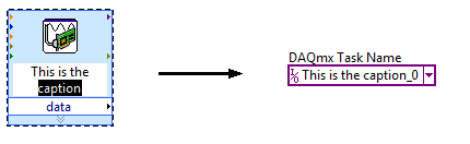
Task of naming of the DAQ Assistant
I not bad by using DAQ Assistant to create a task to do what I want, but I can't understand how to give a meaningful name to the task. The name of the task seems to be assigned arbitrarily to something like "Assistant_1 DAQ", which is not very useful for me.
Please advise on how, in the "convert to NOR-DAQmxTask", procedure I can assign a different name to the task. If not, is it possible to rename an existing task?
Hi wildcatherder,
There is already a way to set the name of the task in the present case, but it is not quite obvious and has a little whim. If you change the legend of VI DAQ Assistant express before selecting "Convert to the NOR-DAQmx task", he uses the legend that you specified as the name of the task in Max... and then he adds "_0" at the end:
If you have a suggestion to improve this feature, perhaps you could post it to the Exchange of ideas, information Acquisition?
Brad
-
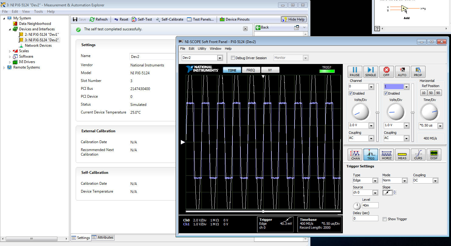
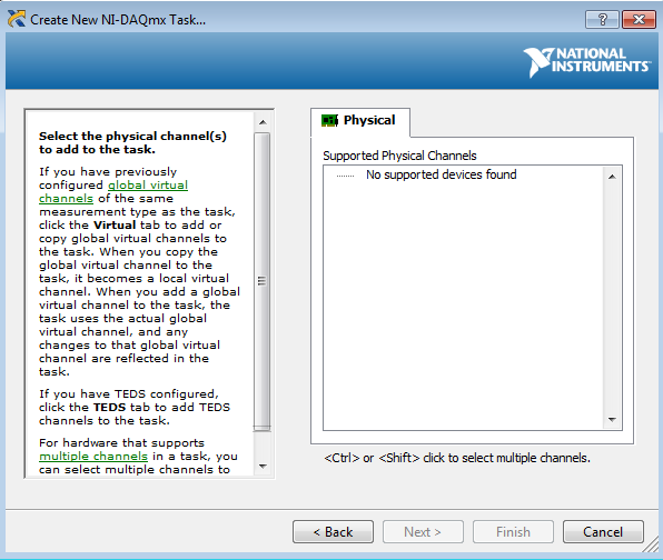
I am trying to create a development machine, where we can test the new code without using our physical hardware. I followed this guide to set up a system of simulation. I get to step 3.2 b, but the device does not appear in the DAQ assistant. MAX, the device self test and gites calibrated successfully, and when I open the test panels, I see some sort of signal. I guess that's a default entry simulated since I didn't that device to look for anything? Note that two devices, I am creating the show upward into the devices section and Interfaces, but that, even after running auto calibrate, automatic Calibration date is not yet specified.
When I try to test the device and create a voltage according to the guide, I can't see a device in the creator of data acquisition task.
Steps 1 and 2 of this guide are of course met. Step 3 is not, but this is not surprising because a simulated device is in device in any case manager. Also, I'm not under RT, so step 4 is satisfied.
Someone at - it ideas?
That would be because the PXI-5124 is a digitizer not an analog input device. You must use the NI SCOPE not NOR DAQmx driver
-
Consecutive calls to DAQ assistant
Hello
I'm working on something that is very probably simple. Maybe the problems stem from a bad initial design choice. The VI (and subVIs) are used at a voltage output, read another tension and react accordingly.
First the error I get is "error-200547.
Here's how the program works:
1 MOVR.vi
This generates two analog output signals, controlled by the same signal generator. There is also a digital signal, but I don't think that's the problem.
2 MTUL.vi (and MDTL.vi)
These use MOVR and read another voltage. Essentially, the voltage must be created until the limit is reached, and he decides to stop.
These two work as expected on their own.
3 IsoMeasure.vi
This is where the problems occur. Basically, this VI take MTUL and MDTL and makes a loop in a loop for, change the frequency of each increment. The observed performance is MDTL will work and try to start MTUL. It's when 'Error-200547' is thrown. The error code appears to be understandable, but "autostart" isn't clear for me using the wizard.
I would avoid using all daqMX code, but I will if I have to. If that's the suggestion, a good example is that sort would be great. If I can put the autostart Assistant, I guess it would help as well.
Thanks for all the tracks. I think it should work.
Hi drevniok,.
The reason why you get this error is that you try to restart your DAQ Assistant several times in your application. One important thing to note is that a task DAQmx configured and started only once each time the DAQ Assistant is called for the first time. Therefore, since you are stop and start the DAQ Assistant, in your application, the second time you call the wizard, it does not start the task. This is made more so by the fact that the function of writing in the DAQ Assistant DAQmx has his automatic starting of entry set to False.
Using the DAQ Assistant for Analog Output returns an error-200547
That being said, the DAQ Assistant is mainly used as a quick and easy to set up and use your DAQ hardware, however, it is a bit limited in functionality compared to the lower levels DAQmx live. This is a case that illustrates this limitation and therefore, I believe that the best solution this problem would be to use the DAQmx LabVIEW vis a lot shipping examples that can help you get started developing your application. These lie in you NEITHER example Finder under the menu help. "" The example I want to show you is the Regeneration.vi Clk - no Cont Gen Wfm - Int voltage under input and output material"DAQmx" analog generation "voltage.
Is another resource, I want to tell you the getting started with NO-DAQmx: Homepage, which are a collection of tutorials online on DAQmx programming.
I hope this helps.
-
Calendar and the problems of data collection with the DAQ Assistant
Hello NOR Developer area,
I am a Novice of LabVIEW and have seen how helpful you all can be, and if I come to ask for your help.
I'm having some trouble with a VI I built that specifies an input voltage, a SCB - 100 connected to a PCI-6031E and converts this tension in a temperature displayed on a waveform table. The goal is to give a constant reading of the temperature and display it in a chart for as long that the VI is running (and to reset the chart the next time the tracks of VI).
The problems I've encountered currently are:
-After a few minutes of the VI running, I get an error message 200279: tried to read samples that are no longer available. The requested sample was already available, but has since been replaced. (to the DAQ Assistant express VI).
-I don't know how to change my chart so that the minimum value X is both during which the VI was launched and have the maximum X value increases with each iteration of the loop. Currently, I have the VI get the time system and contributing to the property node X scale. This worked for the graph of the voltage, but not for the temperature chart
I appreciate those of you who took the time to read my post.
Thank you all for your help.
Sincerely,
Ethan A. Klein
SB candidate in Chemistry & Physics
Massachusetts Institute of Technology
Class of 2015
PS I enclose my VI to give you a better understanding of my current situation.
E A Klein wrote:
Thanks for writing.
What property node is talking?
I do not understand that many different data types. How can I go on the treatment of all the data?(Did you mean I should wire 'blue' data for mathematical functions rather than using the node property tension?)
Sincerely,
In fact, one of the nodes property. I mean specifically the tension property node. But in reviewing, I noticed the other nodes in property for the chart. Just set auto-scaling to the X scale and that should take care of two of the nodes property (right click on the graph, X scale-> AutoScale X Scale). I also recommend placing your mathematical functions in a Subvi to make things easier to read. Attached, that's what I think you're after.
I hope that these small tweaks will speed things up enough to avoid your error. If this isn't the case, then we should begin to look at the design of producer/consumer model or take readings at the same time. It might also be worth looking away the DAQ Assistant and DAQmx real screws. But one step at a time.
-
Recovery of the DAQ Assistant data acquired
Hello
I'm currently dealing with a continuous data using NOR cDAQ-9174 proposed acquisition and recording of analog input signals of a built-in three-measuring probe.
I built a simple vi using DAQ Assistant to acquire data and write to an output .txt - rather than .tdms using Signal Express.
On a day 10 cycle of data acquisition computer was mistakenly turned off - leaving the empty output .txt file. LabView recovered the VI cut and I wonder if there is a way I can access the data that has been saved by the DAQ Assistant which can be saved in temporary files etc..
I have no idea where that might be, since you cannot delve deeper down into the 'levels' of DAQ assistant as you would a sub - vi.
Just as a note aside to apologize my stupidity - I realize that all the data at the end of the writing task is stupid and completely avoidable... but I worked for a date limit.
Thanks in advance for any help you can provide.
Dan
The most likely answer is not, unfortunately. It looks like you were a table of data at every point of the construction and then measure he writes at the end. In this case, unless you have explicitly recorded data in a temporary file, it is located right in volatile memory, waiting for you to do something with it.
I realize that this isn't what you want to hear, as it comes to the time of submission of draft / year...
If you post your VI (preferably version LV2012 or below), I can have a look to see if there is anything obvious.
-
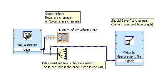
I did separate VI for reading signals from several channels on a map of NI USB-6251. I would like to combine these in a VI VI alone so that they can run that at the same time, however, there is an error if there is more that a single DAQ Assistant in the same--> error-50103 VI was held at DAQmx controls Task.vi:32 (the specified resource is reserved. The operation could not be performed as indicated.)
All the inputs of channel must then be read in with a single DAQ Assistant, but all of the data on different channels are not separated. Can save this data in a matrix or otherwise manageable which allow to facilitate the analysis of the data from the separate channel entries?
I tried to view the data in a file of measures, but then when I tried InPort data, I could all the data I wanted.
Hi AggieGirl,
Good afternoon and I hope that your well today.
First of all, you will not be able to have more than one DAQ Assistant by input analog or analog output task because the device has only one of each. So, you must have a DAQ task to HAVE and AO. (This is not the case for DIO static).
There is far from split signals using the express VI - signal splitter.
When you say you saved this file and it does not work, how it did not work? The Express VI - save a file of measures needed to manage multiple waveforms. Can send you your code & explain more about what was not OK on the file?
Thank you
-
Disadvantages of using DAQ Assistant
I need 2 analog inputs continuously at 5-10 kHz from the sample and then use a combination of producer consumer and State Machine for the processing of data in real-time.
In most parts of the example I've seen, people always use Subvi of data acquisition groups. Even though I know how to set up getting data using the Subvi, I like to use Express VI DAQ Assistant to perform data acquisition.
Known disadvantages of the use of VI express in my case (see 1st line)?
With the help of an express VI will slow down time of execution and, therefore, your time of iteration of loop due to the fresh general partner. If you are concerned about the timing of your program, then you should strongly consider using the DAQmx API screws.
-
Hello
Recently, I bought a PCI - MIO - 16 - 4 to fit our labview7.0 DAQ. After installing the driver (from the CD), the card works fine with MAX and labview signalexpress. However, the default program is not at our request.
So, I tried to schedule with labview7.0. I found that a single critical module, assistant DAQ, is absent. Therefore, I can not write the program. A strange thing is the DAQ assistant has already existed before using the installation CD. But then, he disappeared. I don't know how to find the DAQ back Wizard.
Until we bought the card, we especially asked in advance if it is programmable with labveiw 7.0 or not. The response has been positive. Can you give me a suggestion or a solution?
You need just to be sure that you have installed a version of DAQmx which is compatible with LabVIEW software:
NOR-DAQ & compatibility of the versions of LabVIEW (for Windows)
If yours is compatible, then try to reinstall the driver. I'm sure that will be the case MAX and LabVIEW SignalExpress work.
-
DAQ Assistant is not in LabView
Hi all
I use NEITHER cDAQ-9174 and NI 9203. I have already installed the driver for the NI 9174 cDAQ, which is NEITHER-DAQmx 9.8.0. I can see the device when I opened NI MAX. However, when I open LabView 2015, I can't find DAQ Assistant in the function Palette. I noticed on the chassis, 'ACTIVE' light is not on while two other "POWER" and "READY" light is on. I look in the forums OR but I can not find the solution.
Any suggestion, please help!
Thank you!
DAQmx 9.8 is not compatible with LabVIEW 2015. You must use at least DAQmx 15.0. See here for more details: NOR-DAQmx and LabVIEW compatibility
-
201003-error occurred in the DAQ Assistant
Hello. I use "cDAQ-9178" and "NI 9215" and "NEITHER 9402" are added on. "
However, when I run Labview code, "Error-201003" occurs.
{
Device not available. Possible causes:
Device is no longer present in the system / device is not powered.
Device is turned on, but was temporarily without electricity / device is damaged
}
(Error appears as the 1st and 2nd figures below).
(Plans of logic is the figure below).
Thank you.
I could be something with the pilot
Check this box:
Error 201003 to the MAX test panel or all by running the DAQ Assistant
http://digital.NI.com/public.nsf/allkb/5413F392D88326148625746B006745C5
In this forum, they speak the same error:
Spontaneous error code 201003 for acquisition of data PCI configuration
http://forums.NI.com/T5/SignalExpress/spontaneous-error-code-201003-for-PCI-DAQ-Setup/TD-p/830707
-
Control relay with Boolean switch using DAQ assistant 9481 - problems
Sorry for what may be a stupid question but I'm stuck in quicksand.
I use a relay module 9481 and have two external relays connected lines 0 and 1.
When I create a digital output 0 line by line, I can run the test inside the express and activate the relay and turn off without problem.
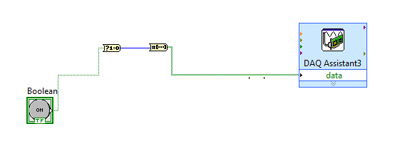
The generated block DAQ expressed expects a Boolean input of 1 d. (See attached photo).
I want to connect a Boolean switch relay line disk 0. You can connect live not because the switch is Boolean and the input is Boolean 1 d - I'm a conversation in the pict.
All plumbing lines display results, the relay never active.
Any bunch would be greatly appreciated! Thank you
Mr._Mechanical,
Welcome to the Forums of switch OR this forum is generally intended for products OR-SWITCH [such as the NI PXI-25xx & NI SCXI-11xx], I think I know the answer to your question.
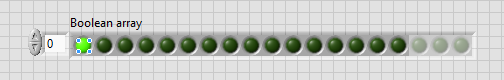
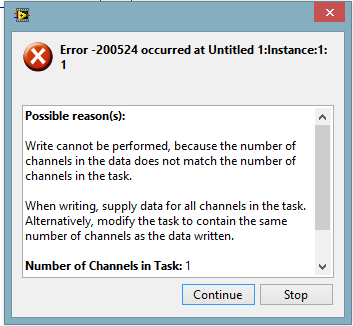
I think the reason why it's a failure is the conversion you make generates a table of 16 Boolean [as the 'boolean to (0,1)' function creates a data I16 type] with your data more false data points 15.
When you try to control the relay, he sees 16 datapoints are you Commander to a single port [channel] and so error out.
My suggestion would be to use normal DAQmx digital output screw [with, he set up as ' Digital > single channel > single sample > Boolean (1 line) "] rather than the DAQ assistant.
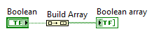
If you use the daq assistant, simply by using the function 'Building the table' will transform your simple Boolean data point in a Boolean array containing a single element.
While the DAQ assistant is very easy to use, I recommend that you use the DAQ assistant, because this reduces the features and increases the execution time.
Maybe you are looking for
-
I need to delete a message in the forum, because it refers to a work site.
-
Some Audio files are not eligible in icloud library, how can I force icloud to copy in my iphone. They are legitimate files (audio course)
-
KB22891, KB2466074 & KB2289163 Udates won't install
All recent (12/15) updates updates of the object will not be installed. I am running Vista sp2. I tried several times with the same results. The error code for all three is the same 646. Any help is appreciated... Thank you.
-
All my programs are trying to open with bsplayer, how to bring it back to normal?
I guess my husband accidentally makes all programs open by bsplayer while trying to open some games.
-
I have a HP G60-214EM laptop and cannot get it connected to my samsung 26 "smart tv. Can anyone help?