NEITHER 9213 acquire data of the CJC in mode Scan interface
Hello
I would like to ask if somehow possible to acquire data of CSF (voltage or temperature) of map sensors NI 9213 uses the cRIO (9076) scan interface mod or I have to develop my app using the FPGA?
Why do I need data CJC aims that I use thermocouple type L which is not supported by the card and so I need to have the thermocouple voltage and temperature of the CCM in order to calculate the temperature measured.
Best regards
Hello
The only way you can do this develops the FPGA application.
Why not use a different type of thermocouple?
Kind regards
Ion R.
Tags: NI Hardware
Similar Questions
-
acquire data from the oscilloscope DPO2024
I am trying to acquire data from the oscilloscope DPO2024 using labview. I am able to do, but my vi file only works for channel 1. Other than channel 1, it does not work and instead, it changes the adjustment of the oscilloscope as well. Find the vi files attached.
Any help is very appreciated.
You must connect the channel in the waveform of reading. It is default to channel 1 if thread continues.
-
How to acquire data from the memory of the meter
I am a beginner of Labview. I don't know how to acquire data from the memory of the meter.
I read a few examples of data acquisition, but apparently not similar to my case. I can't use DAQ in my computer, because I don't have DAQ card.
Could someone give me some pointers? Similar examples would be great.
-
Data acquisition using the USB-GPIB 82357 B interface for 4395 impedance Analyzer has:
Hi all
I tried to communicate Analyzer 4395A impedance with interface USB GPIB 82357 B using the command of expert keysight and Labview module tutorial. I couldn't able to find orders of SCPI (Standard for programmable Instruments orders) for 4395 A impedance Analyzer in the expert keysight command. Please help me on the subject of what are the other possibilities to acquire data from the Analyzer of impedance 4395 A using the interface USB GPIB 82357 B.? Is it possible to get LABVIEW plug & play drivers for USB-GPIB 82357 B interface? Our main goal is to control the parameters of impedance measurement and draw F vs IZI and theta vs F as well as get parameters of equivalent circuit on a PC with LABVIEW GUI.
Can't wait to help.
Hello!
I agree with 'heavy '. For more information on how to program a 3rd device contact the manufacturer because they have the knowledge. Unless there is already a LabVIEW driver for this device, you would have to implement that yourself and need information from the manufacturer.
Regarding your question if the GPIB-USB is unsuitable, it is quite easy to answer: If you want to communicate with a peripheral GPIB NI GPIB-USB can do this. But you would probably need a driver to use the GPIB of meaningful communication bus.
Best regards
Christoph
-
storage, reading and writing data to the file
Hello world
I am new to the Labview and his community. Asked me to acquire data on the measurement of the pressure using Labview. I could build the code and got it working, but when I look at my data that has been collected, there no stopping point. I just spent a lot of time looking at the data in the place where it begins and where it ends. The question I ask is how to create a code to read the pressure, storage, in memory until there finishes, collect data and then to write in a .csv file.
I use the NI USB-6009 case and hook upwards to ai0 and ai4. See the attached code so uncertain.
I want to record 100 data points and the system stops after these collection.
Thank you
John H.
You have a certain time which means your VI will continue to run until you press your button to stop the loop.
The DAQ Assistant is already set to 100 samples.
Just delete the while loop!
-
Hello world
Do you know if you can acquire data from a microcontroller that runs under the PLUS + 1 environment, using the NI 9201 platform? I need to build a test environment in labview, but entries must be purchased from the microcontroller MC024012 Sauer-Danfoss. The problem is that this microcontroller interface provides the programming amiente MORE + 1 Sauer-Danfoss. Can you help me?
Thank you
Elza Figueiredo
double post and bad advice
-
Get the highest value of acquired data
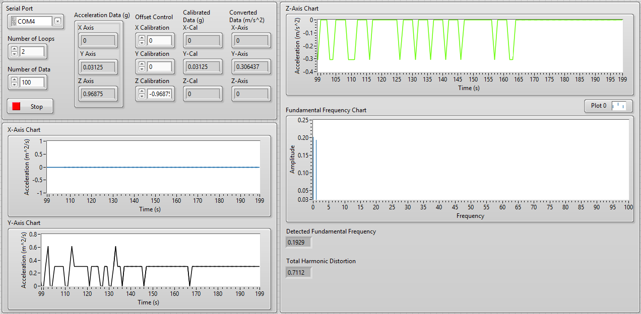
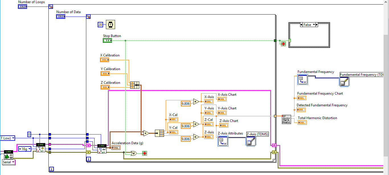
Hi, how can I get the highest value of data according to data acquired using the accelerometer ADXL345 and LINX in LabVIEW?
I want the highest data to be shown with a flag. However, the data being shown are always the last acquired data. My problem would be what happens if the highest data somewhere at the beginning or in the middle of all the acquired data? How to display the highest data using an indicator?
Here's a look at my front, block diagram, and sample of the acquired data.
From the front panel, the basic indicator of detected last poster 0.1929 (amplitude), which is the last value. But looking at the Excel file, the highest data are data which is 0.2013. The highest, I want to be displayed on the indicator not the last value. How do I do that?
Thank you!
I gave you an example of what you need to do - it is not okay if wire you the new value and the old value for the X or Y - it will always return the maximum of the two values so the order doesn't matter. It would have been more useful if you had posted what you tried the max & min. You need a registry to offset inside the loop (like I did with my while loop). If you only want to display the maximum value for each iteration of the loop for external, you must initialize the shift register by plugging a 0 to its terminal on the left. A shift register her pinned the value of the last run - probably not what you want here.
-
Operating system: Windows XP
Hardware: PCI 6259
Terminals used: PFI0 and PFI2
Counters used: Ctr0 and Ctr1
IM developing an application for the acquisition of data where timed loop synchronization source comes from my PFI2 (using the string A of an encoder). IM basically trying to acquire data based on the number of ticks from my encoder. For the synchronization source, I use counter 1 to capture the rising edge and have the loop time-acquisition of data. At the same time, Im using the counter 0 to count the number of rising edges so I know exactly in what tick data was acquired. PFI0 and PFI2 are connect to channel A of the encoder.
Questions:
Timed loop acquires data at each tick, because when I discover the data (text) file is missing count of my encoder value. Is it because there is a limitation on the Windows operating system? I used a noculars to measure the frequency at the maximum rotation of the channel encoder and 6,757 kHz. All solutions?
Also, is there anyway I can route the source channel internally an encoder to generate synchronization source instead of using another counter? I have attached my VI.
Hello
All the samples that you acquire will be read by LabVIEW in a sequential manner. Figure 4-21 on the M-series on page 80 (4-34) shows that you will acquire all the samples you request all channels that you enjoy in sequentially.
-
tracing of dynamic data but the diagrams showing the previous acquired data too
Hi, I'm developing a curve of voltage signal at the same time as it is acquired by the computer of the amplifier to locking SR830. I used a XY trace and placed inside the loop, where the data are acquired.
Please find the attached VI.
Cory K wrote:
Altenbach says:
The express VI 'built the xy graph' has an entry "reset?" Wire a real in order to reset the internal data. In your particular case, do a '= 0' on the final iteration of the Interior for the loop and thread it reset entry.
Now I'm confused. He does not want to keep the previous data or not?
He made it seem like it's getting only 1 point in the chart, but he wants to keep all the data in the chartSorry, my post was incomplete. You must double-click the express VI 'build xy graph' and uncheck'erase data on each call. Easy enough?


Whenever you want to start over, thread a real for the reset entry to clear the history.
-
To generate a sinusoidal waveform of given the frequency of acquiring data 6251
How can I generate a sine wave of given the frequency of acquiring data 6251? I tried to use the generation of waveform of the signal processing Toolbox, but it seems that it is written that the first or the last sample, not all. I have faced this condition when I tried to write through 1 d double multichannel analog waveform.
In the examples, look at Gen Con voltage Wfm - Int CLK.
If you continue to have problems, according to the code you have written.
-
DAQ Assistant Express Vi to acquire and generate data at the same time in LABView
Can I run acquire it and generate the Express Assistant DAQ Vi at the same time in a LABView program? I am using LABView 2010. It's acquire and generate a NI USB-6009.
Thank you
Mary
You can acquire and generate the same VI but obviously you can't generate a wave form unless you do a single point at a time inside a loop with a sample on request and can live with low samples/s specifications.
-
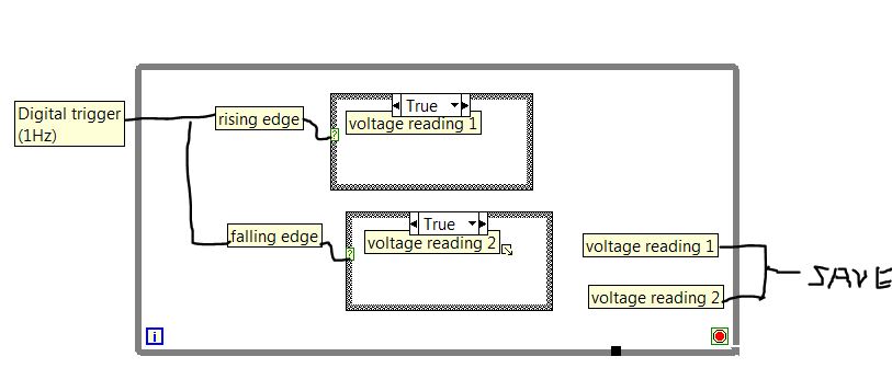
How to control the rate of acquiring data in a while loop
I'm trying to use a digital trigger to collect data on the rising and falling edge. The design is displayed as below. Now, I save the measured voltage 1 & 2 to the local variable in the while loop. Hoever, the while loop runs at a frequency of more compared to the structure of the case triggered. So I had a lot of repetitive data. If I record data directly from structure of the case, it will be recorded as data-0-date-0 because of the ongoing case of fake wire.
I wonder how to revise to save the measured voltage 1 & 2 at the same frequency of up/down edge triggered? Thank you! I have also attached my current version of Labview program, which takes place in time real Labview 2013.
Mcdullna wrote:
Thank you for the answer. Could you be more specific about the use of the shift register?
The case of false just past the value through. With this configuration, you agree that the data remain in the son, avoiding race conditions. It is also more effective than the use of local variables.

-
How to acquire data from both channels on a PCI-5922 (OR scope)?
I'm fairly new to LabView (version 8.5.1) and I'm working on my first vi non-teaching. I need to acquire analog of the two channels of a PCI-5922 data. I made a single channel using NEITHER brought Express, but you can use NOR carried Express to both channels. I tried two instances and that left me with a free entries or exits, I also tried to allow the two entries, but I get only one exit. I think that I don't have my head in the right place with this. Sorry if this is very basic.
Thank you... Steve
Take one of the LabVIEW base tutorials.
Simply use the Signal from Split. Of course, it's always this evil dynamic data.
-
Transfer of data from the old and new Mac
Hi folks, I'm acquires a new iMac, PC (with Retina 4 K display 21.5 inch iMac) to replace my current iMac (21.5 inch, mid 2010). I sold my existing iMac and will have to ship power off before receiving the new unit, ergo, I won't be able to use the method of transfer of my data from the old to the new Mac.
Accordingly, I am looking help form to advise me how can I do to preserve my existing Mac data so that I can install on the new Mac. In addition, how to delete all my data from the old Mac but preserve the OS X (El Capitan) and relevant applications.
All of the advice and recommendations will be greatly appreciated
1. create a Time Machine backup or clone bootable on an external drive, and then migrate your data from it.
2. you need to remove El Capitan of the old Mac before send you it off and return it to the most recent of its original operating system or 10.6.8.
(137493)
-
data from the buffer before graph it and block size
I hope you can help me with this situation because I was collapsed in this situation for two days and I think I see the light in the short time and time is a scarce resource.
I want to use a NI DaqCard-HAVE-16XE-50 (20KS/sec accordig to the specifications). For data acquired by DasyLab, I use OPC DA system but when I try to get a graphic from the signal I get ugly results.
I guess the problem is that the PC is not powerful to generate a graph in real time, is if there is a block to save the data, then graph the data without using "write data" block to avoid to write data on the disk?
Another cause of the problem, it might be an incorrect value for adjusting the size of block, but in my piont of view with the 10 kHz and 4096 block size is more than necessary to acquire a signal of 26 [Hz] (showing the photo). If I reduce the size of the block to 1 signal showing in the graph is a constant in the first acquisition value. Why might this situation?
Thanks in advance for your answers,
You don't want to use OPC DA for a device installed with the material. OPC DA is designed for industrial devices low speed, not for cards installed 20 kHz!
Rerun setup of DASYLab and select the OR-DAQ driver, deselect the NOR-DAQmx driver.
You must use the analog input OR-DAQ module for talking directly to the camera. You will get the full speed of the device, and the buffering is managed properly.
I have this card somewhere in a box, and when I used it, it worked perfectly with the NOR-DAQ driver.

Maybe you are looking for
-
Your new "signed apps" will not allow use of unsigned after the 41 version. This won't allow 'E - Web Print' Epson app right now, and the description says you will be disable rather than allow me to assume the risk. I like Firefox, but won't trash my
-
Tecra A8-104 requires no password BIOS or HARD drive
Hi, I recorded the two Bios and hard drive goes into security help Toshiba but when starting the system he does not ask me for any of them. No idea why?
-
SimplePass does not not on Pavilion m6-1035dx
HP Pavilion m6-1035dx Windows 7 64 bit When I bought my computer laptop simplepass used to work on my windows login and google chrome, but then for some reason any it stoped working on windows connect you, but always works for my google chrome. Then
-
My system restore restores not to any of the selected restore point. How can I solve this problem?
-
Windows allocate two disks with the same letter
I had a systems problem where the computer would not be arrested because of the computer by providing two different players with the same ID letter ("F") during the race. The program kept asking I have reformat the drive "F". I had a former player ID