NEITHER 9237 external excitement - VeriStand 2013 SP1
The voltage recommended for my pressure is + 10 VDC sensors. I prefer to use external excitation according to the NI 9237 manual, total power to the module is limited to 150 mW, which in my case is "four bridges complete 350 ohm at 3.3 V. (I'll use pressure transducers (4) 350 ohm full bridge). I use scanning for EtherCat engine and the NI 9237 in a chassis 9144 OR connected to a cRIO-9081. For troubleshooting, I have two transducers on a pressure calibrator and another RJ50 connection a NI 9949 escape. If I select "External excitement" and have my power supply of 10 V connected to the bass + EX, EX-connecteur, I get an invalid value for my pressure sensor. It is after the scaling of the calibration value. The gross value is also incorrect. If I let the value "External excitement" but shoot the EX +, EX-connecteur, the EX +, EX-tension (pins 6 & 7) will go to 4.735 V and I'll get a CORRECT pressure reading. If I select an internal 3.3V excitement, I'll get a statement of the correct pressure, but I am a little concerned about the resolution that recommended excitement is + 10 VDC for the pressure transducers. My question is: Why can't I use the external excitement? I have another application with a chassis PXI and EtherCAT and it works OK. I also tried to place a NI 9237 module in the chassis cRIO-9081 and get the same invalid value that I describe above.
You have the latest version of the scanning engine and EtherCAT custom device? On the community page for this custom device, the last listed specifically done bug fix reference to this module. There is also a specific forum for this custom device which may be a good idea to post on as well if you have not already posted here about this problem.
Tags: NI Products
Similar Questions
-
NEITHER 9237 Raccordementdu external excitation
Hello
I work with labview 8.6 and using a NI9237 mounted on a chassis.
I use 4 guauges of strain with a voltage of 10V for which I need to connect an external excitation source.
I can't find a way to do this? There are 2 boxes of samll with some connection terminals, but I don't know if I'm doing things.
Also, do I need to change my connections in any way when I use an external excitation source?
Karthik85:
It is not black magic. The constant reading you get is actually the value of mv/V. Which must be multiplied by the corresponding voltage for the mV reading. Read this article and if all goes well he will clarify all black magic.
http://digital.NI.com/public.nsf/allkb/21CA039D8F43C5188625729F005AC2F7
Best,
Santiago
-
With the help of external excitation of load cell 9219
I want to use 9219 to assess the load cells.
Internal excitement for 9219 is not sufficient for my application, this device can be used with an external excitation source?
If Yes is it as simple as cross the bridge of load cell using the external voltage and the output of the bridge on the 9219?
Power max would be approximately 20 mV.
Then the 9237 is probably your best choice. For this voltage, you will need to use an external source.
-
Dear all,
I am a new user of systems OR and I really appreciate and need your help.
I want to connect OR 9237 to RVDT R30A ASSY (the input voltage is 3VRMS). However, I have a load cell connected to my OR who needs 10 v excitation and I need (or have?) to use 10v for all entries. I talked to a guy in MEASSPEC (the company we bought our rvdt of them), and he said, we can use 10v excitement if our signal conditioner can support 30mA. I searched the data sheet, but I could not understand what are the components! Can you clarify for me? NEITHER 9237 can support this control?
I appreciate your help if you introduce me some books or web pages that can help me improve my understanding of the modules and the knowledge of electricity.
Best regards
Bardiya
PS: I'm not sure that I used the right forum for this question or not. I really appreciate your help.
My first question is why you use RVDT? They have a few advantages, but it can be difficult to use without specialized equipment. In case you need a refresher on the RVDT technology, take a look at this. Ideally, if you must use an RVDT for your application, you will use a special signal conditioning and measure RVDT a device like the NI SCXI-1540. These devices, unlike the generic of the analog inputs and output devices proposed below, have specialized circuits to deal with the nuances of the RVDT technology. You can learn more about these things here.
RVDT need an AC source excitation and have an AC output including amplitude and phase varies linearly with the angular displacement. So if you insist on using it in cRIO, since there is no series C LVDT/RVDT/resolver signal conditioning module, you will need two separate modules to use this device with cRIO. One excitation of the AC and the other to measure the voltage AC power.
Module of excitement: the data sheet for this specific RVDT tells ideally to a 3 Vrms, 10 kHz excitation source. Since Vrms for a sine wave is approximately equal to 2.8 * Vpp wave, which means that you need a range of output of about 8.5 v p - p Here are a few cards that could fit this specification: NI 9263, NI 9269, NI 9264 NI 9260.
Measuring module: you can use any module analog input here that has enough channels and can taste a minimum of 20 kech. / s (with a frequency of 10 kHz of excitement, you'll exit will also be 10 kHz.) Meet the criteria of Nyquist sampling to 2 * 10 kHz = 20 kHz sampling frequency). You can find all the analog input C Series modules at least 4 channels of entry here.
In short: use a specific measure RVDT if possible. If this is not possible, explore other displacement measurement technologies that may be easier to use, as an optical encoder. If none of these things are an option, you should be able to use the listed above analog input and output modules to interact with the cRIO RVDT, although it will take significant software development on your part.
-
I need to set up some labview on my current computer software and run it on another computer in another country in a month. I was told that the computer I will eventually run from abroad Labiew 2013 SP1. I don't have a Labview on my computer today and thought I would setup the same SP1 version ito 2013 compatibility. However, it seems that this is not an option. When I go to download products my options are 2012, 2012 SP1, SP1 for 2014, 2015 and 2015 SP1.
So what's the best move here? Can I install 2015 SP1 and wait that everything works ok when I go abroad? I guess not. Why 2013 SP1 is not an option for me? Should I see if guys abroad can upgrade to the latest version? What happens if they can't?
Thank you
Trevor
As others said, the best option is to get the same version. If for some reason you cannot really, I suggest you get an older version, because then you can write the code in a newer version and backsave, there are at least two issues that may bite you if you are not well aware of how they work:
- If you have used the new features, they will not work in the old code. What you get in fact depends on the specific feature you are using.
- When you backsave, I'm sure that LV is a hierarchy save, which means, if you have screws located in the external files that are not vi.lib, it will create copies and you might have a more difficult time sorting out the dependencies.
This occurs if you are using an older version, because the most recent version will simply open it.
-
CVI 2013 SP1 crashes when opening file
LabWindows 2013 SP1 has suddenly stopped working on my PC. Any time I try to open a file, or by clicking Browse on the home page, by clicking the open file icon, or by selecting file - open or file - save as from the main menu, I get the message popup that says ' LabWindows/CVI 2013 has stopped working '.
By clicking on "display characters invisible problem" shows this:
Signature of the problem:
Problem event name: BEX
Application name: cvi.exe
Application version: 13.0.1.201
Application timestamp: 52d6eeab
Fault Module name: CVI.dll
Fault Module Version: 13.0.1.201
Timestamp of Module error: 52d6eea1
Exception offset: 00a4ecd0
Exception code: c0000409
The exception data : 00000000
OS version: 6.1.7601.2.1.0.256.48
Locale ID: 1033
Information has additional 1: 417
More information 2: 417afcd3ce602885d582521ac0f0405e
3 more information: 39bb
Additional information 4: 39bb24ea28d79f3c45538f96792cdc59These values are always the same.
I am running Windows 7 Professional, SP 1.
If you just did a normal installation of CVI 2015, it might still be interesting to try a force reinstall. It is possible that there is a corrupt file of CVI 2013 somewhere.
Take the information to the same post here, it seems that this issue might be specific to your Windows configuration.
-
Range of custom error codes and error rings/Labview 2013 SP1
Hello
for the error message personalized codes there are these assigned ranges:
-8999-by-8000
5000 to 9999
500 000 to 599 999If I create an "error ring" in Labview 2013 SP1, then I am able to choose predefined error codes or I can put in some custom error codes. Curious as I was I chose 'Labview' in the menu drop down and looked up some error codes. I noticed that there are some affected error codes that are of the order of custom error codes (see attachment) of 538170 to 538193.
Is this a bug or feature? What is the impact if I defined error codes customized with identical, already existing error codes?
Kind regards
Thomas
Thomas,
It seems you have installed ModBus library. As it is an additional package, picking "custom error codes" is not bad even if the library fits in LV...
Norbert
-
I have some functions will be pointers as parameter and CVI 2012 SP1, they work as before without problems but with CVI 2013 SP1 they are now incorrect.
Here the description of what is happening - I found a cure, but a duty adopt the old code and I think it's clear that nobody don't "captures" all lines in a 'big old code' which are affected (maybe):
I have functions
'function_XYZ(int *p_paraArr) '.
with 'p_paraArr' as pointers on a table (int).
Suppose I have another function
"fct_TOP (void)".
where is a local array variable which is inizialized by
"int TheArray [25] = {0};
and inside of this "TOP"-function-body I call a function ".
"function_XYZ (TheArray).
There are no complains of the compiler (CVI 2012 or 2013) and the code works (but the CVI 2013 only once!).
But if I put 'fct_TOP' loop I have a lag in the "TheArray' -memory. (The loop surrounds the function "TOP"! "")
This means that the result "TheArray" obtained from "function_XYZ (TheArray)" starts at index '1' not on the index '0' - as the first time that the function "function_XYZ (TheArray)" was performed. ".
The solution is:
I only replaced
"function_XYZ (TheArray)" (<1>)
by
"function_XYZ (&(TheArray[0]))" (<2>)
overall the program now works every time (in the whole loop)-the first time (in the loop).
In the second version (<2>) everything is necessary to "work well":
The '&' and parentheses "(...)", which contains the element that may be designated by the '& '.
And I hope that you believe me: I've tested several times, it was only "little" change that solved the problem.
So it seems that the ICB 2013 (SP1) is a kind of internal offset index by a repeated execution of the
"function_XYZ (TheArray).
but I don't know how or why but I see in debug mode by observing the expected against the values in the table received!
At the first time the (implicit) internal index of 'TheArray' is '0', but the following times (during the execution of the loop) the internal index passes to '1' (seen in the debugger because that all the expected values were shiftet like that!).
So there's an explicit index in the table ("function_XYZ (&(TheArray[0]))") necessary to make the first time of this clear code execution.
There are some good improvements in 2013 CVI (SP1) and I like this environment more than the 2012 version - but:
There are other "changes" also, in the compiler (or linker...?) that are more rigid than "in ancient times.
The problem of this kind of error is always the 'old code '!
It is expected of such behavior.
The compiler/linker do not complain (a complaint would be good!) writing but he made this mistake (in a loop).
By the way: my 'compilation Options' are set to 'Extended' (without change in the "..." ("- button - Options) and that all of the boxes, except the" OpenMP_support "-box are checked!"» So I think that I put the very rigid compiler - maybe there are some «...» ' - button - settings to get rid of this problem, but I have not found them/it.
My request:
-Check the stiffer compiler by the need of an explicit index
- or switch to the 'old' behavior with "function_XYZ (TheArray)" always refers to implicit index '0' of the element "TheArray". "."
Thank you for your messages, comments and suggestions.
-As I wrote before - maybe it's the style of programming or error"self made"... maybe...
.. But if I replace 'function_XYZ (TheArray)' by "function_XYZ (&(TheArray[0]))" and
then it works... Why so and not, if bothe the same? ...But as long as I do not post sample code, nobody is going to accept - I accept it. So consider this post more as an allusion to the fact that of the LW/CVI 2012-2013 LW/CVI more changed than just the LW - GUI or certain features: the compiler changed its 'way to'... or almost.
For this problem, I think that I will use the solution 'use no implicit and explicit pointers'.
Who should be a good idea taking into account
http://forums.NI.com/T5/LabWindows-CVI/fatal-run-time-error-dereference-of-out-of-bounds-pointer/TD-...mybe also only caused by wrong code... who knows... but for me it is a sufficient reason to act as I suggest above.
Best regards,
F. -
LV RTE 2013 SP1 not found f2Patch
Hi all
I downloaded "LVRTE2013SP1_f2Patchstd.exe" from a few months back.
When I tried the 64 bit version of it I found a patch f2 on the Web site of NOR.
any guess?
Thank you
RENN
Your problem is probably that they are up to f4. See the bottom of this article for links to what you need: LabVIEW 2013 SP1 Patch détails
-
Como instalar Labview 2013 SP1 if I have wont Labview 2013
Buenos Dias,
Tengo wont Labview 2013 y quisiera saber if tengo than desinstalarlo para instalar labview 2013 SP1
Espero sus responses
Gracias!
* Yo no hablo Español. He used Google Traductor.
N ° Usted debe ser capaz instalar LabVIEW 2013 SP1 in the part superior of the LabVIEW 2013 original. No haber desinstalar necesidad should. Solo asegúrese of as usted tiene el Programa estándar (SSP) service. LabVIEW 2013 Service Pack 1 are technical paradigmas una para LabVIEW 2013 para el Servicio (SSP) a los estándar client program.
~~~~~~~~~~~~~~~~~~~~~~~~~~~~~~~~~~~~~~~~~~~~~~~~~~~~~~~
* I don't speak Spanish. I used Google Translator.
N ° you should be able to install LabVIEW 2013 SP1 on top of the original 2013 of LabVIEW. It should not be necessary to uninstall. Just make sure you have NO Service Standard (SSP) program. LabVIEW 2013 Service Pack 1 is an exclusive update to LabVIEW 2013 for the clients OR program Service Standard (SSP).
-
Model of LabVIEW VeriStand 2013 IO question
During a project, that I'm working on, we decided to update our version of NI LabVIEW 2013 and 2013 VeriStand. For this project, we manage a combination of models, the .lvmodel and the .dll (compiled model Simulink). These models are deployed to an RMC 8354 using VeriStand. Following this update we have questions on our models LabVIEW successfully deploy. I was able to reproduce the problem with a very stripped down or isolated, version which I enclose. In this model, there is a digital control, a Boolean control, and a cluster that contains a digital control. There is also an indicator of each corresponding data types. All numerical values are double precision. The model block diagram is empty except for the controls and indicators, no cables or other elements. Without you connect controls and indicators of the model will be fine. If I connect the 3 orders and 3 indicators from different types of data, I get an error, the log to deploy it is attached to the post.
I am also attaching VeriStand project files, the VI of model and the integrated version of the model.
I wonder, can anyone, or any who already has, reproduced this unit or a similar problem? Anyone has any ideas on what may have caused this error to occur or how to solve the problem?
Also available as a download manual here. More information on patches can be found here.
-
Are files CVI 2013 SP2 different UIR of earlier versions, for example 2013 SP1?
At the opening of my project the first time after the upgrade to SP2 CVI2013 (from SP1), by modifying the file of the user interface, save the tab order of the corresponding user interface on file changes. Repeat this action, that is by changing the UI file and saving it, however, maintains the tab order.
I tried this for the different files in the user interface with the same observation - the first change is different from subsequent changes...
So I wonder what has changed - why the tab order is rearranged the first time? (Yes, it's a bug that has been fixed in SP2, so I expect a different behavior compared to SP1, but it seems that the fix works only once file of the user interface was recorded in Middle SP2...) CVI shows only 2013 UIR file so I wonder if there are a few changes hidden, undocumented file format?
-
CVI-2013 SP1 and FDTI development libraries
We use a test adapter that uses internally a FDTI converter USB to serial. To control the unit, we generate code using FTDIs ftd2xx.lib. Copy the following code compiles and works very well with CVI-2009. But when trying to build the project with SP1 CVI-2013 the linker complains, that ftd2xx.lib is not an archive valid lib. Any ideas how to fix this?
Your problem seems to be a 'problem' and already has a workaround solution.
See the following forum thread:http://forums.NI.com/T5/LabWindows-CVI/CVI2013-quot-not-a-valid-archive-quot/TD-p/2525174
I hope this helps...
-
NEITHER 9237 and SignalExpress
I have a cDAQ-9174 with modules OR 9237 with SignalExpress 2011 for strain gage measurement. After a few problems and doing some research on this forum, I discovered that the minimum sampling frequency for the NI 9237 is 1613 samples/second. However, I need a sample of about 1-5 samples/second rate as my tests will be the order of 4 to 5 hours and record 1613 samples every second will make my too big data file. On the forum, I found these workaround solutions:
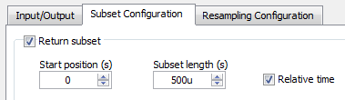
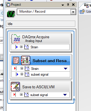
Subset and resampling (http://zone.ni.com/reference/en-XX/help/371268M-01/expresswb/subset_and_resample/) seems to be the most recommended, however I have a few questions about this. I selected a range of subset of 0s to 1s and then choose a resampling of 200 Ms. that seems to be the more manageable sampling frequency, but then I have a problem with the export of the data collected. I get a message that says I can't export to Excel, as the data are 'not continuous' and can only convert to text. However, the text file is not really useful as it breaks down the data in individual games and puts the time in terms of dt. For small sets of data, it seems that it would be possible to manually determine every moment given by point, but I will receive a large number of data sets. I have tried uncheck the "optimize to run once" but still not the same type of data file. What makes a kind of aggrivating, it's in SignalExpress data view tab can display a graph of deformation over time, that I need in Excel.
Another recommendation is to use the 'Statistics' using the collected samples, then changing the number of samples to change the rate. However, I prefer not to use this method because it seems to imply "at x time, average of the latter strain is y" rather than 'x time, strain is there' and I want just the value of the strain at every 0.5 s, 1 s, 1.5 s and so on (although I guess that how that differ from the subset and resample method?).
The last recommendation I found suggested to use an N-sample acquisition, set to read two samples and then set a delay of acquisition of post about 1000 m that would have been a nice solution, but it seems that SignalExpress impossible to compile all the samples to read a log file, that I have seen only two data points when I opened it in Excel.
I'd appreciate any help, thank you.
Hello MAF101,.
I ran your own project and it worked for me. I just used the following values:
It worked very well, I managed to turn on logging. Then, I tried logging information in a txt file using the instructions below:
I got the attached file below using a relative timestamp. It connected two samples per second.
Concerning
Frank R.
-
NEITHER 9237 quarter bridge absolute accuracy
Given a NI 9237 bridge completion Module with NI 9944 accessory Terminal strain gauges and 120 ohms with GF = 2.11, how calculate we precision of strain?
I was told that the absolute accuracy for bridges of quarter is given by
Absolute accuracy = (Gain error * reading) + (error offset * range) + noise + half bridge watchkeeping tolerance tolerance.
Since I'm on the NI 9944, watchkeeping tolerance would be 500 uV/V (given by OR R & D). The tolerance of half bridge is given in the manual OR 9237 being 1.2 mV/V.
(1) it has no value of 'Noise' of entry for bridges on watch in the NI 9237 manual; We use only the sound of half-bridge?
(2) if I use a sample rate of 1,613 kech. / s (the rate guaranteed valid sampling for the NI 9237 module) and my system is always in his 1st year of use, always is my gain error 0.05%? It is worth noting that 0.05% applies to the 50 kech. / s ; If the gain error does not apply to my low sampling frequency, how can I find the error of gain?
(3) if my maximum/minimum deformation measures around 600 EU (microstrains), how can I change my values "Reading" and "Range" in the equation for absolute accuracy above, if they need to be adjusted?
(4) why the absolute accuracy for a quarter-bridge set up does not include the half bridge tolerance?
(5) is the equation for the conversion of precision of voltage precision for quarter of a bridge, of the strain
 , where U is the precision of the voltage given by the equation of absolute accuracy above.
Example of calculation using the values assumed for quarter-bridge:
Error error/gain Offset = 0.05%
Reading distance / = 25 mV/V
Half bridge noise = 1.6 mV/V * 3
Half bridge tolerance = 1.2 mV/V
Tolerance of watchkeeping = 500 uV/V
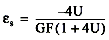
Absolute accuracy = (V/V 0.0005*.025) + (0.0005*.025 V/V) + ((1.6e-6) * 3 V/V) + (1.2e - 3 V/V) + (500-6 V/V) = 25 mV/V +/-1.73 mV/V
Accuracy of the strain =-4(V/Vex) / GF (1 + 4 (V/Vex)) = - 4 * (25 mV/V +/-1.73 mV/V) / (2.11) * (1 + 4 * (25 mV/V +/-1.73 mV/V))
How to simplify this precision of strain to get a reading + / range of precision?
Thanks for any help.
(2) if I use a sample rate of 1,613 kech. / s (the rate guaranteed valid sampling for the NI 9237 module) and my system is always in his 1st year of use, always is my gain error 0.05%? It is worth noting that 0.05% applies to the 50 kech. / s ; If the gain error does not apply to my low sampling frequency, how can I find the error of gain?
This applies at a rate of 50 kech. / s. lower data rate can have up to 0.20% gain additional error reading. This can be found on page 24 the unit operating instructions and specifications document
You get to know how to calculate what percentage of Reading (Gain error) I'd get according to what sampling frequency use? Otherwise, I guess I could use the error of gain of 0.20% in the worst case scenario.
Yes, I so calculate the error of Gain for the worst case scenario (0.2%)
(5) is the equation for the conversion of precision of voltage precision for quarter of a bridge, of the strain
, where U is the precision of the voltage given by the equation of absolute accuracy above.Yes, I think it's the correct equation.
It is more a matter of math - since you will be in the form of a reading + / a range (for example 25 mV/V +/-1.73 mV/V), do you know how I simplify or interpret the accuracy of strain after its replacement by the U-value?
Accuracy of the strain =-4(V/Vex) / GF (1 + 4 (V/Vex)) = - 4 * (25 mV/V +/-1.73 mV/V) / (2.11) * (1 + 4 * (25 mV/V +/-1.73 mV/V))
Just reuse the worst cases to calculate positive and negative values on 1.73mV.
Maybe you are looking for
-
Restore from ios 7.1.2 to 6.1.3
I want to go back to ios 6.1.3. In fact, I use an iphone 4 ios 7.1.2 runnung. I downloaded an image of original paragraph 6.1.3 http://appldnld.apple.com/iOS6.1/091-2610.20130319.Bedr4/iPhone3 , 1_6.1.3_10B329_ Restore.ipsw If I try to restore with i
-
Reliability of the data in the conversion to & from a Variant...
It is possible to convert any data type to a variant, and then turn it back on. In doing so, are there data types who will lose information during the conversion process? If so, why?
-
Windows Media Player cannot play the file
I get the following message appears when you try to listen to a streaming radio station live online. Windows Media Player cannot play the file. A network firewall might prevent the player to open the file by using the UDP transport protocol. If you t
-
What are the ups and downs to get the Windows 3.11 on a pc operating system modern hardwear?
I want to do a monster pc for game twiked using one of the operating system more oldist are there patches that will change a game like world of warcraft, so it can be used to play on it? If so and if the pluse on way the disadvantages I want to inves
-
Windows 7 Ultimate HP ProBook 4530 s, can't see Ethernet card.
I just installed a new OS and I can't get on the Internet to download all the drivers. Apparently, the system doesn't see the Ethernet card. Drivers for this device are not installed. (Code 25) Location PCI Slot 5