NEITHER 9237 Raccordementdu external excitation
Hello
I work with labview 8.6 and using a NI9237 mounted on a chassis.
I use 4 guauges of strain with a voltage of 10V for which I need to connect an external excitation source.
I can't find a way to do this? There are 2 boxes of samll with some connection terminals, but I don't know if I'm doing things.
Also, do I need to change my connections in any way when I use an external excitation source?
Karthik85:
It is not black magic. The constant reading you get is actually the value of mv/V. Which must be multiplied by the corresponding voltage for the mV reading. Read this article and if all goes well he will clarify all black magic.
http://digital.NI.com/public.nsf/allkb/21CA039D8F43C5188625729F005AC2F7
Best,
Santiago
Tags: NI Hardware
Similar Questions
-
NEITHER 9237 external excitement - VeriStand 2013 SP1
The voltage recommended for my pressure is + 10 VDC sensors. I prefer to use external excitation according to the NI 9237 manual, total power to the module is limited to 150 mW, which in my case is "four bridges complete 350 ohm at 3.3 V. (I'll use pressure transducers (4) 350 ohm full bridge). I use scanning for EtherCat engine and the NI 9237 in a chassis 9144 OR connected to a cRIO-9081. For troubleshooting, I have two transducers on a pressure calibrator and another RJ50 connection a NI 9949 escape. If I select "External excitement" and have my power supply of 10 V connected to the bass + EX, EX-connecteur, I get an invalid value for my pressure sensor. It is after the scaling of the calibration value. The gross value is also incorrect. If I let the value "External excitement" but shoot the EX +, EX-connecteur, the EX +, EX-tension (pins 6 & 7) will go to 4.735 V and I'll get a CORRECT pressure reading. If I select an internal 3.3V excitement, I'll get a statement of the correct pressure, but I am a little concerned about the resolution that recommended excitement is + 10 VDC for the pressure transducers. My question is: Why can't I use the external excitement? I have another application with a chassis PXI and EtherCAT and it works OK. I also tried to place a NI 9237 module in the chassis cRIO-9081 and get the same invalid value that I describe above.
You have the latest version of the scanning engine and EtherCAT custom device? On the community page for this custom device, the last listed specifically done bug fix reference to this module. There is also a specific forum for this custom device which may be a good idea to post on as well if you have not already posted here about this problem.
-
With the help of external excitation of load cell 9219
I want to use 9219 to assess the load cells.
Internal excitement for 9219 is not sufficient for my application, this device can be used with an external excitation source?
If Yes is it as simple as cross the bridge of load cell using the external voltage and the output of the bridge on the 9219?
Power max would be approximately 20 mV.
Then the 9237 is probably your best choice. For this voltage, you will need to use an external source.
-
Dear all,
I am a new user of systems OR and I really appreciate and need your help.
I want to connect OR 9237 to RVDT R30A ASSY (the input voltage is 3VRMS). However, I have a load cell connected to my OR who needs 10 v excitation and I need (or have?) to use 10v for all entries. I talked to a guy in MEASSPEC (the company we bought our rvdt of them), and he said, we can use 10v excitement if our signal conditioner can support 30mA. I searched the data sheet, but I could not understand what are the components! Can you clarify for me? NEITHER 9237 can support this control?
I appreciate your help if you introduce me some books or web pages that can help me improve my understanding of the modules and the knowledge of electricity.
Best regards
Bardiya
PS: I'm not sure that I used the right forum for this question or not. I really appreciate your help.
My first question is why you use RVDT? They have a few advantages, but it can be difficult to use without specialized equipment. In case you need a refresher on the RVDT technology, take a look at this. Ideally, if you must use an RVDT for your application, you will use a special signal conditioning and measure RVDT a device like the NI SCXI-1540. These devices, unlike the generic of the analog inputs and output devices proposed below, have specialized circuits to deal with the nuances of the RVDT technology. You can learn more about these things here.
RVDT need an AC source excitation and have an AC output including amplitude and phase varies linearly with the angular displacement. So if you insist on using it in cRIO, since there is no series C LVDT/RVDT/resolver signal conditioning module, you will need two separate modules to use this device with cRIO. One excitation of the AC and the other to measure the voltage AC power.
Module of excitement: the data sheet for this specific RVDT tells ideally to a 3 Vrms, 10 kHz excitation source. Since Vrms for a sine wave is approximately equal to 2.8 * Vpp wave, which means that you need a range of output of about 8.5 v p - p Here are a few cards that could fit this specification: NI 9263, NI 9269, NI 9264 NI 9260.
Measuring module: you can use any module analog input here that has enough channels and can taste a minimum of 20 kech. / s (with a frequency of 10 kHz of excitement, you'll exit will also be 10 kHz.) Meet the criteria of Nyquist sampling to 2 * 10 kHz = 20 kHz sampling frequency). You can find all the analog input C Series modules at least 4 channels of entry here.
In short: use a specific measure RVDT if possible. If this is not possible, explore other displacement measurement technologies that may be easier to use, as an optical encoder. If none of these things are an option, you should be able to use the listed above analog input and output modules to interact with the cRIO RVDT, although it will take significant software development on your part.
-
NEITHER 9237 and SignalExpress
I have a cDAQ-9174 with modules OR 9237 with SignalExpress 2011 for strain gage measurement. After a few problems and doing some research on this forum, I discovered that the minimum sampling frequency for the NI 9237 is 1613 samples/second. However, I need a sample of about 1-5 samples/second rate as my tests will be the order of 4 to 5 hours and record 1613 samples every second will make my too big data file. On the forum, I found these workaround solutions:
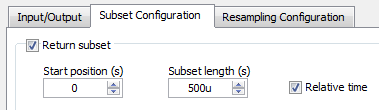
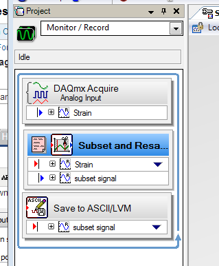
Subset and resampling (http://zone.ni.com/reference/en-XX/help/371268M-01/expresswb/subset_and_resample/) seems to be the most recommended, however I have a few questions about this. I selected a range of subset of 0s to 1s and then choose a resampling of 200 Ms. that seems to be the more manageable sampling frequency, but then I have a problem with the export of the data collected. I get a message that says I can't export to Excel, as the data are 'not continuous' and can only convert to text. However, the text file is not really useful as it breaks down the data in individual games and puts the time in terms of dt. For small sets of data, it seems that it would be possible to manually determine every moment given by point, but I will receive a large number of data sets. I have tried uncheck the "optimize to run once" but still not the same type of data file. What makes a kind of aggrivating, it's in SignalExpress data view tab can display a graph of deformation over time, that I need in Excel.
Another recommendation is to use the 'Statistics' using the collected samples, then changing the number of samples to change the rate. However, I prefer not to use this method because it seems to imply "at x time, average of the latter strain is y" rather than 'x time, strain is there' and I want just the value of the strain at every 0.5 s, 1 s, 1.5 s and so on (although I guess that how that differ from the subset and resample method?).
The last recommendation I found suggested to use an N-sample acquisition, set to read two samples and then set a delay of acquisition of post about 1000 m that would have been a nice solution, but it seems that SignalExpress impossible to compile all the samples to read a log file, that I have seen only two data points when I opened it in Excel.
I'd appreciate any help, thank you.
Hello MAF101,.
I ran your own project and it worked for me. I just used the following values:
It worked very well, I managed to turn on logging. Then, I tried logging information in a txt file using the instructions below:
I got the attached file below using a relative timestamp. It connected two samples per second.
Concerning
Frank R.
-
NEITHER 9237 quarter bridge absolute accuracy
Given a NI 9237 bridge completion Module with NI 9944 accessory Terminal strain gauges and 120 ohms with GF = 2.11, how calculate we precision of strain?
I was told that the absolute accuracy for bridges of quarter is given by
Absolute accuracy = (Gain error * reading) + (error offset * range) + noise + half bridge watchkeeping tolerance tolerance.
Since I'm on the NI 9944, watchkeeping tolerance would be 500 uV/V (given by OR R & D). The tolerance of half bridge is given in the manual OR 9237 being 1.2 mV/V.
(1) it has no value of 'Noise' of entry for bridges on watch in the NI 9237 manual; We use only the sound of half-bridge?
(2) if I use a sample rate of 1,613 kech. / s (the rate guaranteed valid sampling for the NI 9237 module) and my system is always in his 1st year of use, always is my gain error 0.05%? It is worth noting that 0.05% applies to the 50 kech. / s ; If the gain error does not apply to my low sampling frequency, how can I find the error of gain?
(3) if my maximum/minimum deformation measures around 600 EU (microstrains), how can I change my values "Reading" and "Range" in the equation for absolute accuracy above, if they need to be adjusted?
(4) why the absolute accuracy for a quarter-bridge set up does not include the half bridge tolerance?
(5) is the equation for the conversion of precision of voltage precision for quarter of a bridge, of the strain
 , where U is the precision of the voltage given by the equation of absolute accuracy above.
Example of calculation using the values assumed for quarter-bridge:
Error error/gain Offset = 0.05%
Reading distance / = 25 mV/V
Half bridge noise = 1.6 mV/V * 3
Half bridge tolerance = 1.2 mV/V
Tolerance of watchkeeping = 500 uV/V
Absolute accuracy = (V/V 0.0005*.025) + (0.0005*.025 V/V) + ((1.6e-6) * 3 V/V) + (1.2e - 3 V/V) + (500-6 V/V) = 25 mV/V +/-1.73 mV/V
Accuracy of the strain =-4(V/Vex) / GF (1 + 4 (V/Vex)) = - 4 * (25 mV/V +/-1.73 mV/V) / (2.11) * (1 + 4 * (25 mV/V +/-1.73 mV/V))
How to simplify this precision of strain to get a reading + / range of precision?
Thanks for any help.
(2) if I use a sample rate of 1,613 kech. / s (the rate guaranteed valid sampling for the NI 9237 module) and my system is always in his 1st year of use, always is my gain error 0.05%? It is worth noting that 0.05% applies to the 50 kech. / s ; If the gain error does not apply to my low sampling frequency, how can I find the error of gain?
This applies at a rate of 50 kech. / s. lower data rate can have up to 0.20% gain additional error reading. This can be found on page 24 the unit operating instructions and specifications document
You get to know how to calculate what percentage of Reading (Gain error) I'd get according to what sampling frequency use? Otherwise, I guess I could use the error of gain of 0.20% in the worst case scenario.
Yes, I so calculate the error of Gain for the worst case scenario (0.2%)
(5) is the equation for the conversion of precision of voltage precision for quarter of a bridge, of the strain
, where U is the precision of the voltage given by the equation of absolute accuracy above.Yes, I think it's the correct equation.
It is more a matter of math - since you will be in the form of a reading + / a range (for example 25 mV/V +/-1.73 mV/V), do you know how I simplify or interpret the accuracy of strain after its replacement by the U-value?
Accuracy of the strain =-4(V/Vex) / GF (1 + 4 (V/Vex)) = - 4 * (25 mV/V +/-1.73 mV/V) / (2.11) * (1 + 4 * (25 mV/V +/-1.73 mV/V))
Just reuse the worst cases to calculate positive and negative values on 1.73mV.
-
Portable data acquisition support ICP (IEPE) with external excitation source
I work towards the acquisition of a force sensor data Peizoelectric (ICP) with 0 - 5v output and his own excitement of current constant.
Please suggest materials DAQ recommended for these sensors. (We usually use PCI (6229) or the DAQ hardware (9215) compact for static load cells.)
In addition, the LV point of view, is the process to acquire HAVE preamplificatrices such different force ICP sensor of the static load with 0 - 5v output cell?
your thoughts?
-
NEITHER 9237, map of the c series
Yes, the change of measure may mainly be due to the precision.
I think that load cell specifications contain details of precision. It is usually in % of the maximum nominal weight.
Trust that helps
-
Measurment LVDT DC with CompactDAQ
Hello
I am currently working with reading as a result of an LVDT for a project that the present model is the DC LVDT Omega LD620-25
According to the data sheet's model requires a voltage of 10-30 v and a maximum current of 25ma
http://www.Omega.com/pptst/LD620.html
with regard to the available data acquisition modules: the NI 9237 and the 9220 OR by using a module compactDAQ
as the NI9237 has an internal output of 150mW obtained maximum current is 15ma, simply use?
the 9220 OR will be used for the acquisition of data but provides no port of excitement!
as for the solution another I thought using an AC adapter / CC of normal 12Vdc 100ma with a variable pot or a circuit voltage divider to provide the necessary tension
but I have several concerns with respect to the Earth circuit. in this system, I will have two independent reasons!
What will be the best solution to connect the LVDT module to the 9220 OR and provide a source of external excitation?
Thank you
Hello ghattas.ak
Consider the NI 9218. It can provide 12V exictation to ~ 50 mA per channel and read 5 or output 10V DC LVDT. To use this excitement 12V, 9 - 30V power supply must be connected at the Vsup pins. As you said, you can also use the 9220 OR with external excitation. The NI 9237 measuring range of +/-25 mV/V does not cover the 5 or 10 v output sensor you.
See you soon,.
Izzy O.
Product Support Engineer
National Instruments
NI.com/support
-
Accelerometer for several modules in a cRIO
Dear all,
I try to connect my model 805M 1 accelerometer (form is attached) to one of our cRIOs in lab, I think I need some advice because we have two cRIOs and bunch of modules I want to use them instead of buying another module. We have these controllers and modules:
NEITHER cRIO-9073
NEITHER cRIO-9024
NEITHER 9265
NEITHER 9237
NEITHER 9205
NEITHER 9203
I think I can excite (he needs 3 v to 5.5 v) the acceleremoter with for example NI 9237 and read it with NI 9205. Am wrong me or is there another combination that I can use?
I appreciate your help.
Best,
Bardiya
BAK777,
Yes, you can use the NI 9237 module to provide the voltage using a custom voltage customized by excitement and ignore the input data for this task. You can read in the output voltage of your accelerometer on the NI 9205 module.
According to the characteristics of the accelerometer signal, it might be useful to research using an Analyzer of dynamic signals (DSA) module, such as the NI 9234, which is made for the acquisition of accelerometer data applications.
-
CQI RTD sample.vi with simulation device
Hi all
I am student on samples DAQ in labview 2009, I have no DAQ hardware, but I faked 9188 NI and NI 9214 (thermocouple). I want to run 'acq RDT sample.vi' devices with these simulated, but when I run the program it displays error "possible reasons: device to which is attached the sensor doesn't have a source of available internal excitement." Select another device with a source of available internal excitation or provide external excitement. ». However, in the web, it is said that NEITHER 9188 and NI 9214 are available for real-time measurements. What is the problem with that?
What Jacob said, is that the 9214 is not designed to work with the RTD sensors. An RTD is a resistance that changes the value with temperature. A thermocouple produces a voltage proportional to the difference in temperature between the junctions. A measurement system for thermocouples need measure the voltage and often compensates for cold junction temperature. A measurement system for RTD must measure the resistance which is generally to provide a current, and then measure the voltage drop. The 9214 is not a supply for RTD current circuit.
The specificatioons for the 9214, it seems that it will work with the real time operating system.
Lynn
-
Hello
I have a problem with certain measures RTD with the PXI-6289, SC-2345 and SCC-RTD01 setup. I have implemented a DAQmx task in the project, using the following schema:
Name: RTD_Temperatures
HAVE channels 16, 17, 19, 21, 23
RO = 100
PT3851
0 to 250 degrees f.
1mA external excitation
Acquisition mode: 1 sample (on request)
I use a wire 4 PR - 12 RTD of Omega. I've also attached the code what I am about.
My problem is that I don't get the good value of the PXI for RTD temp. I measure the resistance of the probe (109.3 ohms) with a voltage of 0.109V. Using these values, I checked the source of 1mA expected excitement. By raising the resistance of the probe and comparing it to a table of R/T, the temperature should be ~ 75 degrees (who felt all right). However the "temperature", I read of the PXI was 562. I have 5 different channels, and each channel read the same thing when the probe was connected to it. Without a connection to a probe, it was-400 or more. I think it was just due to no connection. I am concerned about the high concentration.
I modeled the code after a thermocouple VI we use already and has proved its worth. Thermocouples connect to the other the 6289 through a SCC68 connector. I thought changing the task to a task of RTD DAQmx would be sufficient. The filter is just a smoothing filter. Any advice or thoughts would be greatly appreciated.
Thank you!
BLUF: When you use the SC2345 and SCC-RTD01, create a new device in MAX under your PXI for the SC2345 and configure the modules you have in each slot of the SC2345. Create a task in MAX (or project), and then select the SC2345 / MOD #: I # (or something similar to that) as the physical read channel.
I finally thought to her last minute yesterday! I have been setting up tasks in MAX under the card/slot DAQmx which had connected SC2345. It seemed logical to me; but my assumption was that the module RTD conditioning the signal and an output value (voltage or what not) to the card and the user just read what is on the card. But I had to in order to operate, the installer places the SC2345 as a new device in MAX under PXI devices. This brought a dialog box configure the SC2345 with the location of the RTD modules. After doing this, when I created a new task, new channel options for each module of the SC2345 appeared. Then you can choose what input of the module (ai0 or ai1) channel to read from. Configure the task to read the SC2345 / MOD #: ai0 instead of saying, PXISlot6/ai0 (where the SC2345 has been actually connected to PXI), gave correct results. I don't know what it means that, insofar as what is doing signal between the module and the PXI, but whatever he does, set up to read from the module worked well.
-
Measurement of the hysteresis with metal plate
Hi all. I have the task of understanding. I want to measure the hysteresis of elastic coupling. To the couple measure I two strain gages on 90 degrees (NI 9237 bridge half, II). After calculation, I now have the couple. In the other hand I measure angle of rotation of the motor with a metal plate with 52 teeth (gear). Angle of rotation I use input digital OR 9401. Hysteresis of bild, now I must on each tooth torque couted. I tried the example Multi - multifunction - Ctr Retrigg a generation sample clock Pulse Train HAVE but still graf give me the straight line. Can someone help me with this? Are there more better example for me, or clips in internet to show me how to do? Thanks before.
This is this case, the problem may be, the data acquisition card cannot rearm the fast enough triger either acquisition takes too long.
In the configuration of the screenshot I see you want to acquire 100 samples at 1 kHz. This means that each acquisition will be at least 100ms which might be too long for your application. NEITHER 9237 supports a maximum rate of 50 kHz, so my first sugestion would be to simply increase the sampling rate and see if it helps.
-
Using signal (+/-10 000 g) accelerometer
Hi all
I use an accelerometer for measurements of vibrations.
The accelerometer is connected to an external excitation device to provide the excitement of the accelerometer (coupler-Kistler). The coupler is then connected with the NI SMU-6361 module which is connected to the NI PXI3-1073 chassis. Based on the gain of 1 and the excitement of voltage of +/-10V, the accelerometer can provide + / 10 000 g. I use assistant DAQ for now to see the signal and then moved to DAQmx. I chose the option of tension instead of tension with excitement and I put the settings +/-10V for max and min values of signal, CSR for Terminal configuration. I also used the option of scaling of the table for the g-10 000 to-10 V and 10 000 g for 10 V. The accelerometer does not seem to work properly as long as the signal does not change. Is it possible for the advice me what goes wrong with the configuration of acceleration it please?
Thank you.
How to set up the chain of coupler/measure:
Your sensor has a sensitivty (let's say it's a constant for a given frequency range) S_ug [mV/g] and you add the coupler with a gain of G_c [V/V = 1]. so you get S_total [mV/g] = S_ug * G_c
The acquisition of your data can read + 5V-(lire les spécifications en détail, généralement qu'ils peuvent lire jusqu'à 5.5V) and the maximum expected acceleration is?
You can always overtemperature or increase the G_c to measure your signals in an optimum range.
You read a voltage u (t) and g (t) = u (t) / S_total. You can do this conversion in your program, or tell MAX / DAQmx for that already in the driver.
You should read the manual of the hitch on the way to configure the gain or sensitivity.
If you measure the pulses, lockout for above 10 kHz signals... you can always use the sensor (up to maybe 40-60 kHz), but some more signal processing is involved in this case and make an FFT on the signal. (or a higher uncertaincy)
If you have the functions of transfer of the probe and the coupler, you can convert your signal in frequency domain, compensate for the functions of transfer and convert bach in time domain, to get a better estinate of your acceleration.
-
Why is the data synchronized out of phase
I'm trying to sync my calendar with a NEITHER-9237 and a NOR-9244 in a C chassis - daq 9178. When I'm not synce synchronization using BD1 (block diagram) it produces this Chart1 XY (data in phase I research). However, to change the data to synchronize acquisition BD2 (block diagram) it produces this Graph2 XY (not the same XY data figure 1).
All the information to fix this error would be appreciated.
Just answer for the most recent message - no time now to carefully dissect any advance information.
First and it of quite a nonfunctional nitpick, but would it not less confusing to put the
initials HAVE config calls * Sub * the encoder configuration calls so that you would not have to cross the streams?
Secondly, it seems that youv'e ' e configured your task of coder to make its sampling based on the
«"" "Sample clock of IT.»»»" Good so far.
The call to perform Nulling incur the subsystem HAVE. I'm assuming that it uses your
other settings for config task (for example, the sampling frequency) in the process, so you start generating
Sample of AI clocks implicitly generating in turn encoder samples.
Sides are the Nulling operation will then stop the sample clock when it's done - it's the
normal behavior for automatic start-up operations DAQmx. So here's what * I * will try:
Perform removal * before * starting the encoder task so that the task of the encoder collect
samples while you null your bridge. As a precaution, call DAQmx Stop for your task to HAVE
just after deletion. * Then * start your task of encoder, and then finally (re) start your HAVE
task.
-Kevin P
Maybe you are looking for
-
Watch iTunes to load on the old iPad today, I noticed that not all of my purchases are there. Example, I bought Eddie Stobards 'Trucking Songs', and some time ago were all there NOW, I have only a 'track' where are the rest iTunes knows that I bought
-
Please help the Apple community (and spreading the word): I was going through the records of e-mail in "on my Mac" (OS X El Capitan 10.11.3 version) and stumbled upon several e-mail folders that were never created. One of them was titled "45 rpm", a
-
Touchpad on my Satellite L50D-B stops working after connecting
Hello I bought L50D-B 12/2014, 2 days ago, it started.After I login I have the touchpad work although all commissioning, but once the start finished it stops. I use a bluetooth mouse, but have used same mouse since I bought the laptop, the printer, t
-
Need to downgrade 3 USB drivers for HP ENVY with Win 8 for Win 7
Downgraded to win 8 to Win 7, everything is fine except that I get the message "USB driver not found" the working USB 2 but 3 USB are not. I need to find pilots who work in this configuration HP ENVY products Desktop H3Y51AA #ABL H9-1387 model number
-
the printer will not acknowledge not receiving new ink cartrages