NEITHER Instrument Simulator model No.: 183913C-01
Hello, I just finished the LabVIEW Core1 online training, that came with the purchase of LabVIEW 2014. I am VERY new in the world of NEITHER. I bought a Simulator Instrument OR model No. 183913C-01 Rev: 1. I am trying to establish communication with this Simulator and not having much luck. I connect the Simulator to my laptop via RS232 to USB Keyspan peripheral, because my laptop is not a serial connection port. It shows to be on Com4. I think I put the dip-switches correctly. I switch 8 G Mode value and GPIB address the value 2 (switch 2 is activated, all the others are off). I searched online for a demonstration, but nothing have mounted. I found a few messages Simulator here but they were not the model I have. I don't know if I should use GPIB or serial connection for this thing. Any help would be greatly appreciated.
Tags: NI Software
Similar Questions
-
corei3 desktop MATLAB simulation model.
Dear Hp hope you are well...
I am a student of BE electric of Mehran University of Engineering and technology (MUTE) Jamshoro.
I do my thessis last year on the theme of the power of high-tech quality analytical laboratory. The High-Tech Lab contains about 16 corei3 desktop PC and a corei7 which is used as a server and these whole parts of society Hp that are recently baught over a period of six months it y a. Sir, I have to simulate the simulation model to combine the entire laboratory, as well as each individual pc performance simulation. Sir, I checked the performance of the PC through the instrument of the ANALYZER of POWER QUALITY, but for a better understanding, it is necessary to simulate a real model of PC.
It is due to help me ask by a MATLAB SIMULINK MODEL OF corei3, desktop pc.
Thanking you...
Sorry, but this is a user-to-peer support forum. HP maintains no official presence here and you receive no official answer to your query here. Please contact HP, in your area, directly for further assistance.
-
Troubleshooting OR Instrument Simulator Version 1
Normal 0
Hello
I recently bought a used Instrument Simulator (I.S.) and I can't get it to function.
When I turn on the power, three LEDS light up: power, ready and listen.
What control input in the VISA test Panel, I get the following error.
VISA: (Hex 0xBFFF0015) timeout expired before the operation is complete.
After getting this error, I check the serial port settings to ensure they are the same. Windows XP, MAX and I.S. are all configured to 9600 baud, hardware flow control, parity, 1 stop bit, 8-bit per character.
After checking that, I unplugged the cable series of the I. S. then I jumper the terminals of cable series DB9 4 to 6, 2 to 3 and 7 to 8. This allows to perform a test of closure as shown here.
http://zone.NI.com/DevZone/CDA/tut/p/ID/3450#2
The result of the loopback test was good. I could send and receive in Hyperterminal, VISA and the base series writing and Read.vi
With all doing just that, I wonder if I bought a bad Instrument Simulator. Is there something I'm missing or it's Junk?
-
Using instrumented hammer model PCB 086D 50 with the NI9234 module and chassis OR cDAQ 9188
Hi all
I need to try to shock with a PCB 086D 50 instrumented hammer hammer. I use the chassis OR cDAQ-9188 with the NI9205 and NI9234 modules. The hammer is connected to the NI9234 and accelerometers are connected to NI9205.
When I test the modules in SignalExpress I get very good results for the dog, but the accelerometers are ok. Also, if I am controlled the hammer OR Max where I have the option to activate the IEPE the result is ok. In SignalExpress, I couldn't find the option to activate IEPE.
I have no experience using software, but I started to learn. Does that mean that I need to program the system for my setup in LabVIEW? Also, the installer of the equipment makes sense, the modules that I plugged on the cDAQ can be used simultaneously? Should I have the additional device in order to use the hammer with cDAQ 9188?
Thank you very much
Emina
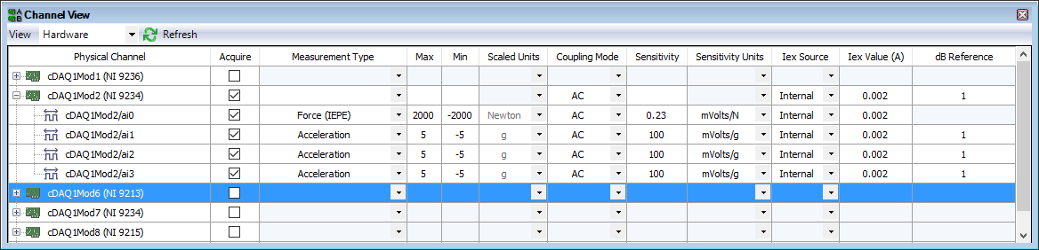
You can enable IEPE in SignalExpress. Here is a configuration for a single power hammer and three accelerometers a 9234-related.
You don't mention the model for accelerometers. They are also the IEPE sensors? If so, have what conditioning of signals you added before the 9205?
The Assistant Sound and Vibration (built on SignalExpress) contains an example of Impact Test. The Sound and Vibration Toolkit comes with a sample project for the impact test. With free evaluation period, go ahead and look at how one of these examples is implementing the configuration and the triggered acquisition.
-
How do I switch parameter (Instrument addr) model of batch test
Hi all
How to pass parameter for the type to step in the model of batch processing?
For example: test taken = 2, the 1st use of USE the instrument (Addr = 10), the use of USE 2nd instrument (Addr = 11), how to pass the addr = 11 for the type of step?
Hi weschen.
When you refer to "pass the parameter for the type to step in the batch processing model", it is you making reference to the call for a subseqeuence and passing a parameter with a SequenceCall in your file of the client's sequence?
Also, you try to pass a value to different address for the parameter of your sous-suite based on the TestSocket index?
-Jeff
-
Attempt to order NI Instrument Simulator to affirm SRQ
Hello
I'm contacting the v2.0 of Simulator OR instrument on a non-Windows using the API of DDK OR-488 platform.
I was not able to get the Simulator to say SRQ with the sequence of commands, as indicated in the simulator of instruments OR manual (* ESE 01; * SRE 20; * OPC)
I am able to send the ' * IDN? "query to each primary address 3 and receive a message to identify each of the simulated devices.
I try to get the DMM to assert SRQ, but devices GPIB simulated will.
AF first I tried investigating different registry settings, but then I see the SRQ light on the Simulator on and turns off and the variable ibsta would show the SRQI bit being set and deleted later when I sent a query command. So finally, I commented on these queries out of my test code after an initial check that the registers have been established as ordered.
They gave me the Simulator instruments NOR without the software Assistant, so I think that the box is in its default mode. However, there is no dip-switches on it except for a switch to toggle the value NRML.
I am able to printf() the ibsta, iberr and return values of the result in the ibcmd(), ibwrt() and ibrd() calls that I do in my test code, so all suggestions about what else in the API OR - 488 DDK in the controls of the Simulator or the simulator of lights that could provide me with more information to debug this problem would be appreciated.
Thank you
PaulHello
After further experimentation, I determined what the problem was. I had previously removed the prefix "0 x" registry values when you set the ESE and SRE registers, otherwise I would get a "command error' in ESR." Although I still consider these values as hex Simulator instruments them interpreted as decimal. So now, when I send the * SRE 32' the simulator of the instrument is what I wait for him.
Which again raises the (minor) issue of why I had problems with the prefix "0 x". I tried ' FORM
 REG HEX' to see if that command, which causes the query to be returned in hexadecimal format, results also influenced the simulator of the analysis of the registry value in the command but still no joy. However, since I have a workaround, I'm moving.
Paul
-
NEITHER Veristand DLL models simultaneous execution
Hi all,
I have to solve that problem is with my VeriStand workspace:
I have a project NIVS with two models of dll (Run/Stop/Pause) execution is monitored in the Versistand workspace by two interface objects user 'Model Control'.
I wonder if it is possible to manage the executions without a click twice, i.e. together with a click of mouse control.
I tried to create a custom user interface object whose controls could / should manage all other objects dll controls in the workspace user interface. then I modified 'Model - model Control.vi' with the addition of a "Call by reference" block to call my user object interface custom controls; but an error occurs when trying to load the object in the workspace. The same problem using a Subvi rather than a reference call.
I hope to be clear.
You have a solution to this problem?
Thank you
Giulio
Hi, Giulio.
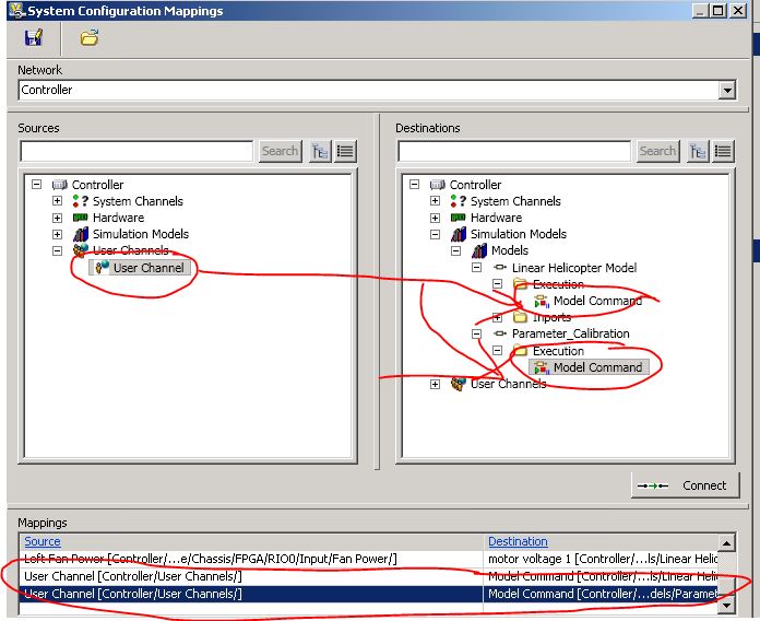
the fastest way to set values of multiple channels (aka "destinations") with a single source channel is the way user combination and maps. It is:
(-) In the system Explorer, create a user called channel model batch start.
(-) Press the button mappings on top and connect the channel the user to both channels of the execution of model, one for each model.
Bind a control of the workspace to the user of the chain)
In this way, you can change the execution mode of several models with a single channel model (and thus a mouse click). You can use a Boolean control if you just want to start/stop the model or an entire control if you want better control each State of execution, which are:
0: start
1: break
2: reset
3: save
4: restoreAn interface object using custom user is honestly an overdose if you just have to set several values at once.
Hope this helps
Concerning
Fabio
-
Hi all. I have an OLD NI instrument Simulator. It is so old, that I'm not still able to use the NI instrument Simulator Wizard. I called for the support and the technician was more useful however, whenever I run the wizard, it opens and alarm that reads "there was an error in location of the simulator of the Instrument OR." Make sure that the equipment is connected to this computer and in Setup mode. I have the 38-page manual that goes to this device. Simulator model number is #183913C-01. I am able to use NI MAX and use VISA Open Test Panel and run commands from there. The challenge is, I have to enter each command, whenever I want to use. I was hoping someone here knows these older model simulators. I posted a question here when I first bought the unit but was not familiar with the operation of it. Any help would be greatly appreciated.
-
How do I MODEL A TANK in LABVIEW
I WANT TOIMPLEMENT a CONTROLLER FOR a TANK of pid. I HERE to KNOW HOW to MODEL GAVE TANK IN LABVIEW Please HELP ME...
If you have the Control Design and Simulation Model, we already have fully functional examples on this subject. Please open the finder example and go in "control and Simulation > monographs > Process Control > Horizontal cylinder and tank with level control. or just open it directly from the file system:
C:\Program NIUninstaller Instruments\LabVIEW 2011\examples\Control and Simulation\Case Studies\Process Control\Horizontal Cylinder\horizontal cylinder non-linear reservoir with level control.vi
Now, notice that it is a "horizontal cylinder tank. If you have a typical tank, you need to change the equation that is solved.
Hope this helps
-
Academic version Simulation Interface Toolkit
Hi, I am a student Brazilian and I use the Labview in my monograph.
I need communication between Labview and Simulink. I have in my computer of 2012 Labview and SIT AcademicVersion installed that came to the DVD of the academic version of Labview 2012. I also have the Matlab R2009b X 32.
It is possible to establish communication using this version of the software.
Sorry for the bad English
ATT,
Victor Barreto
Graduating in control and automation engineering.
OLA Victor,
Como seu modelo e uma transfer language e possible that voce faca using only the LabVIEW e o Module of Simulation of design by & control. Você pode seguir o implementation tutorial on the way deste modulo para understand como fazer isso.
http://zone.NI.com/reference/en-XX/help/371894G-01/TOC17.htmParte este e tutorial help do LabVIEW Control design & Module of Simulation.
http://zone.NI.com/reference/en-XX/help/371894G-01/
UMA outra alternativa e voce converter o modelo mdl você possui para LabVIEW using a Simulation Model Converter dialog box
http://zone.NI.com/reference/en-XX/help/371894G-01/LVSIM/sim_simtrans/
E to você puder use o LabVIEW 2013 you can use model o Interface Toolkit (MIT), than substituiu o SIT e possui uma abordagem but intuitiva.
http://zone.NI.com/reference/en-XX/help/374160A-01/vsmithelp/mit_vsmithelp_boilerplate/
Atenciosamente,
-
The States VS 2011 helps:
************************************
Strap of model execution
Each model run loop running a compiled template for. The number of loops execution model is determined by the number of models specified in system definition file. By iteration, the loop of each model is run performs the following tasks:
- Reads the data sent by the primary control loop and maps those data to the inputs of the model.
- Performs a single step of the model.
- Reads the values of model output and sends this data to the primary control loop.
**************************************
Suppose that:
- I have 3 models such as the output of each model is directed towards the entrance of the next model: model 1 model 2 > model 3
- with channels correspondents mapping such as:
Model1_output <---->Model2_input
Model2_output <---->Model3_input
- The order of execution is set to "parallel."
- Decimation of model is set to 1 for all three.
The three models will run within the same tick PCL "in parallel" in the context of loop PCL, while running in series in the time slot of ticks because of the way the channel map is defined?
THX.
L.
Lol stream mapping does not determine the order of execution. In parallel mode, the three models receive identical entries of the PCL. These entries are based on the previous iteration of the system. The outputs of the model of the iteration (N-1) update the PCL at the beginning of the iteration (N), and these updates are available as inputs of the model during the iteration (N).
In your case:
Check 1
Write A for model 1, model 1 run and written was ' to PCL
Tick 2
Model 2 Gets A' starting from PCL, runs and writes A "to PCL
Tick 3
Model 3 Gets A "PCL, performs and writes A" ' to PCL
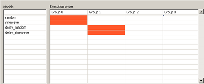
If this is not desirable, you should put the standard models of the category of the order of execution under the Simulation models in System Explorer. This makes the outputs of the model available on other models in the same iteration of the PCL. Note, there is no output model available for the rest of the system until the next iteration of the PCL.
Steve K
-
Is there a model for MCU PIC12F675?
I am currently working on a design that integrates the MCU PIC12F675 of Microchip. I want to be able to simulate this circuit in Multisim, however, there is no included model for her. Is it possible to get this simulation model?
Hello
In Multisim allows only to simulate 8051/8052 and PIC16F84/PIC16F84A. There is no way to add new models of microcontrollers to the database.
Kind regards
-
I have a problem with the rate of a PXI 8109 RT controller model.
I'm running that one model, with simulink and compiled with real-time workshop.
Whatever step size I choose real-time workshop, I see the rate of correct model of the window "Add a simulation model" of Veristand, but when I actually add the template, I still see 100 Hz as a model in the model info window.
What Miss me?
Thank you
Matteo
Hello Matteo,.
It is a known problem with NI VeriStand 2011 which should be fixed in NI VeriStand 2011 SP1. The rate shown is just cosmetic and the model must always turn the rate you specified. To correct the rate displayed, you can click Refresh should update to the specified speed.
-
Reproduction of example of Simulation Interface Toolkit
Hello everyone,
trying to replicate the example provided in the Simulation Interface Toolkit - how-to , I am facing an error with LabVIEW 2009.
I have created a host VI working with the file .mdl Simulink on localhost as Simulation environment that runs smoothly.
And I can't properly compile the file desired .dll (sinewave.dll) with Simulink and nidll.tlc.
But if I want to use a cRio-9024 as time real target FPGA-interface I get the following error when I start the host-VI:
Missing file of Simulation Model
The sinewave.out simulation file could not lie in the projected paths. Please FTP the file manually to your system in real time.
The following planned paths do not contain the simulation model:
C:\ [...] \sinewave_nidll_vxworks_rtw\sinewave.out
C:\ [...] \sinewave_nidll_rtw\sinewave.out>>>
It's the State of deployment resulting:
Initializing...
Calculating dependencies...
The checking for conflicts. This may take some time...
Prepare the items for download. This may take some time...
Deployment NI_FileType.lvlib
Deployment NI_SIT_util.lvlib
Deployment NI_LVConfig.lvlib
Deployment NI_SIT_Replay.lvlib
Deployment XDNodeRunTimeDep.lvlib
Deployment NI_SIT_Data Log.lvlib
Deployment NI_SIT_SITServer.lvlib
Deployment NI_SIT_driversupportVIs.lvlib
Deployment NI_SIT_ClientConnMngr.lvlib
Deployment NI_SIT_sitctls.lvlib
Deployment sinewave_Driver.lvproj
Deployment of NO-Mess-Fix(successfully deployed target settings)
Deployment NI_SIT_Data Log.lvlib:Expand Signal Name.vi (7.85 K)
Number.VI NI_SIT_Data Log.lvlib:Get group deployment (4.46 K)
Deployment of Text.vi "BOLD" (11.92 K)
Deployment whitespace.ctl (2.09 K)
Deploy the value string Value.vi (5.06 K)
Deployment of NI_SIT_Replay.lvlib:Wait for Ack.vi (5.50 K)
Deployment NI_SIT_driversupportVIs.lvlibIT pilot FP Strings.vi (2.31 K)
Deployment NI_SIT_driversupportVIs.lvlibCommand.ctl Server IT (2.09 K)
Deployment NI_SIT_Data Log.lvlib:Enable turn off Item.vi LPG (13.12 K)
Deployment NI_SIT_Data Log.lvliband group probe list is activated (9,54 K) Groups.vi
Deployment NI_SIT_Data Log.lvliband group probe list active record State.vi (7,41 KB)
Deployment NI_SIT_driversupportVIs.lvlibcalendar Src.viNI_SIT_driversupportVIs.lvlib ITIT Timing Src.vi loaded with errors on the target and was closed.
LabVIEW: Unable to load the shared library SIT_TimingInterface.*IT_InitTimingSrc:C on the device target RT.
LabVIEW: Unable to load the shared library SIT_TimingInterface.*IT_GenerateOneTick:C on the device target RT.
LabVIEW: Unable to load the shared library SIT_TimingInterface.*IT_ClearTimingSrc:C on the device target RT.
Deployment of container NO-Mess-Fix
Completed with errors of deployment>>>
Why should I produce a file called sinewave.out? I don't think that I really need.
Can someone tell me please how to use the sinewave.dll properly to make it work on my cRio?
(I don't want to use e/s material and yet, just run the file .dll on the cRio.)
The best help for would be a description step by step from a VI of work using sinewave.mdl inside LabVIEW with ready to use sinewave.dll.
I need to examine any document in order to complete this example?
Thanks for your effort!
Hi Jan,
Yes it s a target VxWorks.
Marco
-
I can't for the life of me get JFETS to work in simulation - I have this circuit to the other on fully and completely closed. It uses a J177, resistance on listed on the data sheet of 300 ohms. Then, when I pass YDS 0V I can wait the tension on the FET to be divided evenly between the FET and resistance. When the door went to 15v Vgs is now positive, closing the FET and the overall voltage is on the FET.
The FET never seems to turns on and the full supply voltage always shows on the display. Why is this?
Hi pgo48,
Unfortunately, the J177 component is a single component of page layout, so it doesn't have a simulation model. Green color code by default for a single component of page layout.
The reason why these components exist is to help the PCB design. Simulation models are provided by the manufacturer, here is a link to a simulation for the J177 model.
http://www.onsemi.com/PowerSolutions/supportDoc.do?type=models&RPN=MMBFJ177L
You download the MMBFJ177LT1G_SP3_Models on the site and use the tutorial below to create the part for her.
https://decibel.NI.com/content/groups/circuit/blog/2011/04/06/component-creation-101
All the best,
Maybe you are looking for
-
The two pc uses Windows 8.1. What I seek is to always have the same information on two PCs: emails, archive, addresbook etc.
-
I have a 21 '' screen. I don't have an 18 "discovers. How to bring back my full review?
I have AOC 21 "monitor. With Windows XP. Only a view 18 ". Does not fill the entire screen
-
How do I rest my password
-
Curson jumps while typing on a web page
Original title: when I type an e-mail, letters or typed numbers fly everywhere place (next line, title,?) instead of the normal path next or sequence.While typing mail on Yahoo, letters flying everywhere instead of the normal path. At any time, the
-
Catalogue crashed, it is possible to use mobile?
My LR catalog crashed, but I still have the Collections in LR mobile. Is it possible to synchronize the mobile to LR LR? To find collections and flags?