NEITHER USB 6008 voltage offset using CSR and measurement of diff.
Hi all
I am currently trying the NI USB 6008 housing and I'm getting problems when reading voltage analog using CSR or differential.
So basically, what I want to measure is a PWM signal (0 to 12V), which is divided by a divisor of tension (by two). But instead of measured 0V and 6V
I am in a position a constant 0.8V and approximately 3V.
On the side of digital data acquisition, I give you on impulses for the SSR... and it works fine.
I connect it that way: http://digital.ni.com/public.nsf/allkb/95CC0CB11D7DF3D18625712E000C4ABD?OpenDocument
Would apreciate any help
Best regards
EDIT: Attached graphics acquired are
What is the impedance of your voltage divider? The input of the USB-6008 impedance is not very high. If the impedance of the partition is large, it could cause the effect you see.
Lynn
Tags: NI Hardware
Similar Questions
-
NEITHER USB-6008 connect to thermocuples and pressure sensors, control valve
I am endevoring to build a gasification plant biomass for bench scale test process control plans. NEITHER USB-6008/6009 will be adapted for use as a data acquisition. I'll take RTDS, thermocouples and pressure sensors. I don't want to use industrial automation controllers. It is also possible to use the channel of analog output for sending signals to a control valve position (using sufficient current/voltage between the two drivers).
(1) OK. I just wanted to be sure that you were aware of the potential dangers.
(2) an RTD is a resistance that has small changes in resistance per degree of temperature change. To measure that you have need of a current source and a sufficient resolution in order to detect small changes. At 25 degrees C a typical RTD is 109,73 ohms and resistance ohms 0.38 per degree changes. If you had 1 my crossing this RTD voltage through it would be 109,7 mV and the voltage change of 0.38 mV by degree.
The resolution of the 6008 on the most sensitive range is 0.49 mV > 1 degree. The accuracy of the 6008 is 1.5 mV typical.
For a Type K thermocouple, voltage at 25 degrees is 1.407 mV and change by degree is 39 µV. Millivolt solving half of the 6008 translates into about 12 degrees.
If you need a source of excitement for RTD and a kind of amplification for thermocouples and RTD before she would make any sense to try to use USB-6008.
(3) I have not used anything except LabVIEW with DAQ devices and drivers. I think DAQmx can be used with MATLAB and other languages.
(4) the 6008 is the low range made by NOR. You will need to go to a more expensive camera or add signals conditioning circuits. Talk to your representative OR assistance in the choice of a suitable device.
Lynn
-
NEITHER USB-6008 can measure an AC voltage
Now I am doing a project, but don't know if DAQ can measure an AC voltage or not, the acquisition of data that we use is USB-6008.
Yes, it can measure AC in the range of +/-10 volts and have a sampling rate of 10kS/s.
Application engineer OR
-
Dear all!
I'm looking for help on the NI USB-6008 case. I'm putting in place 4 K thermocouples using this USB-6008 4-channels. I made an express VI in the Labview 8.5 and I have installed all these 4 channels in this VI. The VI is attached for your review! Come to the problem! I get strange readings of these 4 channels even if I have no thermocouple connected to the terminals with respect to this USB-6008. Please help me and explain what is happening? Why am I getting these strange temperature readings while there is no connected thermocouple?
Greetings to all!
Tajim
Dear all,
I'm sorry for not attaching the screenshot of this configuration! Here, it's this time!
Kind regards!
Tajim
-
NEITHER USB-6008 and Linux Comedi compatibility
Hello!
Could you tell if NI USB-6008 compatible with:
-Driver Linux Comedi
- NI DaqMx Base
If it is compatible, please give me the link for documentation on installing and programming.
Thanks in advance,
Vadim.
Hi Vadim,
What version of DAQmx Base you trying to install? I recommend you to install NI-VISA first, version 4.5, here. Please let me know if this does not work!
-
NEITHER USB 6008 tension problem reading
Hello
I am trying to program a USB-6008 on a mac. When I connect to the input to analog 5V output I get a reading of 3.67volts, while on an osscilascope, I read a 5volts voltage. Is this normal? Need to load resistors? Also, I get the same effect with the release of tensions for the analog output.
Hi Zepp2,
Thanks for your post. The pins are you connect together on your device? Depending on the type of connection you have the wiring may not be quite right.
I found a few documents online which hopefully should help you:
Field of connection for analog signals: http://zone.ni.com/devzone/cda/tut/p/id/3344
USB-6008/6009 Getting incorrect voltage reading: http://digital.ni.com/public.nsf/allkb/95CC0CB11D7DF3D18625712E000C4ABD?OpenDocument
Input analog USB-6008/6009 reads about - 1.4V Offset: http://digital.ni.com/public.nsf/websearch/E687933C5694AB00862570BD00593CA3?OpenDocument
Please let me know if one of them will help out you.
Kind regards
-
Hello
I have a problem with some NI USB 6008 OEM.
They do not work! I have attached to my PC and the light starts flashing, Windows detects new hardware and everything's fine (the same way it usually works with the regular OEM-NIUSB6008 Board, not).
Suddunly led turns OFF, and the jury never come back to life again. I run the MeasurementStudio, and I see the boards with a red cross or without serial number (when they are shown as if they were present in the system).
I bought 10 boards and I don't want to try with anyone, because I don't know what is happening and I don't want to kill them all :-(
We have developed some equipment with regular tips and there is no problem... What is the mystery with the OEM ones?
Help, please.
Thank you!!
Hi Luciano,
Thanks for your response and documentation on the flashing led behavior. It helped me a lot to know that if the led is flashing, it could be because it is not properly initialized.
In fact, I had the 8.1 DAQmx version installed on my PC that worked perfectly well with regular advice to the NI USB-6008 (boxed version).
When I plugged the OEM boards, the system seemed to load the drivers and then a message pops up saying "your device is ready to use", but as you know when I opened MAX he didn't have a serial number, or sometimes, he appeared with a red cross.
So, I downloaded a newer driver: DAQmx 8.8. ... I installed it on my PC (first remove DAQmx8.1) and it worked

So, the problem is solved! The problem was, I think, because of the bad initialization of the device. The problem is solved by installing a DAQmx 8.8 version. It works very well with regular and USB-6008 OEM boards.
-
NEITHER USB-9162 driver works for MAX and SignalExpress, but not for LabView
Hello
I looked for a solution for a while now. According to Web sites OR the NI USB-9162 is compatible with LabView 2012. I installed the last DAQmx. My hardware has been detected and is sensitive to MAX and works very well in LabView Signal Express. But it is not detected in LabView 2012. I searched the forum and not found any solution other then all uninstallation and reinstallation of any. It is quite conssuming time and would rather avoid if possible. Anyone have a solution? I wish I could appreciate.
Tool:
NEITHER USB-9162
NEITHER RIO-9215
Benjamin
I reinstalled everything, and now I can work with it. I can't say that I was wrong on the first time, but now it works very well as well as other bugs that are now set.
Thank you for your answers
-
NEITHER USB-6008 outputs in series to generate 10 V
We wonder if it is possible to connect the AO0 the AO1 as a series voltage source that generates 5 + 5 Volts?
The datasheet is not say, do or not, but he says they are independent.
Worst case being short, one of the outputs short-circuit if the ground is common?
-
USB 6008: problem with using the 5V output
I am a new user of products OR.
I have a USB 6008 and I want to connect the output constant 5v (PIN 31) leg of VCC to a pressure sensor.
My device is connected to the computer, but I get no signal output. Do I have to do something to activate the output or is it constant? If so, why can I not see a signal in the meter?
Thenk you for your help.
Dikla
The 6008 has an amout 5V output limited power available. Make sure that your sensor attracts less then the 200mA who is spec'd for the 6008. In addition and I have to ask, you have the sensor on the ground ground 6008?
-
NEITHER USB 6008 AI acquisition and generation of pulse
Dear users of LabVIEW,
Greetings for everyone. I am a beginner of LabVIEW and I have a problem that I solved partially. I would really appreciate your help and suggestions that I searched for days without a bit of luck. The problem is as follows:
I am the acquisition of tension HAVE (continue) 4 to 8 accelerometers. In the meantime, I send you a digital output signal each time when you click on the sampling frequency (i.e. 1000, 2000, 3000,...) If the sampling rate is 1000). In other words, try to send a signal of output digital (at a frequency n Hz) at intervals of 1 second (depending on the material). To make the digital output signal begins to blink a LED every one second. In addition, I need to write signals (voltage) AI and the LED blink timestamps PC (software) separately. All stages of the above are followed in my .vi program, but the real hardware/software level operations kill my timestamps. In other words each LED flash timestamps are not accurate, when I use LabVIEW measurement file express VI (the difference is not at least to the third decimal). In addition, the timestamp is kinda OK when I disable the file LVM write VI. Onemore thing I've noticed is that physically the LED blinks every second two times, I feel it's because of the shift register and loop delay of a second. Is there a way to control the speed of blinking (i.e. Boolean State must change to every 500ms without delaying the inside while loop).
Results and comments:
LabVIEW 2011 .vi, timestamp of files with or without generator of LVM (express VI) files are all attached. Please note that there is a considerable amount of drift in the consecutive timestamps when the file LVM generator is used, on the other hand there are derivative of 0.001 ms when the file LVM generator does not. The reason for horodateurs PC have is about aligning the various measures or observations or events to global time scale.
Please give me any suggestions or help me do at least accurate to milliseconds in VI of witten. Finally, is there any USB DAQ module relatively inexpensive which allows to send an impulse to directly from channel impulse of output digital channels when the "n" sampling frequency Hz is obtained by level of material which could all be accurate, so that the software timer is completely reduced to a minimum. Although there are very material sophistiated of NOR, but our goal of this project is to build and test the system profitable.
Thank you and I really appreciate your time and effort inavluable. Have a great weekend!
Just change the samples to the constant playback at the entrance of the DAQmx Read.vi from 1000 to 500.
Lynn
-
NEITHER USB 6008 help to order 3 relays.
Hello! I have a DAQ 6008, and I need to control the three relays for the filming of lights, so I scored a VI to activate the relay through three buttons. My problem is that I don't really know what kind of relay that I need. I need something like 5VDC to 230VAC. What do you recommend?
You will need a driver-relay or transistor to provide current to fly this relay.
On a datasheet for the relay, tried google? The part number printed on the side of the relay.
The ULN2003A is a good relay driver. A 2N4400 transistor will do the job too. Both are very easy to connect.
-
NEITHER USB-6343: erratic low frequency 1 counter measures
Dear members,
I'm looking for help with a measure of low frequency counter. I tried to make it work for a week or two, but I keep getting erratic measures. It will read the rpm properly for a second or two and then it will give a ridiculous value on the order of 10,000 times the correct value. I can not get a constant value.
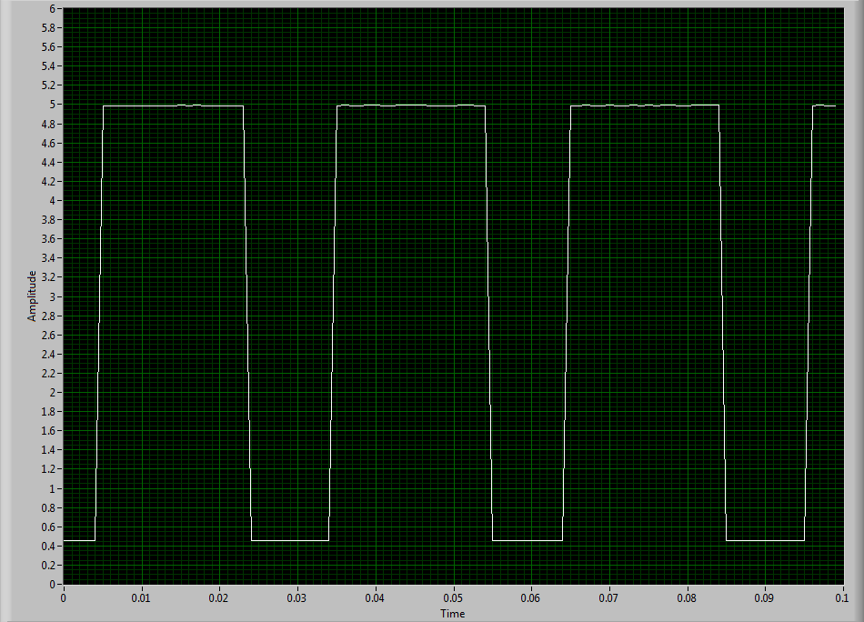
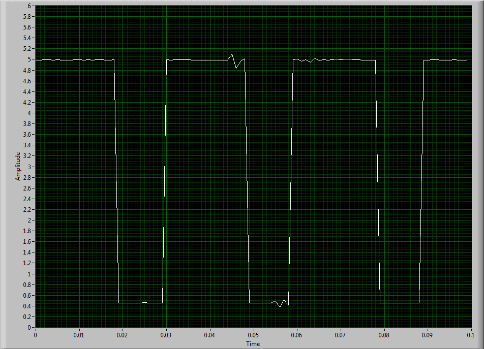
I use a DAQ series X NI USB-6343 multifunction with Geartooth Honeywell GTN1A111 sensor. I enclose a sketch of the wiring configuration. I think that it is correct. Sensor output to the door of the meter.
To try to solve this problem, I hooked the sensor to an analog input channel to make sure that I was getting a TTL signal by sensor. I noticed every once in a while I'd see a glitch of little noise in the signal and I guess that's what is causing my problem with the meter. I inserted two waveforms of the sensor signal (one with the clean signal) and the other with the glitch of noise. My understanding of a TTL signal meter channel will examine LO voltage when it is below 0.8V and HI when it is larger than 3.8V. So I really do not understand why these little glitches could be the cause of the problem because they are well below and above 0.8V and 3.8V, respectively. I think that the noise comes from a frequency converter used to drive the engine. I tried the system as much as possible of the Earth.
I guess I'm looking for another approach. I could potentially use a digital filter to help with noise? The glitch is in fact the problem or I forgot something. The VI in question is attached.
Thanks in advance,
Mike
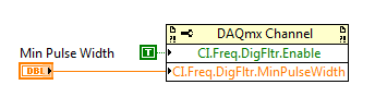
Have you tried to set up a digital filter yet? Obviously the seeds are collected as an additional transition (the method of low frequency counter 1 measure the period and then reverse, so a short glitch would record as a very high frequency).
You can enable the digital filter with the following property node:
Min pulse width is guaranteed pulse past the filter, so it should be low enough for the real signal is guaranteed to pass through (but high enough so that the glitch is always rejected).
Best regards
-
Input/output USB 6008 test failure
OK I am posting this for the third time, but whenever I go back to the home page of the forum, I'm not able to find my post. If by chance I created duplicates than apologies.
IAM in train to test the USB-6008 case I just got and decided to hang the analog of the analog inputs and see using labview VI.the wiring was done as:
http://i284.Photobucket.com/albums/ll5/bigdawg6/USB%206008%20wiring_zpss2b7hql9.jpg
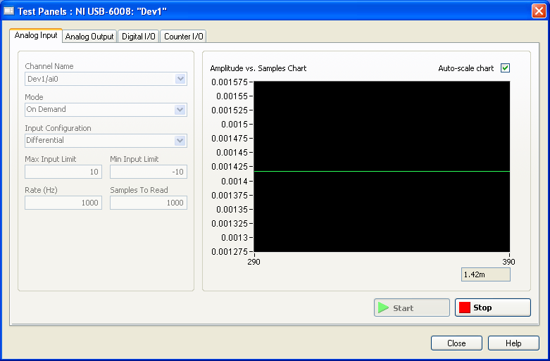
the problem is that the labview VI did nothing, so I go to NI Max and try to see in test panels. But I get 1.4V constantly my same analog input value when I'm changing my analog value:
http://i284.Photobucket.com/albums/ll5/bigdawg6/AIO%20screenshot_zps9beiimbj.PNG
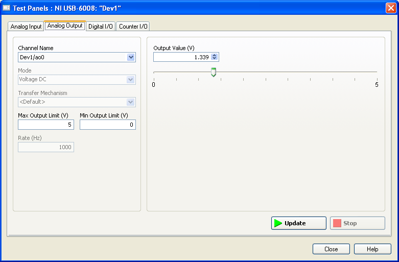
the analog output works very well since I plugged it to my multimeter and I can see the tension that I see on this Panel of test:
http://i284.Photobucket.com/albums/ll5/bigdawg6/AO0%20screenshot_zpsqpei37bw.PNG
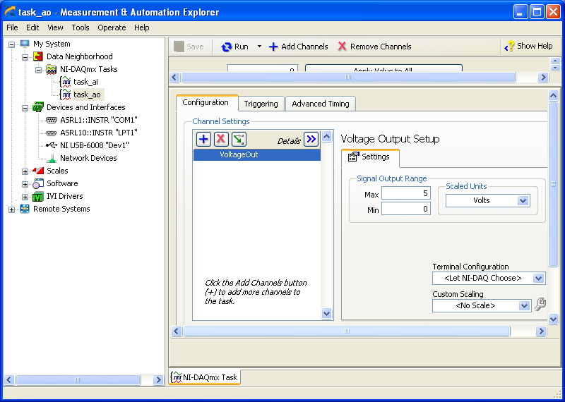
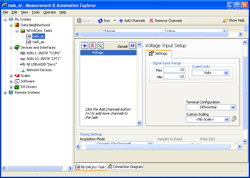
I created an entry/exit of the tasks; screenshots of them are:
http://i284.Photobucket.com/albums/ll5/bigdawg6/task_ao_zpsykmvczew.PNG
http://i284.Photobucket.com/albums/ll5/bigdawg6/task_ai_zpsix5se9yg.PNG
I am quite frustrated with all this since I'm unable to access my actaul draft. I know that 1.4 V value is from the device itself; as in the manual it says 'internal resistance divider can cause the Terminal to float at about 1.4 V when the analog input terminal is configured as a CSR', but the funny thing is that I use it in differential mode so I don't know what to do and any help is appreciated.
BTW, I did a google search and there are other tutorials onlune who seem to do exactly what I do and they seem to work very well; so I don't know what else to do.
Please don't host images on some odd third-party site. Attach them to your message.
I don't understand what you've done. The 6009 can produce only a signal of CSR in order to set up the differential input makes no sense. If you want to measure something different, try a simple battery.
-
Equivalent to USB-6008 with a single output channel?
I would like to integrate the features of the usb-6008 in a small package and really need a release. Is there a suitable product?
Hi Srapoport,
You are looking for something similar, but physically smaller than the box USB-6008 features? If so, I don't think we have any Renault USB which look very similar, if all small.
If, on the other hand, you are looking for something that allows you to develop your own system or enclosure box USB-6008, I would say looking at our OEM hardware. In particular, we have a USB-6008 OEM version, which allows you to integrate into your own system.
http://sine.NI.com/NIPs/CDs/view/p/lang/en/NID/202751
http://sine.NI.com/NIPs/CDs/view/p/lang/en/NID/202750Whatever it is, I would recommend contacting our sales department to learn more about what we have to offer which could meet the requirements of your application. You can find the contact information for this in the 'Purchase and quote' section on our contacts page:
http://www.NI.com/contact-us/
Maybe you are looking for
-
Application (OR-Daq LIC) DLL loading error
Hi all I have an application developed using port, read, write & config of zadvd.lib (lvdaq.dll) which works fine in my XPmachine. In the new machine, I installed labview 7.1 and copy of the application and when the application is loaded, it displays
-
VISA + Serial Communication - need help!
Hello world I have a lot of help with my project of this forum and I'm looking for more . Thank you for taking the time to help. Please bear with my as I ask a LOT of questions. I intend to control a frequency converter using its series terminals and
-
Upload photos from mobile phone to laptop via bluetooth
Original title: bluetooth I have the captain on my laptop I want to download on my lap top. I can pair the phone and the computer via bluetooth, do file on phone on loan, the computer waits - now what? Help, please
-
Update the graphics driver for HP PAVILION 14N201TX
Hi, can someone tell me how to upgrade graphic Drver on my HP PAVILION 14N201TX I use windows 8 64 Bit Enterprise edition
-
Am mit Adeobe Acrobat Pro 10.Vielen Dank!