Equivalent to USB-6008 with a single output channel?
I would like to integrate the features of the usb-6008 in a small package and really need a release. Is there a suitable product?
Hi Srapoport,
You are looking for something similar, but physically smaller than the box USB-6008 features? If so, I don't think we have any Renault USB which look very similar, if all small.
If, on the other hand, you are looking for something that allows you to develop your own system or enclosure box USB-6008, I would say looking at our OEM hardware. In particular, we have a USB-6008 OEM version, which allows you to integrate into your own system.
http://sine.NI.com/NIPs/CDs/view/p/lang/en/NID/202751
http://sine.NI.com/NIPs/CDs/view/p/lang/en/NID/202750
Whatever it is, I would recommend contacting our sales department to learn more about what we have to offer which could meet the requirements of your application. You can find the contact information for this in the 'Purchase and quote' section on our contacts page:
http://www.NI.com/contact-us/
Tags: NI Hardware
Similar Questions
-
Get incremental counter/sound to work along side with action with usb-6008 with labview tia sal22
Get incremental counter/sound to work along the coast with usb-6008 with labview tia sal22
Hi all
I can get this vi to work if they are distinct from the vi but I can't join them together
Example of my error:
If buffers are set to 0 the freq counter increment works, but no sound
If the buffers are set to 1 the audio works fine but is not increment the Freq counter
If the buffers are attached to more 1 clicks and pops are comingThat's what I'm doing:
(1) have the frequency of increment of my internal sound card to a certain level as .01hz a second until he gets to 20 000 hz(2) use my device usb-6008 daq, which is connected to the same machine to measure the voltage at the same time. (I am in a position very low voltages between 1-5volts)
(3) output to a worksheet text file which will show you:
time in seconds, frequency, voltage
0,400.01,21,400.02,2.5
2,400.03,1
I'm a bit confused about how connect the increment and the audio during the measurements with the usb-6008 housing on the same machine
at the same time and in the same VI.Anyone have any ideas? I'm using labview 8.5
TIA sal22Ha ha you have been deceived by a dynamic thread. Insert a convert from Dynamic Data Express VI (Palette to own: Signal handling screw Express) between the daq read and build the array function. Then it won't work. Now the value in the dynamic data is only converted to a numeric value
-
USB 6008 always low digital output
I have a work 6008 usb with a LabVIEW program compiled running on the time 2014 engine run that I use to toggle the relay via the digital ports (open collector). The circuit is such that logic 1 means power off. The code has been run 24/7 for the weeks withouth a problem and all the lines of logic then low and stiff it. The code continued to run and was going well. If you stop, the exit code and restart it works and has been for days. Running Windows 7. Any ideas?
Thank you. I'll give it a shot.
-
using NI USB-6008 with libraries .dll
I am trying to write a program that can run on a computer that does not have the 2 GB of drivers using the included dll. (NationalInstruments.DAQmx.dll, NationalInstruments.Common.dll, NationalInstruments.Common.Native.dll) I have an operational programme that is able to use the outputs and inputs on a computer that has installed the drivers to read, but will not work on a computer that does not install the driver. The driver is an absolute requirment for the program (and the camera) run?
Yes, the driver is necessary to use the DAQ hardware. You may be able to reduce the installation a bit, but I don't know how small you can get.
-
Loss of communications with USB-6008
I have a USB-6008 be used to control a couple of valves with its digital output channels. The digital output channels are a relay that energizes the solenoid valves (valves are 115VAC) switching. The USB device is connected to a USB port on laptop.
The software/hardware was working fine, then some time while it was connected there was a power surge. There was a 2 a fuse on the 115 VAC line that blew.
After this communication surge was no longer able to be implemented with the box USB-6008. Is it possible for a power surge affecting the USB device, even if his power comes from the power supply of 5V USB?
Things I checked so far.
Restart the computer with the USB unplugged and start back up - no connection
Check the Device Manager for the USB device to be present - not visible in the Device Manager
Check MAX for device - does not present as gift
Check the wiring to the son of course drop - no defeated cables
try on different laptops - connection
Connect other USB devices to the laptop USB - another fine feature of devices USB slot
Check the + 5V channel on the USB device and do not read a voltage
Any indication seems to be that, somehow, the USB device has been damaged during this surge? Is there some kind of diagnosis offline, I do without seeing the unit online?
Hello the plough,
It looks like the surge caused a sort of feedback of the valve of your USB device. This USB device is not designed for industrial applications and can easily be damaged in the situation you described. For a USB device with a greater ability to withstand this type of power surge, you should watch the box USB-6525. A better solution would be a CompactDAQ or CompactRIO system with a NI 9401, which is designed to withstand 1 000 Vrms, verified by a 5 s dielectric withstand test.
-
How can I get digital signals (interface UART) with a microcontroller with NI USB-6008?
I have acauired a few analog signals by A/D (3 channels). I put each scanned data on 3 digital output with a microcontroller. I want to see if it is possible to import these digital outputs 3 to a PC via a USB-6008? It's like the connection of the output to the digital input of the USB-6008 and import the 3 channels simultaneously to LabView? Do I need to use some other hardware like USB-8451 and connect the clock of the MCU to USB-8451?
Saraydin,
The digital I/o on the USB-6008 is a software program only, so unless your signals are rather slow, it probably will not work for you. In general, the procedure would be to connect each signal to one of the digital lines on the map and then set up a digital entry into LabVIEW task to read the three channels. If you use a device that has clocked by the digital i/o hardware, you then your input clock signal and use it as the sample for the task clock. Here is a list of USB devices supporting DIO clocked by the hardware. Also, there is an example that comes with LabVIEW, which shows how to do this. You can get to it in LabVIEW by going to help > find examples. When the example Finder window opens, navigate to hardware input and output > DAQmx > digital measures > Cont read dig Chan-Ext Clk.vi.
The 8451 is specifically for I2C and SPI, and would be great if you try to make one of these protocols, but otherwise I would recommend the devices in the list I linked above.
-Christina
-
AO. MaxRate, AO. MinRate, AO. Properties of voltage. RNGs for hardware DAQ USB-6008
Hello
in one of my report, I use the AO. Property of Voltage.Rngs to see if the selected DAQ card takes in charge the application voltage range. This works very well for my PCMCIA card as well as a PCI card. Now run the same VI with a USB-6008 device, this property gives all the return values. In addition, the report of AO.max.rate and AO.min.rate of the '0', the output is-200197 error properties. I use DAQmx as it is supposed to support the same functions for all DAQmx devices. Can someone please tell me what wrong here and how can I get around this?
Best regards
Gabs
AO.min.rate and AO.max.rate are 0 and error-200197 back because the USB-6008 case supports the outputs analog hardware timed. The description of error is "device does not support this property." There is an entrance to the knowledge base for this question.
By selecting 'Use Waveform' uses the synchronization of the sample clock. The waveform data type specifies a delta t, which is used to set the sample clock frequency. It is not supported on the box USB-6008. You shouldn't set your calendar of sample type or explicitly assign the "On Demand".
The DAQmx driver supports hundreds of different devices. Not all combinations of properties are valid for all devices.
-
USB-6008 LABVIEW 8.2. SINGLE CHANNEL WITH DBL INPUT VOLTAGE OUTPUT COMPARISON
I AM WRITING A PROGRAM THAT USES A SIMPLE USB-6008 ANALOG INPUT CHANNEL. I WANT TO READ CONTINUOUSLY THE VOLTAGE FOR 60 SECONDS. I WANT TO COMPARE A TENSION FOR THE PREVIOUS OF THIS SAME CHANNEL VOLTAGE, MAINLY FOR THE PERIOD OF TIME MAX VOLTAGE GIVEN, THEN GET A FINAL VOLTAGE READING. THE OUTPUT OF THE VI IS A DBL. I WANT ONLY TWO TENSIONS OF EXPORT TO EXCEL. TO SAVE TIME, I KNOW HOW TO EXPORT. CAN SOMEONE HELP ME WITH THIS ONE.
VI needs an register shift related to the Max & Min function. The current value would be the entrance is and the entrance of x is the left shift register. The max value gets wired for the shift register to the right. Don't forget to initialize it. The output of the shift register is the max you would write and the value of the DAQmx Read out of the loop of wire will give you the last reading.
Your waiting for 45 seconds makes no sense since you said that you wanted to read continuously. You also said that you wanted to read 60 seconds and all this logic is missing. A simple function of time elapsed, it's all you need.
-
Frequency of maximum output with USB-6008
I have a digital circuit containing 3 exits, 3 inputs digital and analog 1 entry in labview with my USB-6008. When I connect to the entrance (via the DAQ assistant) analog, the output frequency is reduced to a maximum of 27 Hz, but I need 50 Hz. is possible to do?
Ah. You'll need a DAQ better than the 6008, to do.
There is no train generation feature buffering or the pulse on the 6008. The outputs are all timed by the software, you cannot build a table and tell the 6008 in the output array. Out of the 6211 must be able to produce this signal. Series X-series Renault will do what it takes; the USB-6341 is probably your best option.
-
USB 6008: problem with using the 5V output
I am a new user of products OR.
I have a USB 6008 and I want to connect the output constant 5v (PIN 31) leg of VCC to a pressure sensor.
My device is connected to the computer, but I get no signal output. Do I have to do something to activate the output or is it constant? If so, why can I not see a signal in the meter?
Thenk you for your help.
Dikla
The 6008 has an amout 5V output limited power available. Make sure that your sensor attracts less then the 200mA who is spec'd for the 6008. In addition and I have to ask, you have the sensor on the ground ground 6008?
-
Want a ramp of output voltage over time and measure input 2 analog USB-6008
Hello
I want to produce an analog voltage output signal that increases over time with a certain slope, which I'll send in a potentiostat and at the same time I want to read voltage and current (both are represented by a voltage signal) that I want to open a session and ultimately draw from each other. To do this, I have a DAQ USB-6008 system at my disposal.
Creation of the analogue output with a linear ramp signal I was possible using a while loop and a delay time (see attachment). Important here is that I can put the slope of the linear ramp (for example, 10mV/s) and size level to make a smooth inclement. However when I want to measure an analog input signal he's going poorly.
To reduce noise from the influences I want for example to measure 10 values for example within 0.1 second and he averaged (this gives reading should be equal or faster then the wrong caused by the slope and the linear ramp step size.) Example: a slope of 10 mV/s is set with a 10 step size. Each 0.1 s analog output signal amounts to 1 mV. Then I want to read the analog input in this 0.1 s 10 values)
Because I use a timer to create the linear ramp and the analog input is in the same loop, the delay time also affects the analog input and I get an error every time. Separately, in different VI-programs (analog input and output) they work fine but not combined. I searched this forum to find a way to create the ramp in a different way, but because I'm not an experienced labview user I can't find another way.
To book it now a bit more complicated I said I want to measure 2 input analog (one for the voltage of the potentiostat) signals and one for the current (also represented by a voltage signal) and they should be measured more quickly then the bad of the analog signal. I have not yet started with because I couldn't read on channel work.
I hope someone can help me with this problem
An array of index. You want to index the columns for a single channel.
-
Input/output USB 6008 test failure
OK I am posting this for the third time, but whenever I go back to the home page of the forum, I'm not able to find my post. If by chance I created duplicates than apologies.
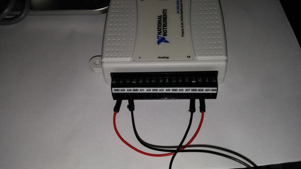
IAM in train to test the USB-6008 case I just got and decided to hang the analog of the analog inputs and see using labview VI.the wiring was done as:
http://i284.Photobucket.com/albums/ll5/bigdawg6/USB%206008%20wiring_zpss2b7hql9.jpg
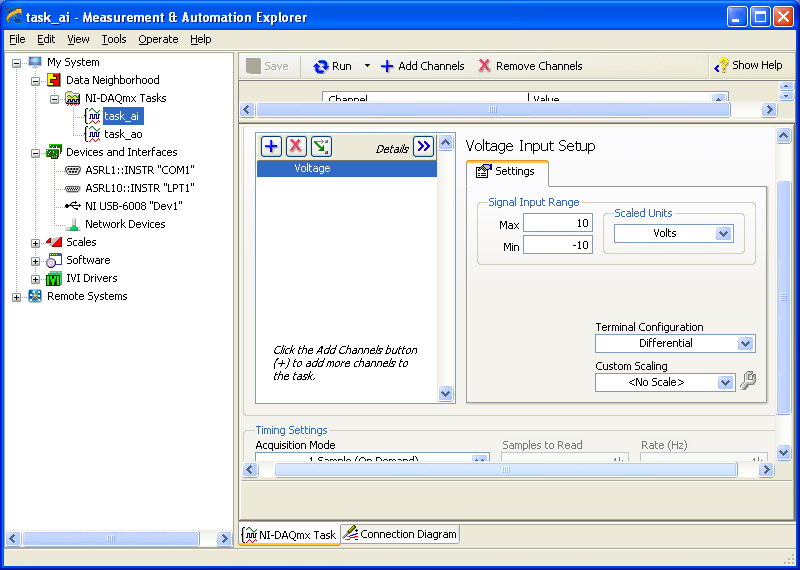
the problem is that the labview VI did nothing, so I go to NI Max and try to see in test panels. But I get 1.4V constantly my same analog input value when I'm changing my analog value:
http://i284.Photobucket.com/albums/ll5/bigdawg6/AIO%20screenshot_zps9beiimbj.PNG
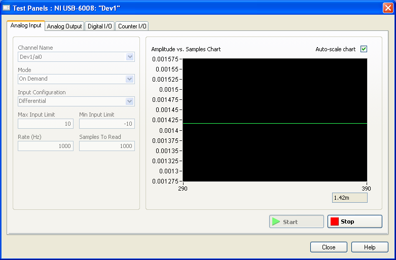
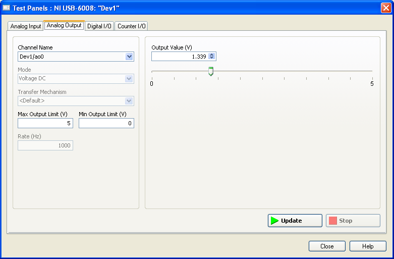
the analog output works very well since I plugged it to my multimeter and I can see the tension that I see on this Panel of test:
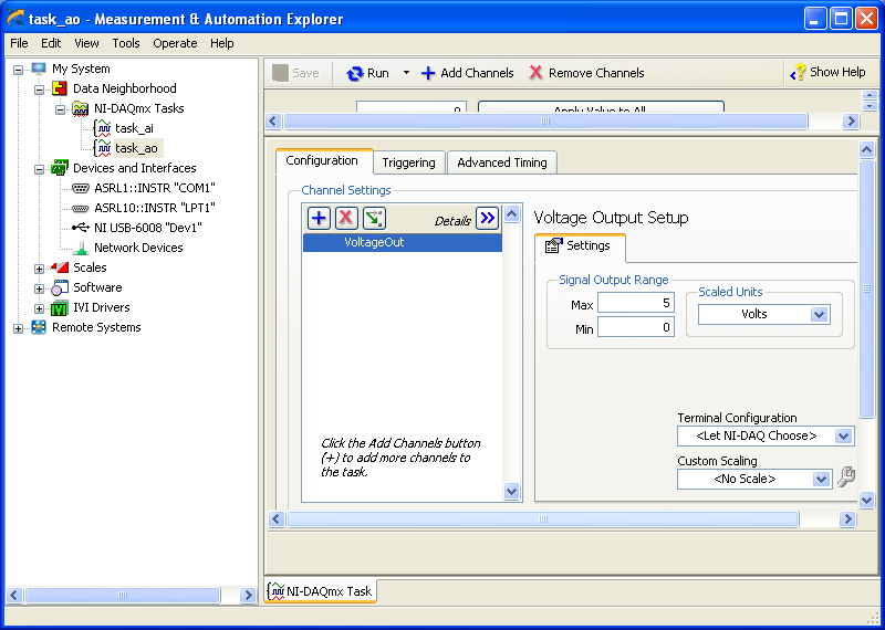
http://i284.Photobucket.com/albums/ll5/bigdawg6/AO0%20screenshot_zpsqpei37bw.PNG
I created an entry/exit of the tasks; screenshots of them are:
http://i284.Photobucket.com/albums/ll5/bigdawg6/task_ao_zpsykmvczew.PNG
http://i284.Photobucket.com/albums/ll5/bigdawg6/task_ai_zpsix5se9yg.PNG
I am quite frustrated with all this since I'm unable to access my actaul draft. I know that 1.4 V value is from the device itself; as in the manual it says 'internal resistance divider can cause the Terminal to float at about 1.4 V when the analog input terminal is configured as a CSR', but the funny thing is that I use it in differential mode so I don't know what to do and any help is appreciated.
BTW, I did a google search and there are other tutorials onlune who seem to do exactly what I do and they seem to work very well; so I don't know what else to do.
Please don't host images on some odd third-party site. Attach them to your message.
I don't understand what you've done. The 6009 can produce only a signal of CSR in order to set up the differential input makes no sense. If you want to measure something different, try a simple battery.
-
USB 6008 digital output signal
I am VERY new to LabView and have been racking my brain trying to get digital output of my USB-6008. All I want is to be able to get a signal of + 5 V of my digital output when I click on a button. This signal opens a valve on a system I see so when it is pressed, it must stay open until I press the new button. It seems simple enough to me, but I'm not too familiar with LabView. Help, please!
Stripling07
You must first take the LabVIEW tutorials and then look at the links to get started with DAQmx .
The simplest program would be with the DAQ Assistant. Drop it on your schema, and then select digital output > digital line. Select the line when the wizard has completed, click OK. Wire a Boolean value in a table to build and the output of which is connected to the data entry. That's all. You can test the output of MAX (Measurement & Automation Explorer) with the test Panel. Do NOT test with your connected tap. Your valve may require more current that can provide the 6008.

-
Hello
I just started using an NI USB-6008 box. At this point, I don't need to fill all the specific tasks other than learning to use the device. I used a fair bit of LabVIEW but never with this kind of material, and I would like to help to understand it please.
In particular, I have attached a VI in which I try to get an analog signal through the USB-6008 and read again (also with the USB-6008 - I wired the pins together). However, I do not understand what is happening when I run this VI. I expect the output a sine signal of 10 Hz for 1 second, 0.1 seconds record and see 1 full cycle of the sine wave. In practice, I read about 10 cycles and constant tension then. Presummably, this means that either the reading continues for more than 0.1 second, otherwise the output signal is more than 10 Hz.
I also tried to use the related calendar DAQmx screws with the output pin to try to adjust the output rate (samples/s) but everything that I've tried return errors. I also tried to open some examples NOR, but these errors returned as well and I still just try things on mine.
Did I miss something obvious here, but any help would be appreciated!
Edit: I had to update this post & attached VI I had made mistakes. The default values on the front panel show what I see after the execution of the VI.
Orbital Hi,
As far as I know, you will need to use the DAQmx Read and VIs write in loops and functions of synchronization to determine data rates you want.
I also did a quick search and found a white paper which you may find useful: http://www.ni.com/white-paper/9541/en/
Kind regards
-
Generate a binary sequence with the NI USB-6008
Hi all
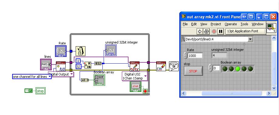
I'm new to LabView and I am trying to generate a binary sequence with a box NI USB-6008. The sequence, I'm currently generate is a counter of 5 bits, i.e. 00000 00001 00010, 00011... 11110, 11111 placing each bit in a different digital IO of the of the 6008 NOR, so that I can use the County as the bits of selection in a decoder/demux.
I managed to simulate the binary sequence and produce a graphical interface, but I have not found how to generate the sequence of bits with the NI 6008.
Totally, I'd appreciate any help you could provide. Thank you very much.
Hi JosephM,
Good Afternooon and I hope your well today.
I just tested the code on a 6008 and also released the above code is very complex - I was for some reason any fixed on using Boolean tables.
Please see the attached code, in LabVIEW 8.6.
Mind you, I have configured the task as a channel for all lines. i.e. digital single I spent, is the task value should apply to all channels selected in the entry. So if you select only port0/Dev8/$line0 for example, the DAQmx driver will examine the LSB of the digital and work so $line0 must be true from the false. It will NOT update all other channels. So when I select line0:4 - it will update the first 5 lines (bits) in digital. As the code generates a number from 0-32 he emotional generates 00000 to 11111.
I hope this finds you well and sorry for the first post!
Maybe you are looking for
-
I can't change the tabs in preferences iMac 10.9.5 Firefox 38
I opened the preferences it is under the general tab in the sidebar by clicking or scrolling is not change seeking to privacy settings
-
How to configure and use canned responses
I don't know how to create a canned response. I'm not sure I know how to contact to a message even if I knew how to create
-
Qosmio X 870: Toshiba Bluetooth installed but Microsoft software stops
I am a Norwegian really sad Panda. my very annoying problem is that I have some time after the release of windows 7 normally lost the toshiba bluetooth stack and the user interface for it and just used start anymoore... First there is when I bought t
-
HP probook 450 g2 i3: battery life
What is the average for my laptop (hp probook 450 g2 i3) if I only watch or browse the internet videos and always connected with wifi stream.
-
From the windows, the following message show:Boot disk failure