Input/output USB 6008 test failure
OK I am posting this for the third time, but whenever I go back to the home page of the forum, I'm not able to find my post. If by chance I created duplicates than apologies.
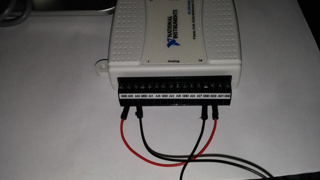
IAM in train to test the USB-6008 case I just got and decided to hang the analog of the analog inputs and see using labview VI.the wiring was done as:
http://i284.Photobucket.com/albums/ll5/bigdawg6/USB%206008%20wiring_zpss2b7hql9.jpg
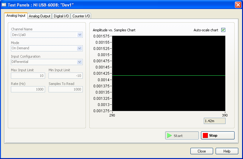
the problem is that the labview VI did nothing, so I go to NI Max and try to see in test panels. But I get 1.4V constantly my same analog input value when I'm changing my analog value:
http://i284.Photobucket.com/albums/ll5/bigdawg6/AIO%20screenshot_zps9beiimbj.PNG
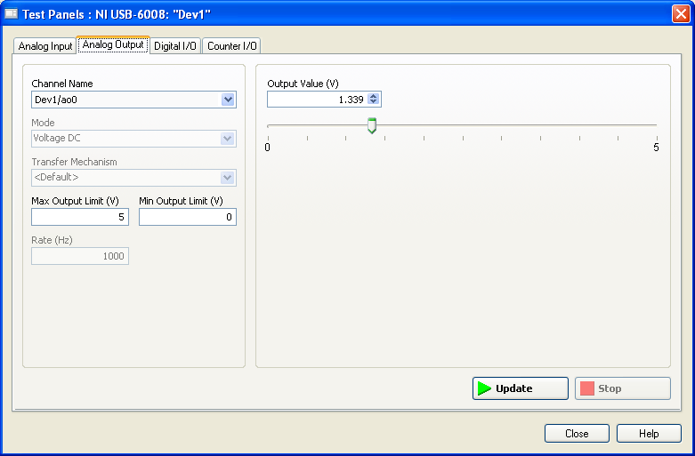
the analog output works very well since I plugged it to my multimeter and I can see the tension that I see on this Panel of test:
http://i284.Photobucket.com/albums/ll5/bigdawg6/AO0%20screenshot_zpsqpei37bw.PNG
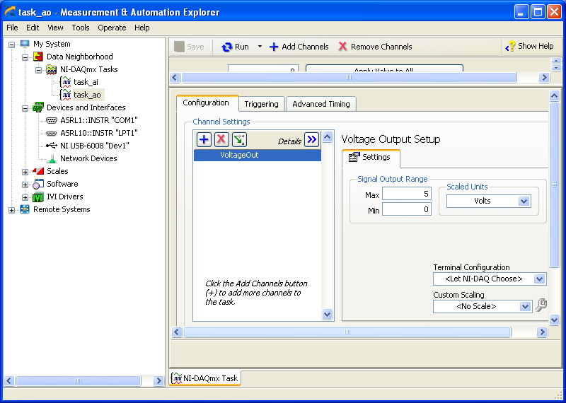
I created an entry/exit of the tasks; screenshots of them are:
http://i284.Photobucket.com/albums/ll5/bigdawg6/task_ao_zpsykmvczew.PNG
http://i284.Photobucket.com/albums/ll5/bigdawg6/task_ai_zpsix5se9yg.PNG
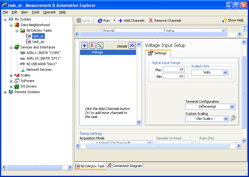
I am quite frustrated with all this since I'm unable to access my actaul draft. I know that 1.4 V value is from the device itself; as in the manual it says 'internal resistance divider can cause the Terminal to float at about 1.4 V when the analog input terminal is configured as a CSR', but the funny thing is that I use it in differential mode so I don't know what to do and any help is appreciated.
BTW, I did a google search and there are other tutorials onlune who seem to do exactly what I do and they seem to work very well; so I don't know what else to do.
Please don't host images on some odd third-party site. Attach them to your message.
I don't understand what you've done. The 6009 can produce only a signal of CSR in order to set up the differential input makes no sense. If you want to measure something different, try a simple battery.
Tags: NI Hardware
Similar Questions
-
Incorrect value for analog output USB-6008. Cannot not out more than 3V
I use USB-6008 analog IO, but the analog output (AO0 or AO1) can go up to 3 - 3.5V. The output can follow accurately the value of 0 to 2, 5V, but then he start the values adjusted trolling and not can not spend you 3.5V exponentially.
The only strange thing the entire circuit is that I connected all patterns (analog source and I/O 5V) between them, but I don't see what affect the output.
Kind regards
ISSOKO
Thanks for the quick reply Ana.
It is not the Council NOR, nor the Council of motorization. Apparently, the interface for motor control (motor spirit C: solutions - cubed.com), load the analog output. A tension following actually isolated op amp output USB-6008 and solved the problem.
Best regards, ISSOKO
-
Hello
I just started using an NI USB-6008 box. At this point, I don't need to fill all the specific tasks other than learning to use the device. I used a fair bit of LabVIEW but never with this kind of material, and I would like to help to understand it please.
In particular, I have attached a VI in which I try to get an analog signal through the USB-6008 and read again (also with the USB-6008 - I wired the pins together). However, I do not understand what is happening when I run this VI. I expect the output a sine signal of 10 Hz for 1 second, 0.1 seconds record and see 1 full cycle of the sine wave. In practice, I read about 10 cycles and constant tension then. Presummably, this means that either the reading continues for more than 0.1 second, otherwise the output signal is more than 10 Hz.
I also tried to use the related calendar DAQmx screws with the output pin to try to adjust the output rate (samples/s) but everything that I've tried return errors. I also tried to open some examples NOR, but these errors returned as well and I still just try things on mine.
Did I miss something obvious here, but any help would be appreciated!
Edit: I had to update this post & attached VI I had made mistakes. The default values on the front panel show what I see after the execution of the VI.
Orbital Hi,
As far as I know, you will need to use the DAQmx Read and VIs write in loops and functions of synchronization to determine data rates you want.
I also did a quick search and found a white paper which you may find useful: http://www.ni.com/white-paper/9541/en/
Kind regards
-
NEITHER USB 6008 tension problem reading
Hello
I am trying to program a USB-6008 on a mac. When I connect to the input to analog 5V output I get a reading of 3.67volts, while on an osscilascope, I read a 5volts voltage. Is this normal? Need to load resistors? Also, I get the same effect with the release of tensions for the analog output.
Hi Zepp2,
Thanks for your post. The pins are you connect together on your device? Depending on the type of connection you have the wiring may not be quite right.
I found a few documents online which hopefully should help you:
Field of connection for analog signals: http://zone.ni.com/devzone/cda/tut/p/id/3344
USB-6008/6009 Getting incorrect voltage reading: http://digital.ni.com/public.nsf/allkb/95CC0CB11D7DF3D18625712E000C4ABD?OpenDocument
Input analog USB-6008/6009 reads about - 1.4V Offset: http://digital.ni.com/public.nsf/websearch/E687933C5694AB00862570BD00593CA3?OpenDocument
Please let me know if one of them will help out you.
Kind regards
-
RMAN > backup of level 0 > ORA-27072: file IO error... Input/output error
Hi, all.
I get the following error messages when executing a level 0 backup. Please help!
====================================================================================================
RMAN-03009: failure of the backup command on the channel of d1 at 2008-11-17 01:08:34
ORA-19502: write error on file ' / NEW_backups/backups/admin/CCPROD/bkups/CCPROD.5313.1.670986008.DB ', blockno 82945 (blocksize = 8192)
ORA-27072: IO file error
Linux-x86_64 error: 5: input/output error
RMAN-03009: failure of the backup command on the channel of d2 at 2008-11-17 01:08:34
ORA-19502: write error on file ' / NEW_backups/backups/admin/CCPROD/bkups/CCPROD.5314.1.670986008.DB ', blockno 84609 (blocksize = 8192)
ORA-27072: IO file error
Linux-x86_64 error: 5: input/output error
Additional information: 4
Additional information: 84609
Additional information:-1
D2 disabled channel, job failed on it will run on another channel
output channel: d1
output channel: d2
output channel: d3
RMAN-00571: ===========================================================
RMAN-00569: = ERROR MESSAGE STACK FOLLOWS =.
RMAN-00571: ===========================================================
RMAN-03009: failure of the backup command on the channel of d3 to 2008-11-17 01:08:34
ORA-19502: write error on file ' / NEW_backups/backups/admin/CCPROD/bkups/CCPROD.5315.1.670986008.DB ', blockno 98433 (blocksize = 8192)
ORA-27072: IO file error
Linux-x86_64 error: 5: input/output error
Additional information: 4
Additional information: 98433
Additional information:-1Since this is a clerical error, I look at the permissions on the target directory and available disk space on the target file system.
-
Want a ramp of output voltage over time and measure input 2 analog USB-6008
Hello
I want to produce an analog voltage output signal that increases over time with a certain slope, which I'll send in a potentiostat and at the same time I want to read voltage and current (both are represented by a voltage signal) that I want to open a session and ultimately draw from each other. To do this, I have a DAQ USB-6008 system at my disposal.
Creation of the analogue output with a linear ramp signal I was possible using a while loop and a delay time (see attachment). Important here is that I can put the slope of the linear ramp (for example, 10mV/s) and size level to make a smooth inclement. However when I want to measure an analog input signal he's going poorly.
To reduce noise from the influences I want for example to measure 10 values for example within 0.1 second and he averaged (this gives reading should be equal or faster then the wrong caused by the slope and the linear ramp step size.) Example: a slope of 10 mV/s is set with a 10 step size. Each 0.1 s analog output signal amounts to 1 mV. Then I want to read the analog input in this 0.1 s 10 values)
Because I use a timer to create the linear ramp and the analog input is in the same loop, the delay time also affects the analog input and I get an error every time. Separately, in different VI-programs (analog input and output) they work fine but not combined. I searched this forum to find a way to create the ramp in a different way, but because I'm not an experienced labview user I can't find another way.
To book it now a bit more complicated I said I want to measure 2 input analog (one for the voltage of the potentiostat) signals and one for the current (also represented by a voltage signal) and they should be measured more quickly then the bad of the analog signal. I have not yet started with because I couldn't read on channel work.
I hope someone can help me with this problem
An array of index. You want to index the columns for a single channel.
-
USB-6008 LABVIEW 8.2. SINGLE CHANNEL WITH DBL INPUT VOLTAGE OUTPUT COMPARISON
I AM WRITING A PROGRAM THAT USES A SIMPLE USB-6008 ANALOG INPUT CHANNEL. I WANT TO READ CONTINUOUSLY THE VOLTAGE FOR 60 SECONDS. I WANT TO COMPARE A TENSION FOR THE PREVIOUS OF THIS SAME CHANNEL VOLTAGE, MAINLY FOR THE PERIOD OF TIME MAX VOLTAGE GIVEN, THEN GET A FINAL VOLTAGE READING. THE OUTPUT OF THE VI IS A DBL. I WANT ONLY TWO TENSIONS OF EXPORT TO EXCEL. TO SAVE TIME, I KNOW HOW TO EXPORT. CAN SOMEONE HELP ME WITH THIS ONE.
VI needs an register shift related to the Max & Min function. The current value would be the entrance is and the entrance of x is the left shift register. The max value gets wired for the shift register to the right. Don't forget to initialize it. The output of the shift register is the max you would write and the value of the DAQmx Read out of the loop of wire will give you the last reading.
Your waiting for 45 seconds makes no sense since you said that you wanted to read continuously. You also said that you wanted to read 60 seconds and all this logic is missing. A simple function of time elapsed, it's all you need.
-
USB 6008 digital output signal
I am VERY new to LabView and have been racking my brain trying to get digital output of my USB-6008. All I want is to be able to get a signal of + 5 V of my digital output when I click on a button. This signal opens a valve on a system I see so when it is pressed, it must stay open until I press the new button. It seems simple enough to me, but I'm not too familiar with LabView. Help, please!
Stripling07
You must first take the LabVIEW tutorials and then look at the links to get started with DAQmx .
The simplest program would be with the DAQ Assistant. Drop it on your schema, and then select digital output > digital line. Select the line when the wizard has completed, click OK. Wire a Boolean value in a table to build and the output of which is connected to the data entry. That's all. You can test the output of MAX (Measurement & Automation Explorer) with the test Panel. Do NOT test with your connected tap. Your valve may require more current that can provide the 6008.

-
Outputs USB digital 6008 volts and the current
Hello
I use 10 V 500 my power supply to the USB-6008 multifunction Board source. (the power is directly related to the last 2 pins of data acquisition). Now, I am a solid state really attract the 18 my and takes 9 V on P0.0. It works fine, but I wonder how long it will work? It's an overload. What is the benfit of using an external power supply and not daw through PC?
I observed that the volt output outputs digital is almost equal to the entrance to power volt. can I continue working with the Volt and current (18mA 9V)? and why? Thank you
Samer
I can't imagine that the external power would contribute to the device. The + 5 line is a power - designed for external devices of power and not as an entry. You're probably stressing many different parts that are designed to operate at 5 volts and a certain amount of current. You really should use an external circuit that accepts entries of 5 volts and amplifies the voltage and current at the levels you will have to drive the relay. Connect the external power supply to the circuit. This is probably at the end to avoid the cancellation of the warranty, but maybe it's not at the end to avoid a total failure of the 6008. If all goes well, a person or who is familiar with the 6008 circuits will display saying that no damage has been done.
-
Frequency of maximum output with USB-6008
I have a digital circuit containing 3 exits, 3 inputs digital and analog 1 entry in labview with my USB-6008. When I connect to the entrance (via the DAQ assistant) analog, the output frequency is reduced to a maximum of 27 Hz, but I need 50 Hz. is possible to do?
Ah. You'll need a DAQ better than the 6008, to do.
There is no train generation feature buffering or the pulse on the 6008. The outputs are all timed by the software, you cannot build a table and tell the 6008 in the output array. Out of the 6211 must be able to produce this signal. Series X-series Renault will do what it takes; the USB-6341 is probably your best option.
-
LabVIEW think my NI USB-6008 has only analog inputs
I am using an NI USB-6008 box to run a route of analog input and analog output.
If I do a constant material DAQmx channel and out the finger tool and pull down... and it offers me 8 analog inputs on Dev1 and nothing else. I've nothing else connected to this computer, but the box USB-6008. A USB-6008 doesn't even have 8 analog input channels.
I'm a bit confused.
-
How stable is the long term outputs analog USB-6008?
The USB-6008 datasheet do not specify the stability long term of the analog inputs and outputs.
I'm looking for stability compared to the ambient temperature and time (several months to a year), mainly for the outputs or the D/A reference voltage.
Is there any information available?
Thank you.
The precision specification takes into account the evolution both because of the temperature and duration (stable). Thus, for the period of a year that we guarantee these specifications, which list you is correct. However, apart from the period of one year since the calibration, this specification may be is more inaccurate.
-
Hello
I have connected a USB-6008 to my computer, but can not read all the output using a multimeter when I run my program.
I went in the measurement and automation explorer, disappeared to the USB6008 device, click on test panels and selected the output voltage. From there, I gave different output voltages and I read all this tension using a multimeter to the USB-6008.
To check if there is something wrong with the pattern-block etc that I install, I connected the 6008 to another computer that is running labview and used the same program. It gives a very good result.
Does anyone have any suggestions as to what can go wrong on the first computer?
Much appreciated,
Paul
If I were in your shoes I download DAQ - mx 8.6.1 (here) on the PC that you are having problems with and give it a go. I don't know why the 6008 would work on a PC and not the other when they have the same configuration. Do you have other devices working on the troubled PC?
-
Lack of external input clocked with USB 6008
I'm a little confused on how to extract digital data without an external clock. I guess that there is a way to do it, or this device would not do any digital input advertising, but I don't understand exactly how that would work. Apparently, my only option is ' we demand. "
I take data frames occurring about every 1 ms with a frequency of 950 kHz clock. I have this completed with a more sophisticated Board using a clock from the data source. We now want to translate this to the USB-6008, so we can use the 6008 OEM like a daughterboard for our data source.
Avoiding him depends on the software you use, the pc, the os, etc. Whenever you want to do a reading of a line, you do a Read DAQmx. Absolutely no correlation with a time given because windows is not even close to deterministic. You may have readings in the low khz range.
-
USB-6008 turning outputs ON and OFF
I'm new to LabVIEW. This is the first time I tried to write a VI that communicates with an external device. Everything I'm doing adjust tensions and put on or off the two analog outputs for a USB-6008. I don't read all the entries or do something with the outputs digital, I want to just turn out analog ON and OFF.
Here's what I have so far.
It does the job of setting that puts the analog output to the USB-6008.
The only thing left to do is to make an executable file. I don't have any idea on how to do it again.
I'm sure a true guru LabVIEWw could have done better, but it does the job.
Maybe you are looking for
-
iPhone 5 in water & off immediately, when is it safe to try to turn it back on?
I gave up my iPhone 5 in the water for maybe a minute and turns off immediately. When is it safe to turn back try or is there something I can do to ensure drying?
-
Tried to change the desktop image and lost all of them.
iPhoto was opened I was looking for an image specific, but also decided that it would be a good idea to multi-task with my iMac and tried to change the image of the desktop at the same time. Apparently, it wasn't the best idea. While seeking photos t
-
Is it possible to add the second cooler to my QOSMIO
I WOULD LIKE TO ASK IF IT IS POSSIBLE TO ADD THIS SECOND COOLER TO MY LAPTOP * (TOSHIBA QOSMIO - X 300 130) BECAUSE MY LAPTOP SHUTSDOWN WHEN I PLAY GAMES...* PIC ALL WHAT I want TO SAY... * http://www.irisvista.com/tech/laptops/Toshiba-Qosmio-X305/bi
-
I need to fix my computer, I got the blue screen of death with the following error message. Registry cannot load the file \systemRoot\system32\config\SOFTWARE "HIVE". I read all the forums on how to solve this problem. I tried all the means which hav
-
Spam of window control Visual Basic
My computer has suddenly started spamming windows visual basic commands. I can't go to any other window because it is constantly open these windows cmd. I tried the Task Manager, who told me that these windows are of 'C:\Windows\Microsoft.NET\Framewo