NEITHER USB-6343 analog and digital grounds
In the manual for the NI USB-6343, it is said that the mass input/output, analog and digital terrestrial are related, but by a small sign. For my application, I am attaching all 3 these grounds to exit the box (I'm tie all areas with physical threads). It is perhaps a silly question, but it's OK to do, correct?
This should be OK unless there are large currents flowing on ground conductors. If you have important currents in the ground, you have other problems that must be resolved before you connect the DAQ hardware.
Lynn
Tags: NI Hardware
Similar Questions
-
Do not connect ANALOG and digital grounds when the annotation to the front at the UB
I'm finding randomly more often when I annotate with impatience to UB analogous and digital patterns do not connect. In addition some power to the IC pin connections are unable to be connected in UB.
Connect to the digital terrestrial analog ground is checked in my properties of Ms.
Is there a reason for this?
Thank you.
Tien Pham offers this solution that worked:
I saw the ground issue in the file you sent and you can fix it by replacing
the digital ground with the one from V12.  On the Spreadsheet View, click
on the "Components" tab, select all the Dgnd symbols, next click the
replace icon on the Spreadsheet to replace all symbols at the same time.
-
analog and digital data synchronization
Hi all
I would like to help with what I seek to accomplish, if you don't mind much.
I'm trying to synchronize the acquisition of analog and digital modes using a common trigger that launches both types of data collection at the same time. What I've done so far, is wasting his time trying different combinations to gather examples of LabVIEW 2011 on the synchronization of data - namely the 'Multi-multifunction-Synch AI lu Dig Chan.vi' and 'Multi-Device Synch-Analog Input-Finite Acq-Analog Start.vi.
I tried to combine the two, because one contains digital and analog, the other contains the trigger for multiple tasks.
I guess I should place the trigger (either digital or analog-eventually I will want to choose) then call the "Get Terminal name with device Prefix.vi. But from there I'm not sure wheter to connect the name of the terminal of the sample clock digital channel or a digital leading edge of the digital chain trigger.
Also, the way it is wired now I get errors at the local terminal name, so I don't know exactly where this terminal must come from.
I try my best, I could use a little help, I have attached my attempt with the examples that I speak to you.
Thank you.
Hi beefcake.
The CtrInternalOutput internal output line is used as sample for your digital output sample clock source clock. If you change the settings for your CO Pulse Time is Dev1 and your digital output is Dev2, you will notice that the name of the product terminal would give Dev2/CtrInternalOutput. So what you get here, it's as well as the digital output device sees his sample clock, instead of the clock itself.
If you just want to use a digital/analog input as your trigger, you should do something more as in the example above. Do you use multiple devices, or are all your lines on the same device? This example is more complicated because it is synchronization of signals on several devices.
Looking at how this VI is wired, you can see that the digital signal triggers the analog signal. You want the analogue signal must be started first, so that when the digital signal triggers the analog task is already running and can trigger immediately. If the digital task started first, it can trigger until the similar task had started, and they do not exactly trigger at the same time.
I hope that clarifies things. Kind regards
-
How to trigger and outputs analog and digital Outout tasks begins on a counter to start?
Hello
I'm trying to synchronize the start of a task outputs analog, a task of digital output and a task of counter. I want to start the counter to serve the master trigger and analog and digital tasks to synchronize his departure.
I guess I need something like:
analogOutputTask.Triggers.StartTrigger.ConfigureDigitalEdgeTrigger ("?", DigitalEdgeStartTriggerEdge.Rising);
digitalOutputTask.Triggers.StartTrigger.ConfigureDigitalEdgeTrigger ("?", DigitalEdgeStartTriggerEdge.Rising);
analogOutputTask.Start (); Slave 1
digitalOutputTask.Start (); slave 2
() counterTask.Start; n / / master
Where? is a string specifying a command source for the beginning of the task of the meter. However, I can't find what this string. Any suggestions?
Thank you!
-Jon
Just FYI, the solution to this problem as well as some other ones is encapsulated in a short example .NET, I created. It is on the Web site of EITHER:
http://decibel.NI.com/content/docs/doc-15500
This project shows how to synchronize all your analogue/digital outputs through tasks and forums in terms of synchronizing Calendar and start clock.
-Jon
-
NEITHER USB-6343: erratic low frequency 1 counter measures
Dear members,
I'm looking for help with a measure of low frequency counter. I tried to make it work for a week or two, but I keep getting erratic measures. It will read the rpm properly for a second or two and then it will give a ridiculous value on the order of 10,000 times the correct value. I can not get a constant value.
I use a DAQ series X NI USB-6343 multifunction with Geartooth Honeywell GTN1A111 sensor. I enclose a sketch of the wiring configuration. I think that it is correct. Sensor output to the door of the meter.
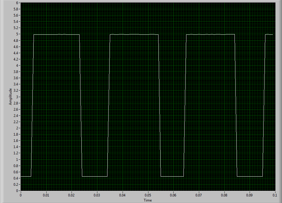
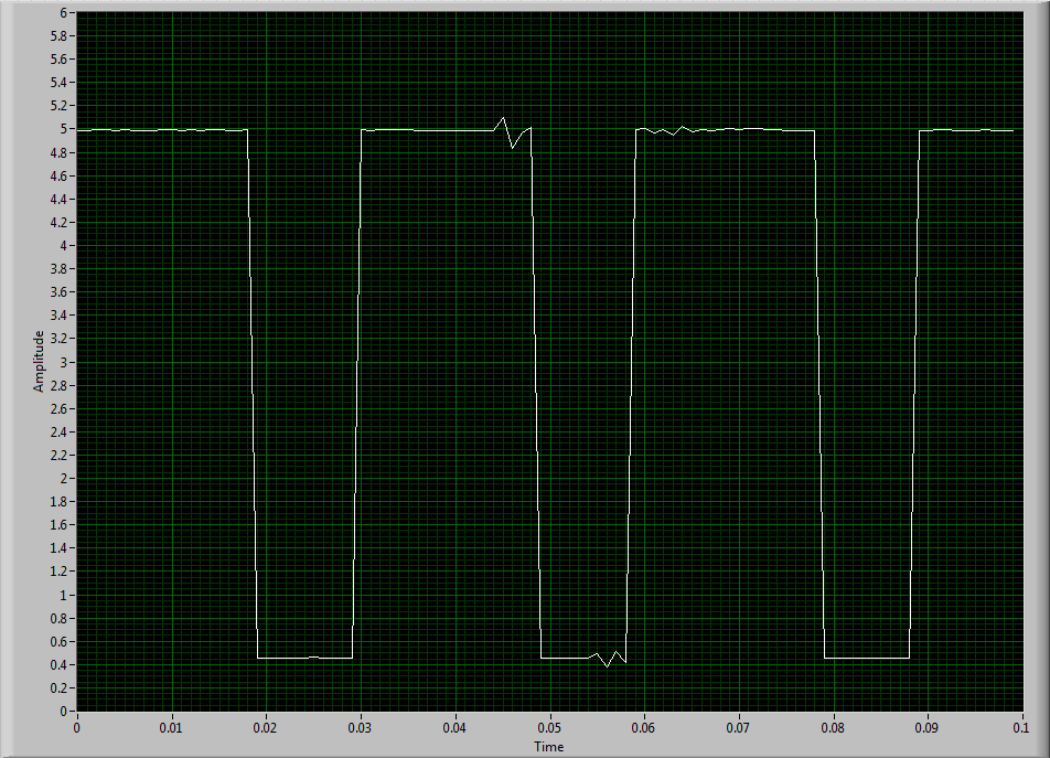
To try to solve this problem, I hooked the sensor to an analog input channel to make sure that I was getting a TTL signal by sensor. I noticed every once in a while I'd see a glitch of little noise in the signal and I guess that's what is causing my problem with the meter. I inserted two waveforms of the sensor signal (one with the clean signal) and the other with the glitch of noise. My understanding of a TTL signal meter channel will examine LO voltage when it is below 0.8V and HI when it is larger than 3.8V. So I really do not understand why these little glitches could be the cause of the problem because they are well below and above 0.8V and 3.8V, respectively. I think that the noise comes from a frequency converter used to drive the engine. I tried the system as much as possible of the Earth.
I guess I'm looking for another approach. I could potentially use a digital filter to help with noise? The glitch is in fact the problem or I forgot something. The VI in question is attached.
Thanks in advance,
Mike
Have you tried to set up a digital filter yet? Obviously the seeds are collected as an additional transition (the method of low frequency counter 1 measure the period and then reverse, so a short glitch would record as a very high frequency).
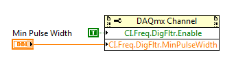
You can enable the digital filter with the following property node:
Min pulse width is guaranteed pulse past the filter, so it should be low enough for the real signal is guaranteed to pass through (but high enough so that the glitch is always rejected).
Best regards
-
Producer consumer with inputs and outputs analog and digital
Hello world
I'm working on a program of control system for some practical test work. Currently, I am working on the data acquisition of the Labview program component. My architecture is consumer-product loops with a what. My system will have analog inputs, outputs, analog inputs and digital outputs. It is not a criticism of time sytem, but I wish that all the acquisition of data to synchronize. I enclose my program because it is at the moment. I have difficulties to get all the data in the since that I have two types of data. In addition, I don't know if I have synced the four sequences of read/write correctly. I would be very happy if someone could take a look at my program and give me some advice. Thanks in advance.
-
Synchronization of analog and digital output with the external sample clock
Hello
First of all sorry for my English, I will try to explain what I want to do.
I want my PCIe-6321 to send two custom signals (modification sawtooths) on a mirror controller. I would also like to generate output with my card at the beginning of each tooth of saw. Everything must be synchronized with an external k-clock signal of 100 kHz. The idea is that whenever the PCI receives a trigger to external clock, it sends two analog output voltages and when he received 1024 clock ticks it will also send a pic of triggering TTL. What I do is first prepare the map and after that in a loop sending and modifing the output values of the two signals and at the same time send a digital signal Boolean in each arch, so when's done it 1024 iterations of the loop I send an event to the digital port. Attached you can see.
The problem is that I don't know how to synchronize both. Can I use the sample clock just to the analog output? I can use sample for the two outputs clock, or do I need to use the output of the meter? If don't know how to use it here.
If I do nothing else bad/wrong, I would be grateful for feedback.
Thanks in advance,
PabloI don't know how but I find the solution. I'm generating more than a positive value (as I was triggered maybe very fast the oscilloscope has been absent there). If I put the sample clock of digital output to use the sampling/ao/Dev1 clock that it doesn't, but if I put to use the same source as the OD (terminal where my external clock is connected), but the trigger to start the DO to be Dev1/ao/StartTrigger this works. I don't really know why, but it does.
Thank you for your patience and your help. I put here the final code.
-
simulateneous of analog and digital triggering
Hello
I have an experience that is very similar to this announcement:
As in the display, I need trigger out of logic AND low frequency (3 Hz) and a signal of high frequency (100 Hz). However, my experience is different because my low-frequency signal is an analog of entry (AI0) and I need experience to trigger off each edge of the signal change high frequency, while the analog input is high. To do this, I created a trigger to HAVE that starts a counter whose state high and low are similar to that of my analog input signal. I then export the output event from the meter to a port (PFI8) and pass this signal and the other signal high frequency through a door AND as in the posting linked above.
So far, everything works. I've included a VI that is just this part.
However, I then connect the output of this gate AND a PFI0 port and use it as a digital triggering to read an AI0, 1 channel. When I perform this final step, my whole system stops working, but gives no error. To troubleshoot, I measured the output of the meter to the port of PFI8 has stopped working and the port of PFI8 remains in the low state. For some reason any when I add the channel HAVE additional (AI0 or AI1, whatever) with digital trigger (PFI0), everything grinds to stop. I have also included the VI for this case.
Any ideas?
Thank you very much!
Hi Jared,
I use indeed a door AND external as described in the thread. Further research actually led me to discover that "you can't have two analog input tasks at the same time" of this thread:
So I had to build a circuit to convert my analog signal into TTL signals (for the release). I then AND'ed the two signals in the same was as described in the thread mentioned above.
-Clinton
-
Fortunately the cRIO merger two time real screws: analog and digital output
Howdy,
I need help with a cRIO code. The purpose of the code is to acquire an analog input from the NI 9234 c series module and be able to send a "signal of pulse" digital camera (first low for some time, t1, then high for some time, t2) from a NI9401. Separately, I wrote the code to perform both tasks. However, when I add the code of RT digital output pulse pulses to analog input RT code, the DMA FIFO overflows because of the way that my digital pulse output code works. Currently, there are two reasons which overflows of the FIFO:
- The digital output code is pending for a while loop (pending "Send Pulse" become a true), the loop I can't empty the buffer FIFO
- The FIFO is not enough, quickly emptied depending on how long the pulse (t1 and t2) times are. The way I keep the pin high or low for a defined period of time is by issuing a sleep command, which blocks the loop I empty the FIFO. (Is there a "best" way to sleep?)
I have attached photos of my codes FPGA and RT. Please give me a suggestion on how to marry my two loops of RT for the use of happy resources! Thank you.
I found a quick way to solve this problem. I moved the timing of the Digital pulse on the FPGA. So whenever I have a Boolean value, the FPGA generates a waveform with the settings I put (a pulse in my case). This works because the FPGA loops run in parallel, I think. That's why, when I run a pending order in the loop of FPGA digital output, it does not prevent the FPGA of analog input loop to run. I have attached a picture of the code.
-
NEITHER USB-6501-24-line digital i/o (OR-DAQ) with LabWindows/CVI 7.0?
Hello
Can I use a recent NI USB-6501-24-line e/s digital (OR-DAQ) with LabWindows/CVI 7.0, although Labwindows/CVI 8.x is required?
Thank you
Dayne
Hello.
In DAQmx Readme, you can see which version of the CVI are supported by the version of current DAQmx. For a map of 6501, 8.7.2 or DAQmx 8.9.5 versions work.
Concerning
-
NEITHER USB 6343 negative DC voltage after power function generator
Hey all,.
I'm having a problem with my DAQ. I'll generate a square wave in Labview with a generator function and that the output to my DAQ. The function exited through the acquisition of data very well; However, when the production is stopped, a negative voltage remains equal to the amplitude ("drawing" below). This happens if I use the express VI DAQAssistant, or manually create the channel, generate the function and the function read/write on the channel. This tension continues even after the VI is finished running. The only way to get rid of it is physically cut the DAQ and turn it back on. Any thoughts on why this might be, or how to fix?
Start VI
____|____|____|____|____|____|
____|____|____|____|____|____| _ _ _ _ _ _ _ _ 0V
____|____|____|____|____|____|____________ - A V
____|____|____|____|____|____|
End VI
Tom
I thought about it. I had to add some more to the clock. I had added a data point in the table of waveform which was written for the acquisition of data because the timer wrote n samples, instead of n + 1

So, to recap: I pulled the table leave the waveform data, inserted a '0' at the end of the wave, reintroduced the data of Y in the form of wave and incremented to the timer of a sample (because I added a sample for waveform data).
-
Analog acquisition and digital simultaneous DAQmx
Hi all
I use the USB-6212 acquisition card to acquire analog and digital inputs. However, I encountered some problems that I don't know how to solve.
All channels (analog and digital input) is independent of one another, but should be acquired at the same time (using the same clock, I think), but I'm not managing to achieve; In addition, I can not put a task so that the digital acquisition is made by "continuous sample" - the error says it is not supported, but I saw this configuration in other examples in this forum.
The only way to get a digital waveform must keep pooling the entry? And, therefore, also in common analog input? Is it not this costly approach from the point of view resources?
Best regards
The decrease of performance will be determined by the speed of your computer and your USB hub.
I think that to get the hardware timing of digital I/o on a USB device, you're going to have to step up to a card in the X series as the 6341, but I'm not sure about this. You can find this specification under the specifications of each product tab. Looking for 'Material' under DIO > Timing.
-
synchronize the outputs digital AND digital NI USB 6343 entry
Hello
I use NI USB 6343 to fly 1 TTL devices. This device can also produce a TTL signal to indicate if the door is opened/closed.
I use digital Bool 1 line 1 Point. I was able to reverse the opening/closing of the door on time. But I would like to synchronize the DI and DO it right.
I tried to throw in the clock aboard, but he failed.
Is it possible to synchronize the DI and DOI onbaord/hardware clock?
Any idea will be great!
Thank you!!
Hello
Synchronization of your tasks of DI and shouldn't be possible with your device. You'll need them timeless has a clock that is usable by both. This information is available in the X series user manual
http://www.NI.com/PDF/manuals/370784f.PDF
PG 6-9 and 6-13You can also find information and examples of synchronization of the various tasks in the article below.
http://www.NI.com/product-documentation/4322/en/Good luck
Eric
-
NEITHER USB-6210 - the analog ground-sharing?
Dear gentlemen/ladies,
I use NI USB-6210 Council and I have four different devices that I need to join in. The problem is that I have to measure all these four analog signals in LabView with the referenced Single-End Mode, which means that I have four different pins to connect in the same slot of analog ground.
So, I would appreciate ideas on how to do it. Is it possible to create more analog grounds by software, for example? Or is there an electric simple component that I can use easily share location on the ground for several pins without causing interference to signals?
I thank very you much for your response, already in advance.
(My apologies if this forum was not one to correct for this post).
Hi Stephanie,.
You can't create more analog designs. On other devices, there are several Earth pins, but they are connected all in-house.
You simply link them all to pin GND AI because it is what it is.
I hope this helps.
Best regards
-
NEITHER USB 6008 voltage offset using CSR and measurement of diff.
Hi all
I am currently trying the NI USB 6008 housing and I'm getting problems when reading voltage analog using CSR or differential.
So basically, what I want to measure is a PWM signal (0 to 12V), which is divided by a divisor of tension (by two). But instead of measured 0V and 6V
I am in a position a constant 0.8V and approximately 3V.
On the side of digital data acquisition, I give you on impulses for the SSR... and it works fine.
I connect it that way: http://digital.ni.com/public.nsf/allkb/95CC0CB11D7DF3D18625712E000C4ABD?OpenDocument
Would apreciate any help
Best regards
EDIT: Attached graphics acquired are
What is the impedance of your voltage divider? The input of the USB-6008 impedance is not very high. If the impedance of the partition is large, it could cause the effect you see.
Lynn
Maybe you are looking for
-
Satellite M40x-148: where can I get the recovery disk
I need a recovery CD for my satellite m40x 148.Is there someone who could help? Were make a copy? A big thank you to anyone with a solution
-
Synchronization of entry OR XNET
I have a more general question. I'm new on CAN interface and I just try to understend better functioanlity of NOR-XNET entry vi. MY main problem is that when I ran vi by itself, it worked very well. Read all images sent my MCU. When I put the same vi
-
problem error code 0 x 80041321 system restore
System Restore has not been activated in my PC when I try to a specific partition pops up this message:"coud not scheduled task for the following reason:This task image is damaged or has been tampered with. (0 x 80041321)"
-
Need help saving the computer to paste data in Vista
I want to back up my computer to a data key. I followed the instructions until I got to the bit where I need to plug in the stick and two ports, it came on J: /. How to locate the E: / drive? Thank you. Carol * original title - E: / drive - how can
-
BlackBerry smartphones are in need of help on the BB 8100
ist of all i say sorry to you because of my bad lang. :( i want to know about blackberry i have blackberry 8100 and i use a pay as you go sim on it because i can not afford monthly packages on it :) and in my blackberry 4.2v. is install tell me full