NI USB-7855R AO maximum control current
Hello!
I'm looking for the maximum intensity on the USB-7855R NI AO.
In the http://www.ni.com/pdf/manuals/375943a.pdf user manual
There is "Minimum current ± 2.5 drive my ' on page 6, is it error (maximum)?
This value for 1 independent channel or maximum load on all the outputs?
Thank you very much!
Hajar,
An update, you can consider a maximum since the unit can be used with down currents and the value represents the current driver per channel and is not an aggregate.
Tags: NI Hardware
Similar Questions
-
Maximum nominal current of the + 5V terminal in PXI-7813R
Hello
I'm a little confused on the maximum nominal current of the + 5V terminal of PXI-7813R in 'NI R Series multifunction RIO specifications '. I understand that there are four connectors for PXI-7813R and each connector has two terminals of 5V +. If I use this + 5V to power my external circuit, what is the maximum current that can be supplied by each terminal?
Thank you
Gwenaëlle
I got your point, in this case I can do separately.
Thank you
Gwenaëlle
-
USB-7855R DIO output different waveform of the seized wave
Hello.
I use usb-7855r.
I see the exact waveform that I entered in usb-7855r. However I m do not receive the same waveform. The frequency is the same, but the voltage level is different. I'm suspecting the logical level of the device.
In the user manual or the specs of the device, it seems that I can change the logical family but I don't know how.
http://www.NI.com/PDF/manuals/375943a.PDF
Does anyone know how to change the level of logic for this device?
Hey Buddy,
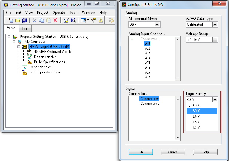
You want to right click on the Target FPGA and click Configuration of change...
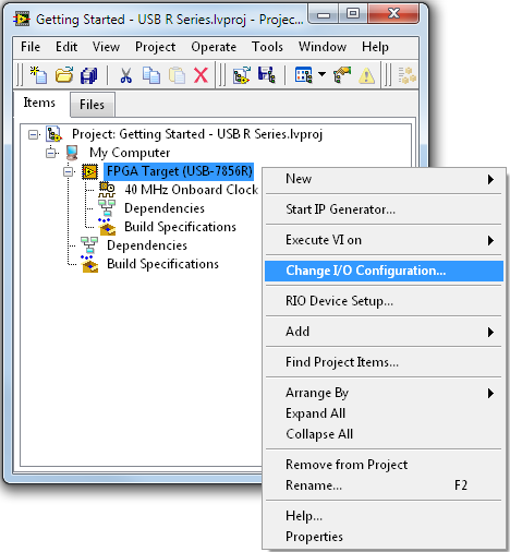
Then, you can set the logic levels.
More details in the help and in this tutorial:
Configuration dialog of e/s series R - OR-RIO 14.0 software help
http://zone.NI.com/reference/en-XX/help/373197D-01/target2devicehelp/configio_dialog/OR R series for USB getting started part 2: Advanced
http://www.NI.com/Tutorial/14837/en/ -
How to build the current controlled current source
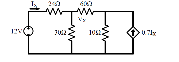
I want to check my solution using multisim, however, I don't know how to build a circuit containing the current controlled current source. Hope someone can help me. Thanks in advance
.
The current direction must be placed between the the + 12V and 24 ohms resistance.
I just made the circuit and if you make the change, you will see that you are right in your calculation.
-
Hello
I had a (LDM) control on my vi which may not exceed the value 0.1. Is it possible to do?
I think it's a pretty easy question, but I couldn't find the answer to it.
See you soon
step is maybe 0.00000001!
-
PowerEdge 2900 - size USB drive external Maximum
Hello
I inherited the responsibility for a Poweredge 2900 server last year. Recently, asked me to mount a NTFS 5 TB external USB drive.
This failed with the following message is displayed:
$ mount/mnt/external_usb_3
Cannot read the last sector (1220940596): invalid argument
TIPS: The volume is a RAID/LDM, but it was not yet, the installer
or it was not setup correctly (for example by not using not not mdadm - build...).
or a bad device tries to be mounted,
or the partition table is corrupt (partition is smaller than NTFS).
or the NTFS boot sector is corrupt (size NTFS is not valid).
Failed to mount ' / dev/sdf1 ': invalid argument
The device "/ dev/sdf1 ' is not a valid NTFS partition.
Maybe you selected the wrong device? Or the entire disk instead of one
partition (/ dev/hda, not/dev/hda1)? Or vice versa?I know the Poweredge 2900 has a limit of drive HARD internal 2 TB because of the PERC5 / i controller. Is this also true for external USB drives? Or is this another limitation HW or OS? I was reading the documentation and found no (or too looked) the answer.
Is it possible to mount a drive of this size of form/repartitioning fitness?
Thank you
Brendan
I don't think that USB would have this type of prescription, unless there was a problem of driver forbidding him. Material, I would say 'no '.
-
OR USB-6009 can produce the constant current source/sink?
Hi all
I have a card NI USB DAQ to 6009. I need a battery for constant (charge/discharge current<1mA) and="" simultaneously="" monitor="" its="">
I was wondering if I can use USB-6009 of output constant source/sink of charge/discharge current the battery? I've seen a few threads that says 6009 impossible to output constant son of currents, but other says we can use the digital output to provide the current, but it was not only described how.
Thank you.
All the outputs of the USB-6009 case are sources of tension and all have current limits low. There is no way to generate outputs current controlled directly from this device.
What I would do (and have done) is to build circuits of external current source/sink with an op amp or a transistor and allows you to enable or disable a digital output of the USB-6009. If the current must be adjustable, use an op amp circuit that takes an input of the analog output of the USB-6009 voltage to set the current. Use an analog input channel to monitor the battery voltage.
Lynn
-
FPGA - OR USB-generation analog 7855R
Hello.
In a project, I chose NEITHER-USB-7855R for a project for the generation of the analog output.
According to the datasheet, 7855 have 1us update time in 16 bits Resoulation.
I'm confuss always update 1. Please corrent if I'm wrong. the time of transition for 1V at 1.2V (1.2V as algo), will be 1?
Data sheet: http://www.ni.com/pdf/manuals/375943a.pdf
Waiting for the answer.
Yes, a sampling frequency of 1 MHz means that the time between samples is 1us.
-
Ive got an acquisition of data USB-6211 (and LabView 2009) and Im trying to get the output (5v) device to run a relay on and outside. IM using a tutorial I found on Internet to make the diagram Labview (http://www.pages.drexel.edu/~pyo22/mem639/lab-usb6211DigitalInputOutput/lab-usbDigitalInputOutput082...) and the circuit is simple. I tried to run the DAQ Assistant to test if my output was working, and it is not. I'm not sure if my connections for data acquisition are correct or not. Any help would be useful.
Thank you.
Hello NT_Mech,
Indeed, it is possible that you do not drive enough current for the relay. You can check the specifications of your USB-6211 and see that the digital line will result in a maximum of 16mA. That being said, your relay control current that is needed, you may need to run the two outputs in parallel to offer twice more common provided. Recently, I drove a Soviet Socialist Republic of a Luminary Micro Prototype Board that did not provide enough current as well. In the case of the tat, I was driving the relay by running two lines in parallel.
You can always simplify the software side of things by opening the measurement and Automation Explorer (MAX) and right click on your device and select test panels. "" ' Start ' programs ' National Instruments ' Measurement & Automation then expand devices and Interfaces. Right-click and select Test panels. You can then configure a digital output for your USB-6211 and toggle On / Off and check out.
Best,
-
Satellite s3000-514 - need info on USB power output?
Hello
Please can someone confirm the output power of the USB ports on the s3000-514? (E.g. 500mA?)
I intend to buy an external USB drive requiring 1000mA of power USB to work.
Kind regards.
WajidUK.
I remember that USB 1.0 specifications are 150 USB 2.0 and for mAh 500 mAh.
A laptop usually provides enough power for an external 2.5 "HARD drive, but not for a 3.5" external HARD drive. Disks 3.5 "are equipped with an additional power supply.
Some USB hubs offer a power outlet in order to increase the maximum current available on each port (i.e. If you connect 2 external HARD drive or a HARD drive on a 2.5 USB1.0 port ")Make sure you buy a 'box' that comes with an external power supply or is less with a second USB cable to connect a second USB port available just for more power.
Remember that external hard drives draw a LOT of energy out of the laptop that runs on batteries... In order to choose the correct POWER option than the second cable.
BTW, the USB port is protected for current requirements extended... it will just hang your PC, stop, or simply not work at all (you'll notice the disk HARD drives which will be very low on disk).
I hope I could help
Concerning
electroch@in
-
DAQ USB 6363 - generate digital data series through the single DIO line
Hello
I'm new with Labview, currently, I bought NI DAQ USB 6363 for generating control signals and signals analog accquire. I would like to send digital data series through one of the digital IOs with throughput of 30 kbps. Please see the attachment for the data frame. Could someone comment the feasibility of this? Y at - it codes for the example that I can refer to? Most of the examples I've looked at so far deals to generate several line instead of 1 single line. How can I achieve this?
Thank you
Diem
Hey diem.
After looking on your code, I understand what you were trying to do. Here's how I'd do. Usually we do not write code to clients, but you peaked my curiosity of! I hope this helps. Good luck!
~ kgarrett
-
The control of several Instruments: read parameter and continuous dynamic update
Hello
I'm trying to control three instruments using LabVIEW. My DC power and generating function are connected to the computer with a GPIB/ENET 1000 while my scope is connected via the USB port. I am currently having the scope to take a reading for each iteration of the while loop and have the event handler if there are changes to the power settings. I went by respective examples of the instrument and came with the attached VI. I wondered for some time on an installation where you connect continuously and are able to modify settings dynamically; It's my first crack at it.
The idea is to expand this VI by logging the reads in a text file, by automating a sweep from 1 K - 1 MHz and taking averages of this sweep to chart in Excel. For now, I need to get down the basic and I'm constantly freezes when I run the VI. Sometimes it runs without problem, but begins to freeze when I try to set the DC supply voltage and other times it freezes right from the start. I wonder if it has to do with the placement of the read scope; before and after the handler but I can't test the theory now that I'm away from the laboratory.
Would appreciate any advice you can give,
Yusif Nurizade
Yusif,
Yes, the steps could be taken in a parallel loop. If this loop will be completely independent (don't share data or control with the other loop), it should be simple. If you do not need to pass data between the loops, you might well be better to learn the architecture of producer/consumer because youwould has essentially re - invent.
Lynn
-
How of current analog output more than 2mA
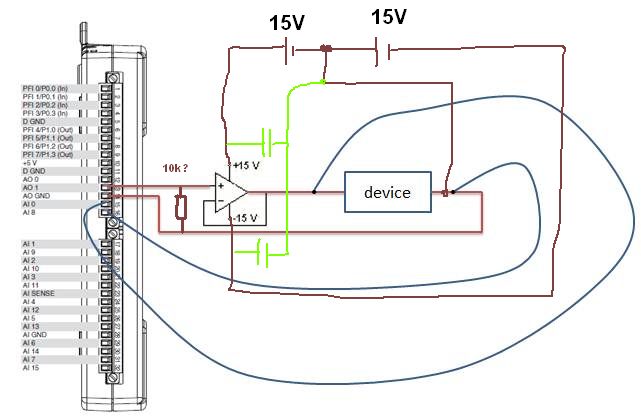
Hi, I have designed a simple PID loop to control the input of a device voltage. My camera has an Ohm resistance. I found that being controlled input voltage may not exceed 0.6V, then I realized that the maximum output current is my 6211 NI DAQ 2mA. But I really need more 2mA (Max is 10mA). I tried to use a voltage follower because it has high impedance imput and low output impedance, but it does not work. Could someone tell me a method to solve the problem?
Thank you.
CJL
100nF caps | with 10µF,.
R optional...
What OP do you currently use?
Without this connection GND current can flow
 so you will stick to 0.6V as without a driver.
 -
a7r USB and wireless tethering
I want to record to the sd card so that attached to my laptop closed hearing and also
the ability to use my Camranger in the same way I use my Canon 5dmk3 via USBWe do not currently have updates that will add this feature. I will forward your comments to our team of control engineering.
-
The charge amplifier power adapter USB
I come from the QX30 and it uses a USB cable to charge the battery, but on my vacation I rarely takes a computer. Thereore, I use a USB adapter to plug into the wall and I wonder if the amplifier of importance at all. You can get them in 1AMP or 2.1AMP, etc and I normally like the amps higher for faster loading and no problem using an amp to 2 + a with Sony battery/camera?
Hi checkyourmirror,
Here are the details based on the specifications of this Cybershot:
- Maximum load current is 0.9 Amp
- The maximum charge voltage is DC V 4.2
If my post answered your question, please mark it as "accept as a Solution.
Thanks, Dave
Maybe you are looking for
-
Thunderbird works on a new 10 HP windows machine?
I just bought a new laptop HP 10 Home Windows. The Thunderbird and Foxfire both work on this machine? This is not an upgrade.
-
Satellite Pro P300-145 - sound of frying with my headphones
Hello! I have a Satellite Pro P300-145 and today I started noticing a noise of frying with my headphones. I tested my headphones in a different laptop and they sound good and if I play the same files with my speakers it sounds good too so I was wonde
-
My usb port on my monitor is low how can I activate it
My usb port on my monitor is low how can I activate it
-
I found by trial and error that iTunes has lost track of some of my songs. I suspect that it might be more, but do not know how to find out other than by "trial and error".
-
my toolbar has moved from the bottom of my screen to the left, how can I get that back down?