USB-7855R DIO output different waveform of the seized wave
Hello.
I use usb-7855r.
I see the exact waveform that I entered in usb-7855r. However I m do not receive the same waveform. The frequency is the same, but the voltage level is different. I'm suspecting the logical level of the device.
In the user manual or the specs of the device, it seems that I can change the logical family but I don't know how.
http://www.NI.com/PDF/manuals/375943a.PDF
Does anyone know how to change the level of logic for this device?
Hey Buddy,
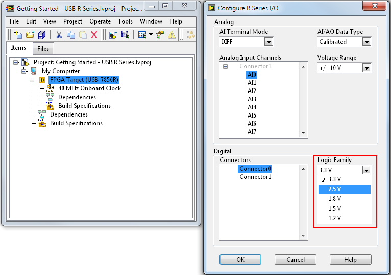
You want to right click on the Target FPGA and click Configuration of change...
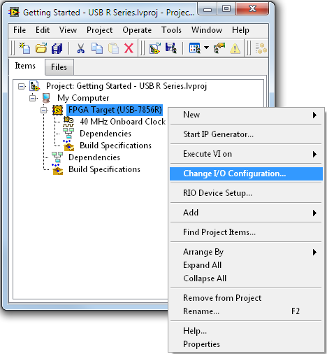
Then, you can set the logic levels.
More details in the help and in this tutorial:
Configuration dialog of e/s series R - OR-RIO 14.0 software help
http://zone.NI.com/reference/en-XX/help/373197D-01/target2devicehelp/configio_dialog/
OR R series for USB getting started part 2: Advanced
http://www.NI.com/Tutorial/14837/en/
Tags: NI Software
Similar Questions
-
Output different from essentially the same IDML for output types different
I'm testing improved site Web locally that uses ID CS6, I have running via the command prompt. The page first displays a preview of the file .jpg, you design that works properly. When the user is finished editing the document they record in a PDF, but that PDF is never the jpg, that a group of fields are still missing.
I extracted all the content files used to generate the two files and combed IDML through them, and they are essentially identical. The only difference between them is any reference the path of the IDML file and I'm passing to ID to generate the file type.
Here's the JPG

And the PDF

I can provide excerpts from any found in the IDML file if it helps.
Any help is appreciated!
So I found the solution myself.
When I compared the XML files found in the IDML I was not concerned with the XML syntax, as well as all XML files valid. All what InDesign Server uses to parse XML apparently is not conform to the XML standards because it is not analyzed this correctly:
It requires the following syntax instead or it does not appear to properly analyze causing content generation sloppy like that seen in my OP.
Hope this helps someone else down the line.
-
NI USB-7855R AO maximum control current
Hello!
I'm looking for the maximum intensity on the USB-7855R NI AO.
In the http://www.ni.com/pdf/manuals/375943a.pdf user manual
There is "Minimum current ± 2.5 drive my ' on page 6, is it error (maximum)?
This value for 1 independent channel or maximum load on all the outputs?
Thank you very much!
Hajar,
An update, you can consider a maximum since the unit can be used with down currents and the value represents the current driver per channel and is not an aggregate.
-
It is current on the analog module USB NI 9263 output voltage limit (+/-10 v)?
It is current on the analog module USB NI 9263 output voltage limit (+/-10 v)? I try to run a current controlled resistance, but cannot get the required current. The servovalved has a parallel internal resistance of 80 ohms and requires 20 my full operation. Ohm's law: (.02 A) * ((80*80) /(80+80) ohms = 4.5 v) Yet, the required voltage, do not move the servo. Outside the material error (continue this by other means), what could be the problem?
Have you checked the Manual?
Page 12 1 says my.
For servo, you really need some kind of amplifier. See if the manufacturer provides the electronic driver for it.
-
are there different scales of two waveforms of the oscilloscope
Hello
I am writing two waveform on the oscilloscope. But one of the wave are very small scale.
Y at - it any wave of scale are two on the graphical indicator of waveform so that the small signal can have higer resolustion?
Thank you!
Hi tian.
Seek the help of LabVIEW for 'scale double y"...
-
Original title: problem of USB ports:
I have a computer dell laptop inspiron d1420 provided with Windows vista and I have upgraded to Windows 7 ultimate, I noticed that when I plug in a USB mass storage, when I try to remove it, I don't get the safe delete the message and lately when I try to remove it, I keep getting the message He's busy and I can't remove it. I tried the same USB on another PC and I have no problem at all. I connected a printer, USB cable and wondows llok have not the driver or didn't install the printer, he left as a device not specified with the name of the printer, but I can't print. I tried with another PC that is also running Windows 7 ultimate and I have no problem, windows has installed the driver, because I used the same printer and the same cable. What is the problem with my USB 4 ports and how to fix?
Hello
When you get this message while trying to remove a USB, it's basically a lock for this USB device by some process running on the computer. If we know which process is this locking mechanism, we could also find which Service is associated with this problem in the computer.
To check this, you can use a program called Process Explorer. You can download this program from the following link. Once downloaded, extract the contents of the zip downloaded to a folder on your desktop. Inside this folder, you will see a file by the name of procexp , which is the executable for Process Explorer. The download link is:
http://TechNet.Microsoft.com/en-us/Sysinternals/bb896653
First, plug the USB to one of the USB ports. Then, once you have the executable to Process Explorer, right-click on it and then click run as administrator. Please allow all guests UAC can occur. Once the Process Explorer is running, please follow these steps to search for processes using the USB at the moment:
1. click on Searchand then click on manage to find them or DLL on the options menu at the top.
2. then in the pop - up which will turn up next, type the drive letter for the USB drive connected to the computer (for example G: or H:) right now and click on Search.
3. he should then display all instances of the process that is using this USB at the moment with the corresponding process ID (PID).
Now, once you have the names of processes using the USB at this time, you can terminate them by clicking on them and then clicking on Manage close. Once this is done, you should be able to eject the USB safely.
I would like to ask the names of processes lock the drive in your computer. This should give us an idea of what we might have to take the next.
In addition, for the other issue that you mentioned, in which the computer does not automatically and correctly detects the printer when it is connected to the computer, I suggest you to check whether or not your computer Plug-and-Play service is set to automatic. Here's how you can do this:
1. press the Windows and the R on your keyboard to get to the top of the run box.
2. type Services.msc in the run box and press enter on the keyboard. Allow all UAC prompts that may coming up next.
3. once it opens the window of the Services for you, scroll down to the Plug-and-Play service and double-click it.
4. in the properties box that will come next, the Startup type should be set to Auto and the Status of the Service must be started. If this isn't the case, please put these values.
5. click on apply then OK, close all windows in the computer and restart the computer once.
Once these steps was performed, please check if the problem remains the same. We know the results.
I hope that these steps raises you in the right direction in order to solve this problem. Don't answer if you still need assistance, we will be happy to be of assistance.
-
Script for random switch between different waveforms
Hello.
How correctly to write the script to switch between different waveforms when generating?
For example:
We use the niFgen allocate named Waveform VI to allocate three waveforms. When you run the generator, the first forms of wave of work. Then the generator is activated and used in the following waveforms only second and third.Or, we have configured 10 waveformsand by train to spend no fixed cyclically between everyone, but only between 2 and 5 waveforms.
If it is possible to achieve?
Max O.
Developer of software and engineering,
TeSLa.
Hi Max,.
Each stage needs, too. End ifs should take place at the end. For example:
If scriptTrigger0

    generate a myWfm0

on the other

    If scriptTrigger1

        generate a myWfm1

    on the other

        If scriptTrigger2

            generate a myWfm2

        on the other

            / etc...

        end if

    end if

end if
Of course, it must all be encapsulated in a repeated structure to continue checking for triggers.
Kind regards
-
NI USB-6501 digital output problem
Hello
I use DASYLab v.11 and I'm working on an interface with the NI USB-6501 where I'm putting a digital high on four ports.
With the module "NOR-DAQmx - digital input", I managed to read the digital inputs of the ' NI USB-6501 ".»
It's only the "NOR-DAQmx - digital output" I can't go to work.
Using 'NI MAX' of NOR I have easily can emmit my four LEDs in the way of my High/Low ports.
But not with DASYLab. When you use DASYLab tension on the ports remains unchanged.
Now, I have a switch module, generating 5/0, directly connected to the digital output module, which is assigned to my four output ports for my task.
I also tried with a module of relay between the two without success. I also tried to use 1.5 above instead of 5 without success.
I use the option 'Bus (0/5 supply) for the module "Digital output".
"NI Max", I configured the ports as "active drive.
Any suggestion of what I might be missing?
Thank you
Martin
Hmm, four ports, or four lines?
A port consists of eight lines. Each line can control an LED (ON / OFF ~ 0/5V).
If you have created a task to dig-out to control a port, 5V to this port sending sets all lines of this port to 'high '.
You need to 255 for each line one too high port (at the bit level: 128 + 64 + 32 + 16 + 8 + 4 + 2 + 1).<- eight="">
Or, you can create a dig out tasks to control four lines of a specific port.
Four lanes of the EEG DAQmx DigOut module.
Each of the channels of the modul will feed a single line of the task/device.
Four switches will then turn the lights, or turn off.
Make sure, that the 'bitposition' is the number of correct line (see picture).
-
OR PCI-6542: Creation of dynamic waveforms using the HSDIO library
Hello!
I have problems to understand how to create waveforms using the HSDIO library to run on a card PCI-6542. I need to create a program that activates a channel for 12.5 microseconds, waiting for a while (i.e. 100 samples) and activates another channel to 12.5 microseconds.
This program must be used in a Multielement ultrasound system.
Here the example of dynamic generation program that transforms the channels 0-2 on 1024 samples.
/************************************************************************
*
* Example program:
* DynamicGeneration.c
*
* Description:
* Generates a simple model on the specified channel.
*
* Pin connection information:
* None.
*
************************************************************************// * Includes * /.
#include "niHSDIO.h"./ * Sets * /.
#define WAVEFORM_SIZE 1024int main (void)
{
ViRsrc deviceID = 'Dev1 ';
ViConstString channelList = "0-2";
ViReal64 sampleClockRate = 50.0e6;
DataWidth ViInt32 = 4;ViUInt32 waveformDataU32 [WAVEFORM_SIZE];
ViConstString waveformName = "myWfm";
ViInt32 timeout = 10000; / * milliseconds * /.ViSession vi = VI_NULL;
Error ViStatus = VI_SUCCESS;
Bruno errDesc [1024];
ViInt32 i;/ * Initialize generation session * /.
checkErr (niHSDIO_InitGenerationSession)
Deviceid, VI_FALSE, VI_FALSE, VI_NULL, &vi));/ * Assign channels for dynamic generation * /.
checkErr (niHSDIO_AssignDynamicChannels (vi, channelList));/ * Set up the clock sample parameters * /.
checkErr (niHSDIO_ConfigureSampleClock)
VI, NIHSDIO_VAL_ON_BOARD_CLOCK_STR, sampleClockRate));/ * Query the data Width attribute * /.
checkErr (niHSDIO_GetAttributeViInt32)
VI, VI_NULL, NIHSDIO_ATTR_DATA_WIDTH, & dataWidth));
/ * Fill the waveform with ramp data * /.
< waveform_size;="">
{
waveformDataU32 [i] = i;
}checkErr (niHSDIO_WriteNamedWaveformU32)
VI, waveformName, WAVEFORM_SIZE, waveformDataU32));/ * Start the generation * /.
checkErr (niHSDIO_Initiate (vi));/ * Wait for all the generation * /.
checkErr (niHSDIO_WaitUntilDone (vi, timeout));Error:
If (error is VI_SUCCESS)
{
/ * Print result * /.
printf ("made without error. \n") ;
}
on the other
{
/ * Get the description of the error and print * /.
niHSDIO_GetError (vi, & error, sizeof (errDesc) /sizeof (petitioner), errDesc);printf ("\nError encountered\n===\n%s\n", errDesc);
}/ * log * /.
niHSDIO_close (vi);/ * prompt to go out (for the popup console windows) * /.
to continue...\n");
GetChar ();error return;
}Issues related to the:
How can I change the values in waveformDataU32 to create market reports (instead of just always on)?
How to select the channel waveformDataU32 is applied to the?
Thank you!
Zachary Geier
The waveformDataU32 table is an array of 32-bit integers. Each bit corresponds to a line on the device. On the first clock cycle, this program outputs:
0000 0000 0000 0000 0000 0000 0000 0000
Then it displays the following, changing at each clock Pulse:
0000 0000 0000 0000 0000 0000 0000 0001,
0000 0000 0000 0000 0000 0000 0000 0010,
...
and so on all the way up to 1023:
0000 0000 0000 0000 00000011 1111 1111
In the example that you include at the bottom, you set the least significant bit (LSB) to zero and one, actually only change one line on the output. To change all the lines, you must instead use 4 294 967 295 or 0xFFFFFFFF:
< waveform_size;="">

     < 200){="" if="" sample="" number="" is="" less="" than="">

          waveformDataU32 [i] = 0;     Disable channels 0-2

     }

     else {}

          waveformDataU32 [i] = 4 294 967 295;     Otherwise turn on all channels to 800 samples

     }

} -
Why my output signal is produced waves triangle when I want the sine waves
in labview I use the daq assistant to create an output voltage signal to create a sine wave. When I connect it to the opscilloscope, it reads the triangle waves. is someone can you please tell me why this is.
9172 is a chassis so I need to know the module you use, too. You should try the example:
%ProgramFiles%\National Instruments\LabVIEW 2012\examples\DAQmx\Analog Output\Voltage - Output.vi continues
It shows you how to create a waveform to generate, you could use this piece and feed in your daq assistant.
-
Acquisition of images with 3 USB cameras causing too many uses of the memory/cpu
Dear experts,
I'm trying to capture images with 3 cameras USB, located in 3 different positions. I have to initialize each cameras using USB list vi camera when switching between cameras. I realize that, by making this method causing too many uses of the memory/cpu and can cause CPU hang up. If I stop the program, the memory/cpu counter are down.
Do you know how to reduce this problem.
Thank you
Hart
-
sound card output audio separate in the left and right channels?
Hi all
I work and change the Sound.vi "generate".
It works very well, however, I want to control what going on the left audio channel vs right.
Down the blockdiagram and the sub vi:s that I actually lost where the tone 'mono' rectuangular Rejoinder to stereoright and the left channel.
Any ideas, inputs are welcome :-)
Just use an instance of the output of his writing have a 1 d waveform data entry (i.e. type Audio output (DBL) writing). Each element of the array corresponds to a channel. You change the type of click with the right button on the service and make a "select Type". Oviously, the generation of waveform in the example will be changed as well.
-
NI USB-6009 digital outputs are active when connected to a PC - I'm not that
I have a small problem:
All outputs digital NI USB-6009 module become active when the module is connected to a PC when no VI is running.
As soon as I start my VI, which controls the module, all the outputs are disabled (now inactive).
How can I achieve this, outputs are inactive if the module is connected to a PC with no program running?
johanneshoer wrote:
I have a small problem:
All outputs digital NI USB-6009 module become active when the module is connected to a PC when no VI is running.
As soon as I start my VI, which controls the module, all the outputs are disabled (now inactive).
How can I achieve this, outputs are inactive if the module is connected to a PC with no program running?
The USB-6008/6009 case has a pull-up internal (4.7 kOhm) resistance. This causes the outputs digital on the device to have a startup logic high State. t is not recommended to use some sort of resistance of menu drop-down. However, what you can do is add octal buffer like the 74HC541 stamp and a digital output to control the sorting of the 74hc541 state mode. Connect the OAS and CEO input signal. A Summit on the pins of the latter will be sorting the output of the buffer State. Therefore, no output signal will be present until you pull the stems of low control. The USB-6008/6009 case have a 5 volt output (200mA max), you can use the buffer.
-
How two graphic signals, taken at different times on the same chart?
Hello
I am trying to graph 2 files different tdm on a chart. The files are the same
Time Sensor 1 Sensor 2 Difference Sensor 3 03/07/2013 08:26:30.214 AM -0.001 0 0.001 3.2109957 03/07/2013 08:26:31.489 AM -0.001 -0.226 0.225 3.251679525 03/07/2013 08:26:32.249 AM -0.149 -0.198 0.049 3.1567506 03/07/2013 08:26:33.192 AM -0.135 -0.248 0.113 3.315462225 03/07/2013 08:26:34.336 AM -0.135 0.17 0.305 3.2682213 I need graphic of the two signals (time vs 3 sensor data from two different files). The registration of signal rate changes by file and within each file, so I need to keep the time interval between each reading, but a necessity, the two waveforms to chart on each other, no matter what day/time, each file was saved to. Please see attachment for an example.
I can read data from the file and graph several waveforms (generic of generated sine waves) on the same graph, is the part that I'm stuck how to get x/time-axis to work properly.
Thank you
Two options:
(i) use relative time instead of absolute time. If dt is not constant, you cannot use waveforms. Use an XY graph and subtract the time stamp first of each timestamp in the data/file set. Either your departure time will be zero (or 1904 if you want).
(II) draw the two sets of data in a XY Chart, using two x scales. With the right button of the x-scale and select "Duplicate scale" (or something close to it), then go to 'Settings'-> 'Ladders' and change the new scale. Now go to the tab 'Traces' (always in 'settings') and configure your two plots using separate x-scales.
-
Pull-up external USB-6009. digital output (open collector) allows onboard external + 2.5 V output?
Pull-up external USB-6009. digital output (open collector) allows onboard external + 2.5 V output?
Hello
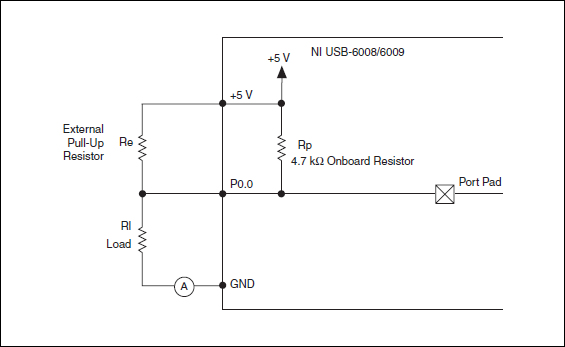
I want to config output digital USB-6009 to + 2.5 V above and 0 V digital output low. I know I can config USB-6009 digital output open collector with resistance to pull-up external, that can be applied with + 2.5 V power source.
My question is: can I use USB-6009 Board + 2.5 V output as the current source of resistance to pull-up? What resistance is a good number for the resistance to pull-up, if I can use this configuration?
Thank you much for the help.
Cathy
Hi Cathy,.
The digital USB 6008 front-end server looks like this:
So, there is actually an internal pullup to 5V 4.7 kOhm resistance when the device is configured to open collector.
If you want to display 0 to 2.5 V, I would look in a resistance of polarization of 4.7 kOhm between c and ground (according to the rest of your tour).
Best regards


Maybe you are looking for
-
http: this Web site provides information on the property. solve the
I am the owner of the site and have been for the past eight years. I hope that my company is considered responsible and honest. I would like to stop Firefox giving a warning that I can fix it. So, how to provide "information of property? What firefox
-
Hello I bought the new Imac 2015 retina (4 GB RAM) last month. I was surfing the internet when suddenly a problem as it appeared: https://www.Flickr.com/GP/_ego_/8R0TPx I don't know why, but now my iMac is much more slow and unstable. A way to fix it
-
iMac 2009, 21.5 inch, OSX Yosemite 10.10.5 I replace my computer soon, after many years of good, and one thing that always gives me peace of mind is my Time Machine backups to an external drive (Seagate Free Agent 1 TB). My computer had about 800 GB
-
I am using windows xp sp3 and often get a blue screen usb_bug code. Is there a permanent solution. Rgds.
-
OfficeJet Pro 8615: Fax a lot of page at a time
I used my all-in-one for faxing several times beautifully, but when I need to send a response to an offer of our agency of 33 pages, I guess it was too much to do at once, then divided into two separate Fax. The first batch was 16 pages, but stuck on