ni6602 100 kHz clock
Hello
I have another question. I work with NI6602 Countercard. I've implemented a LabVIEW code in 2013 to use this card.
It already works fine without problems. Yesterday, I learned how to connect the internal clock to 20 and 80 MHz to one of the strings. This also works very well.
In the description /Plug it seems to also be a 100 kHz clock, but I can't find this clock in the drop-down menu that allows you to select the clock (DAQmx Propertynode: CI.) CountEdges.Term).
No matter who worked with NI6602 and also connected internal clocks?
Do you know if this 100 kHz exist or is it just on paper?
If you're wondering why we do this:
This NI6602 is a part of the great DAQ system and we want to use this clock for synchronization. To explain everything in detail, it would take a while, but I also think to answer the question, is it not really necessary.
greetings and thanks
Christian
Hi Christian,
If you change the settings for the constant/control of the synchronization source (check all boxes) the time base of 100 kHz takes place.
Philipp K.
AE | OR Germany
Tags: NI Software
Similar Questions
-
Hi all
I use the NI PCI 6723 Analog Output card with SCB-68 connector housing. Specifications of the PCI-6723 tells this unique channel of sampling frequency (refresh rate) maximum is 800 Ksamp/s. I tried t0 generate sine wave 100 KHz using single channel only in continuous mode with + / 10V range defined using Labview Signal Express application, however, output of the DAC was very distorted (a kind of triangle instead of waveform sinusoidal waveform) and amplitude of output even reduced to about 2 or 3 V and becomes not symmetrical (i.e. not centered around 0V).
Then I found that the generation of signals up to 20 kHz, output DAC was very well without any distortion amplitude or form, however as I go beyond 20 kHz (with constant update of rate of 800Ksamp/s) to 100 KHz, CAD production has started to become more, and most corrupt.
Kindly tell me if NI PCI-6723 is sufficient to 100 kHz signal output if I use only single channel?
And if so, what can be the reson for this distortion?
Thank you
Best regards
Asim
It seems that you exceed the maximum scanning speed for the card, which is probably why you see distortion on your waveform. Scanning speed is defined as the maximum rate of change of output voltage per unit of time. The map (from the manual, link below) has a maximum speed of scanning of .7V / us, you are exceeding that by a significant margin.
NEITHER 6722/6723 specifications
http://www.NI.com/PDF/manuals/370822c.PDF
To resolve this problem, you can either reduce the frequency of your signals output, or you can decrease the amplitude of the wave. the two changes will reduce the scanning speed. You will need to reduce one or the other enough will be the maximum scan rate specified map.
So, long story short, the card is not able to produce a sine wave of full scale at 100 kHz due to the limitation of the maximum scanning speed. You should be able to output a signal 100 kHz if you reduce the amplitude of your waveform.
Kind regards
-
672PCI 6723 error when you try to generate a signal with the sample of 20 kHz clock
I have a piece of code that worked successfully on the PCI-6224 map, but when I tried to implement the same code on the card PCI-6723 I ran into problems.
Here is the code I use:
ManchConversion6723();//produces SendIt array of series of 1s/0s

// DAQmx Configure Clock
DAQmxErrChk (DAQmxCreateTask("",&taskHandleFRQ));
DAQmxErrChk (DAQmxCreateCOPulseChanFreq(taskHandleFRQ,"Dev3/ctr0","",DAQmx_Val_Hz,DAQmx_Val_Low,0,20000,0.5));
DAQmxErrChk (DAQmxCfgImplicitTiming(taskHandleFRQ,DAQmx_Val_ContSamps,72));

// DAQmx Configure Digital Output
DAQmxErrChk (DAQmxCreateTask("",&taskHandle));MessageBox("D");//vj
DAQmxErrChk (DAQmxCreateDOChan(taskHandle,"Dev3/port0/line0","",DAQmx_Val_ChanPerLine));MessageBox("E");//vj
DAQmxErrChk (DAQmxCfgSampClkTiming(taskHandle,"/Dev3/Ctr0InternalOutput",20000,DAQmx_Val_Rising,DAQmx_Val_ContSamps,72));

// DAQmx Write Code
DAQmxErrChk (DAQmxWriteDigitalLines(taskHandle,72,0,10.0,DAQmx_Val_GroupByChannel,SendIt6723,NULL,NULL));

// DAQmx Start Code
DAQmxErrChk (DAQmxStartTask(taskHandleFRQ));
DAQmxErrChk (DAQmxStartTask(taskHandle));
When I get on the DAQmxCfgSampClkTiming line, I get an error stating:
DAQmx error: measurements: request the value is not supported for this property value.
Property
 AQmx_SampTimingType
You asked: DAQmx_Val_SampClk
You can select: DAQmx_Val_OnDemand
Task name: _unnamedTask<0>
State code:-200077
I think that the problem comes from the variable of the source of the function. I'm just tring to send the data to the frequency of 20 kHz.
Any help would be greatly appreciated. Thanks in advance!
Too bad. The impression that the PCI-6723 does not contain correlated DIO channels. In other words, examples of clock cannot be linked to the DIO channels allowing the generation of digital waveforms. According to the AO Series user manual, this applies to the NI 6731/6733 only. The mistake was trying to tell me that only a single issue or receive channel has been authorized.
For this reason, I'll stick right with my card PCI-6224.
Sorry for the confusion.
-
Hi people,
I have a challenge I'd like to discuss with you and hope to have some ideas and maybe a solution.
I have a systems acquisition (DAQ) Multifunction National Instruments NOR-PCIe-6353 means X-Series!
I would like to generate and measure signals pulse width modulation .
DRIVER:
OUTPUT:
FREQ: 0, 1 Hz - 1 MHz
Duty: 1-99%
Change the setting on the fly
(This works very well and is implemented)
ENTRY:
FREQ: 0.1 Hz - 40 kHz
Duty: 1-99%
Method of measurement: period of semi / ContinuousSamples / AsyncCallback
Here, I have problems I am running only on an Intel Core 2 Duo CPU E8500 @ 3, 16GHz.
And I want to run 2 PWM_IN and PWM_OUT 2
Low frequency work fine!
0.1 Hz - 20 kHz
It is a loopback with
myCounterReader_1.BeginMemoryOptimizedReadMultiSampleDouble (2, myCallback_1, myPWM_IN_1, myPWM_IN_1_Data);
Data = myCounterReader_1.EndMemoryOptimizedReadMultiSampleDouble (ar, on myPWM_IN_1_Data_actualNumberOfSamplesRead);
A higher frequency do not work very well!
20-40 kHz
I get exception Code of State-200279:
Attempted to read samples that are no longer available. The requested sample was already available, but has since been replaced.
Increase in the size of buffer, most frequently the reading of data or by specifying a fixed number of samples to read instead of reading all available samples would correct the problem.
Property: Value of NationalInstruments.DAQmx.DaqStream.ReadRelativeToRequested:
NationalInstruments.DAQmx.ReadRelativeTo.CurrentReadPosition
Property: NationalInstruments.DAQmx.DaqStream.ReadOffsetRequested value: 0
Task name: NI1_PWM_IN_ctr0
State code:-200279
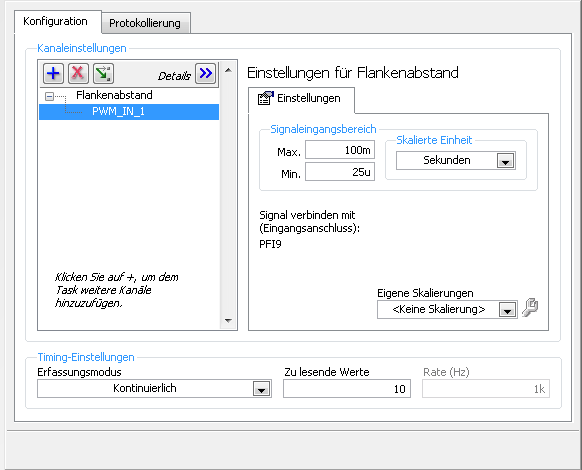
40 kHz, period is 25us = 12, 5 HighTime and 12, 5 LowTime 50% DutyCycle
This means that each 25us I get a reading of 2 samples the HighTime and the LowTime
I charge my task of Max, so here's the Setup (sorry its german):
1 can someboby you explain to me what the MemoryOptimized?
2 Zu lesende values means that the size of the buffer 10 is not much but increases the size of the buffer to say 10,000 needing help on
a longer time!
3. playback of data more frequently is not possible because the data are under tension, because it is
4 specify a fixed number of samples I der number is HighTime 2 and LowTime
5. I have does not start and stop the task! Is it better to start and stop the task each time while I still may have a new buffer?
I hope someone has an idea for!
By
Steven
Reading with 50 software we period - bad idea, you will jump impulses. Try to use DAQmx Read Overwrite property, set it to "crush the unread samples" - it will overwrite the impulses without error.
-
Get samples of the clock machine (NEITHER with NOR cDAQ-9172-9422)
Hey guys
I'm trying to produce data for the position of a 1000 Hz all about stamping press with an absolute encoder which is connected to the NOR-DAQ.
Two not that I am trying to program, but can not understand:
(1) use a hardware clock to trigger the acquisition of the data at the selected speed
(2) synchronize the three data acquisition modules I have to ensure that all data are received at the same time
the material I have does not seem to have any counters. A few examples that I read would not go because of this.
Any thoughts? If there is some examples/tutorials about this problem that I have missed please let me know.
Thank you
Hey, Rohan,.
Thanks a lot for your help. I was talking to a National Instruments process engineer yesterday and it me that the problem was the vi calendar clock source option - instead of using AI/SampleClock, I had to use the time base of 100 kHz clock that did not appear in the list until I checked the option "ListAdvanced Terminal" in the name of e/s filtering dialog box. You must right-click the constant/control of the source of the clock and select I/O name filtering to open this dialog box.
Thanks for all your suggestions, I'll try to apply it and check the performance.
Nik
-
Hi all
I have this suite solution VI resulting LabVIEW example for continuous digital data output. The question is about the system clock - if you select a value of low sample rate (say, 1 s/s), the rate seems to be much higher. The light on my BNC2120 is dimmed on the whole; which indicates a rapid change between the Low and High?
How can I change the closed VI actually write a sample per second? I use the PXI-6132 card.
Thanks in advance.
If you use 100 kHz clock, then do a waveform high for 100,000 samples and then low to 100,000 samples. You will then have a table of 200 000 samples to write.
-
With the API c for linux, how can I decimate the clock at a 10 kHz signal?
Hiya. I know that the clock signal is decimated on the chessboard in a few places... is there a function in the linux api c for export a decimated signal? Can I choose any arbitrary decimation, or am I limited to the various bases of time used on the map (a series of M in my case)?
Thank you!
You use DAQmx (8.0 or 8.0.1)? If so, you have a few options:
Counter output: Available frequencies are {80 MHz, 20 MHz, 100 kHz, external} / {2: 2,32-1}
Output frequency: Available frequencies are {10 MHz, 100 kHz} / {01:16}
Export clock of AI or AO task: Available frequencies are {external 20 MHz, 100 kHz,} / {2: 2,32-1}, but going too fast will result in a material synchronizing error on ADC or DAC.
On the M-series: DAQ there are two counters, a single frequency output, HAVE a single timing engine and a single engine timing AO (if your motherboard supports AO). Simply choose any subsystem available to you. If you have need of a constant 10 kHz and then the frequency output is perfectly adequate, it is programmed similar to a meter output (reference Dev1/freqout instead of Dev1/ctr0).
If I remember correctly (I'm on Windows for now), on Linux the C ANSI DAQmx examples should be installed in \usr\local\natinst\nidaqmx\examples. It should be an example of output included continuous meter.
Best regards
-
How to get a regular clock (100 MHz, 10 MHz to 20 MHz) of the NI 4462 PCI?
Is it possible to extract a regular clock, high frequency of the 4462 OR?
I need to synchronize with another card (a PulseBlaster), which requires a 100 MHz clock: every card can be the main source, but they must stay perfectly synchronized.
(Both cards have on-board crystal oscillator modules of 100 MHz; one of the PulseBlaster is nested, would be so easy to connect a source external intead)
I use the PCI version, so the star PXI 10 MHz clock is not available. The 10 MHz or 20 MHz clocks that DAQmx usually exports seem not to be available for routing on this device.
I can't use the Sampleclock, because it is variable (~ 25.6 MHz, changing with sample-freq) and because it is not active when the 4462 is actually measurements.
In addition, this clock must be either 100 MHz, or a whole simple fraction of it (e.g. 10 MHz, so that a PLL can re - generate the 100 MHz).
At the present time, the best option seems to be to solder on the 4462 output pin quartz oscillator - but it's a really ugly way do... has anyone had an experience to make relevant changes?
Is there a better place to connect to? I would prefer to use the RTSI bus connector, but despite tempting advice in the documentation, it seems not possible to get out of the 10/20 MHz master time base: there is
an axis called RTSI7/RTSI_OSC, but it is a permanent decline.
Thanks for your help.
Nick Dear,
Thanks a lot for your help. As you say, this confirms what I already knew.
But we really need keep everything in harmony. So, here is what I did, which should hopefully help someone else in the same position.
The circuit is very simple, using a FIN1001 LVDS line driver. It is a SOT-23 package. Connections are the following:
* Din connects to the output of oscillator 100 MHz (TC0-2104, pin 4).
* Gnd connects to the Earth (C210, lower)
* + 3v3 connects to the more accessible place, that TCO-2104, PIN 6. [The 3V3 regulator is on the back of the map]
* FIN1001 food is decoupled with a 0.1uF adjacent capacitor.
* Dout + and Dout-are connected to a short (30cm long) of the unshielded, twisted pair made of wire 0.7 mm PTFE. (Z ~ 110 ohms)
Photograph is attached. The SOT-23 package is physically secure, with a tiny drop of cyano, C210 and mounted on his back.
The receiver uses a FIN1002 receiver, finished with 100 ohm twisted pair and uses a 74VHC04 to convert 3.3V 5V TTL.
It is mounted on a 14 pin DIL socket, to plug directly into the socket on the other card PCI which normally has its own oscillator module.
Result: everything works, and I have a 100 MHz clock available to drive the other timing card.
-
Synchronization of analog and digital output with the external sample clock
Hello
First of all sorry for my English, I will try to explain what I want to do.
I want my PCIe-6321 to send two custom signals (modification sawtooths) on a mirror controller. I would also like to generate output with my card at the beginning of each tooth of saw. Everything must be synchronized with an external k-clock signal of 100 kHz. The idea is that whenever the PCI receives a trigger to external clock, it sends two analog output voltages and when he received 1024 clock ticks it will also send a pic of triggering TTL. What I do is first prepare the map and after that in a loop sending and modifing the output values of the two signals and at the same time send a digital signal Boolean in each arch, so when's done it 1024 iterations of the loop I send an event to the digital port. Attached you can see.
The problem is that I don't know how to synchronize both. Can I use the sample clock just to the analog output? I can use sample for the two outputs clock, or do I need to use the output of the meter? If don't know how to use it here.
If I do nothing else bad/wrong, I would be grateful for feedback.
Thanks in advance,
PabloI don't know how but I find the solution. I'm generating more than a positive value (as I was triggered maybe very fast the oscilloscope has been absent there). If I put the sample clock of digital output to use the sampling/ao/Dev1 clock that it doesn't, but if I put to use the same source as the OD (terminal where my external clock is connected), but the trigger to start the DO to be Dev1/ao/StartTrigger this works. I don't really know why, but it does.
Thank you for your patience and your help. I put here the final code.
-
cDAQ HAVE task using external clock
Hi, I am trying to use a clock signal on a line of PFI in order to generate a clock, but at a lower rate, for a task to HAVE. I run into many issues that I can't explain.
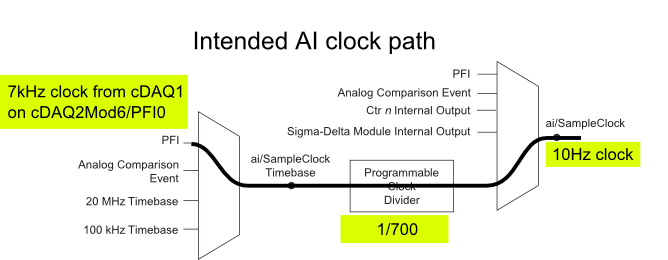
I have a cDAQ-9172 with an entrance module analog (9225) in the Groove 3 and a digital input module (9411 - 2 MHz DI) into the slot 6 (where the PFI lines are accessible). I want to use an external signal on et0/PFI0 to act as the clock for an analog input on the 9225 task. This signal comes from the cDAQ anothr chassis and is too fast for the task to HAVE it, so I intend to use the time base entrance and the divider to clock (as shown on page 31 of the cDAQ-9172 manual). See picture attached for a graphical representation of my problem.
If I have the wiring from the signal "/ cDAQ2Mod6/PFI0" in the DAQmx timing VI, get the error 200414 saying that "required sample clock source is not valid." It is strange because it is listed as "Direct route" in Max (the VI of polymorphic DAQmx Timing is configured as 'Sample clock') Q: why this route is not suitable for the task?
If I use DAQmx Timing property node and change the Source 'Sample clock Timebase' to ' / cDAQ2Mod6/PFI0 ", the task starts without error, but the separation seems to be forced to 256. If I try to change the properties of the separation of the time base, I get error-201100. Try to change the 'sample clock rate"doesn't have any impact on the task and the remains of divider"256 ". Q: why the 'Programmable clock divider"locked to 256 when using the PFI line or can you just not program directly?
I came across another error is the minimum speed on the PFI line. If I have the wiring (for the SamplClock Timebase) lower at 1 MHz, LabVIEW returns error-200077. The error message indicates that the minimum value is 1 MHz. 9172 manual shows the clock 100 kHz is an option for the time base, certainly less than 1 MHz. Q: What are the limits of upper and lower frequency for a clock signal on the line PFI for the ' Timebase AI/SampleClock "?
I looked on the site and in the DAQmx documentation for further explanation, but I have been unable to explain these strange behaviors. What are the barriers to entry of Timebase PFI and the time base "Programmable clock divider" preventing me to reach my goal here? If I can't do it directly, can I use the PFIn signal to feed an internal counter (to act as the clock divider) which could then generate the clock WAS at the rate I want? This method would allow me to perform a division arbitrary clock (unlike the ' 256', which seems to be forced on the PFI as a Timebase SampleClock.)
Finally, something seems odd that I can make an acquisition to 10Sa/s max but when I start a task using an internal timers of the cDAQ9172 and ask a 10Sa/s rate, the task really gives me a rate of 1612.9 sample/s while using the 12.8 MHz clock and a divider 7936 timebase. Q: Why can't the task to 10Sa/s?
I use DAQmx 9.7.0 and LV2012 SP1 (and I tried with 9.7.5 but I got the same results)
Thank you
Olivier
I got additional help Friday in another engineer at NEITHER and the solution to my original problem is actually very simple to get the clock from an external source path:
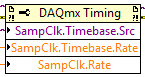
The idea of picking a PFI line for the basis of 'time' and the 'Programmable clock divider"(in fact, DAQmx calculate this number based on"HAVE sample time clock"and"Sample clock HAVE") works by using the node property below:
(SampleClock.Source cannot be resolved until the task is clerks/reserved, but the default option seems to be the time base that works well in this case.)
The question that I described earlier with the 9225 comes the module properties and the fact that it is a "Module of Sigma - Delta". That the module usually generates its own time of 12.8 MHz base clock (page 14 of the document 9225 # 374707) and the clock divisor is much less possible values than the other modules (must be a multiple of 256). It may use a different time basis from a PFI line, but it must be between 1 MHz and 13.15 MHz.
So a main clock between two chassis and tasks running at different rates of sharing should be easy and simple with most of the modules. With AI modules with Sigma-Delta converters add additional limitations and the master clock for the time base frequency must be selected to accommodate these module as well.
Another good news is that the Simulator seems to bear all these details and DAQmx (9.7.0 in my case) generates the same errors when you use a simulated chassis if you use real body. Play well!
-
9401 buffered output digital clock sample source
Hi, I would like to generate a pulse train with a defined number of pulses, according to a defined periodicity. I use a NI9401 module in the Groove 3 CompactDAQ chassis so that I can write the required buffer sample 2047 pulse train. The problem I have is I am unable to choose any clock source slower than the time base of 100 kHz, which means that the buffer can underflow very easily. I would use a 4 kHz clock source, but cannot find how do. If I want to generate a source of the clock of one of the counters, I must have the 9401 in slots 6 or 7 which then do not allow for generation of digital signals in the buffer...
Hi, JPP,.
Access to internal counters, even if modules are connected in the Groove 1-4 of the cDAQ chassis. Note this site 6 & 7 are necessary only if you need external access to counters as task of counter in the buffer, the measures of frequency/period, etc... Since in your application, all you need is to generate a continuous pulse train and access its output internally to clock output your digital correlated, this shouldn't be a problem with your DIO module into the Groove 4. Please take a look at the following link for more information.
With the help of internal counters on one NOR cDAQ-9172 as a sample for other tasks clock
http://digital.NI.com/public.nsf/allkb/EEB574335BA0B4EB862572060055E9DD?OpenDocument
I would also like to refer to an example on our site which shows you how to use your correlated digital i/o clock counter. I hope this helps.
NOR-DAQmx: Digital Correlation of e/s with NI CompactDAQ and LabVIEW
-
Is it possible to use the internal clock for meter tasks in the buffer?
Hello
Hardware: USB term mass 6251
Software: LabView 2011 SP1
I need to measure the angular lever position and speed of a carpet. For that I use two quadrature encoders. To accurately calculate the speed I use buffered from the measures of position using one of the available onboard counters. I understand that for this technique, I provide a sample for the meter clock. I wonder if it is possible to use the internal time base. Note that both of my counters are used so I can't generate a signal to clock with them.
I found two conflicting pages related to my problem:
1) http://digital.ni.com/public.nsf/allkb/EA7FFFEAFC3E1D85862572F700699530
2) http://digital.ni.com/public.nsf/allkb/775290A3121D1FFC862577140074D3B3
The first says that I can use the internal clock of 100 kHz, and the other says that I have an external clock.
Comments/solutions?
Javad
Hi Javad,
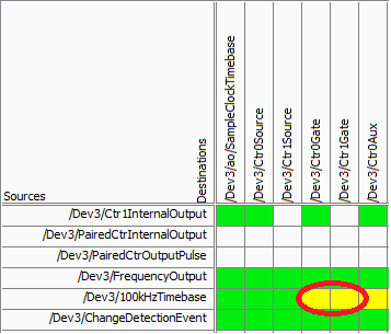
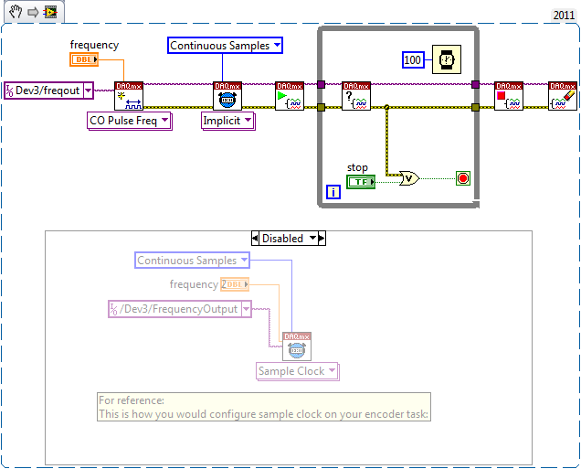
On your specific device, there is not a direct route from the time base of 100 kHz for the meter (according to the routing table of MAX):
Yellow cell indicates that a route is possible but there is not direct (the "gate" terminal is used as sample clock for counters of the M series). Mouse on the cell reveals yellow that make this route really requires the use of a counter (so it is not suitable for your application).
On the line above "100kHzTimebase" you will notice it is called 'FrequencyOutput', which does not have a direct route to the door. This would be the way to go if you want to route 100 kHz (or some other frequency) as your sample counter clock - you can set it up the same way to a standard meter output task:
The output frequency doesn't have that many features like a meter output, but it is able to generate a continuous stable frequency. There are only 32 different frequencies that can be generated using Freq Out on the 6251:
{10 MHz, 100 kHz} / {01:16}
Do not forget that the resolution of your measure of frequency by using this method will be equal to how many times you update the measure (hopefully, that makes sense). In other words, if at the end of all the 1 second, you take the total number of charges since the last second, you would have a 1 per second equal resolution change in the number. If you take the difference twice per second, you would end up with half the resolution. You will be sampling the account register fairly quickly, but you will need only to do the calculation of the frequency after that all N samples in order to obtain a significant number.
Another method that will certainly give a higher resolution in less time at typical speeds of coders is to set up a measurement of the frequency (the counter will count the internal 80 MHz base time period your external signal and the pilot calculates the frequency based on the result). This method uses only a single entry - so you can just feed the 'A' your encoder quadrature signal (the method will not work if you are interested in absolute position or direction). Without using signals A and B together, you will be susceptible to noise (which is common to have a quadrature encoder) that you want to delete (perhaps by setting up a digital filter). Finally, you want to set a reasonable timeout on your reader calls (which will be blocked until a period of your external signal occurs), and the error-200284 handle simply report "0Hz" to make sure that your program is still sensitive even without an external signal present.
Best regards
-
Problems of acquisition & visualization: fails at 100 Hz, OK more low or more freqs
Hi all
I have some data acquisition & visualitzating problems.
The acquired data is a voltage (0 - 10V) from RDP LVDT & conditioner. My pourpose is simple: I want to gain everything by visualizing and recording to disk. I use a card BNC-2101 & 6062E. I also use LabView 8.5 on Windows XP s.p.3. I tried three ways: my own .vi and examples of LabView with internal clock and the external clock. They all consist of two steps: aquire, visualize data on a graph. and my own .vi also saves the data in a .lvm.
On the first try, I was able to acquire data with sample on request mode. But I want to get to a known frequency, so I put 1-sample (controlled HW). I set the frequency and the number of samples as well as the number of samples is of approximately 1/5 of the frequency, for a rate of graphics path 5 times / sec., BUT I found the following problems:
(1) for the acquisition in the low frequencies, say 50 Hz, there is a large gap between read data a shown in the data graphic: from 2 to 8 seconds.
(2) for the acquisition to high and very high frequencies, say 20 kHz to 100 kHz, the graphic works OK. But in this way, the file I'm writing is too much. I don't understand why when I put the computer work harder, with more data, it appears without delay.
(3) for the acquisition to 100 Hz, it does not work. An error (just know don't remember the #, is one who says this time-out has been reached whithout having given to read aviable). 99.9 Hz works, but not at 100 Hz or 200 Hz. I really don't understand this point.
Can someone help me please?
Thank you for your attention,
usuario
Just writing to tell you that we have tried with another computer and had no problems with the hardware and the same .vi.
And have had no problem for the las 2 months.
Thank you all for your dedication.
-
Reading and samples the sampling frequency using a fast external clock
Hello
I use an NI USB-6212 box to launch a search engine for combustion. I have a pressure sensor in the head and a wheel on the crankshaft. I use the beats A Quad channel of the rotary encoder as a sample external to the pressure with the sample clock. The idea is that I want almost the same number of points in each trace of pressure so that it is easy to average together. I seem to be able to do this at low speed, but I'm having issues at high speed.
Can someone tell me what I should have my sampling rate and samples to read together and how it effects my sampling when using an external clock? Samples per channel will affect the size of buffer and that matters? When I was high (10-100 kHz and about 1/10 * rate for samples to read) it barely read but as I put the lowest and lowest he read faster. Play with the settings a bit seem to affect how well it samples at different speeds. The engine is running at 3600 rpm and my encoder puts out 2500 pulses per turn on one channel, I'm looking at a frequency of 150 kHz effective sampling. However I didn't sample program with the engine operating at full throttle. I hung on the output of the encoder up to a scope and reads very well.
Are there opportunities the filter counter that I see in the manual of 621 x is enabled inadvertently?
Thank you
Xander
Xander18,
I suggest you move your screws initialization outside the while loop, as well as your narrow DAQmx VI. On my side, it looks like a new task is performed for each loop, which takes time. That a try and let me know how it goes.
-
Hard, I try to find a solution how to use external ABZ, quadrature encoder pulse to retrigger and clock repeatedly the same AO signals (and). A and B legumes should clock AO and Z-pulse wave should restart the wave early. Is this possible with card 6221? Can provide you the code example?
I use LV8.0
Thank you
Kevin,
Thank you for picking up the thread.
I understand your example and I already had working direct synchronization of the AO and MAKE the waveforms using external impulses. The problem is that my application cannot invoke the correct number of A pulse will run same waveform for months. I have to use Z-pulse to maintain synchronization in the long term. That's why the task should be redeclenchables.
I have made some progress since yesterday on the use of the example attached 'retriggerable_ao - NOR .vi' and the decoder external t.i. IC, which has transformed two 1024 A, B encoder in dish 4096 pulses/turn. My CO task then divides this frequency to 1024 (4 points per period). This regime of AO - redeclenchables DO so usually seems to work.
The problem now is that this chip must have a clock (~ 100 kHz or more) to work, and I don't want to build generator external too.
Y at - there no way to get all the signals of high frequency signals (100 kHz, 20 MHz or 20 MHz base time) USB-6221 Board any PFI available pine asuming that all of my commitments in Task-resource in this example are needed?
I tried a lot of things yesterday, but all the clock signals are either committed or roads are anavailable. I don't understand why I can't tap into it?
Any thoughts?
Mikhail
Maybe you are looking for
-
used firefox update & my favorites have been removed
I used the Refresh feature of ff. now, I've lost ALL my saved favorites. searched on how to get back them, but nothing helped.
-
iOS 9.2 battery drain (iPhone 6)
Then I have updated ios 9.2 tonight on my iPhone 6 (from 8.4.2). I noticed a significant drop in the battery life down 10% in 30 minutes with very little use. He was quite handsome before upgrade. The irony is that I have improved only because peo
-
Microsoft Security Essentials replaces Windows Defender and what is the difference?
Microsoft Security Essentials has a download of much larger definitions (45 MB) Windows Defender (about 13 MB). That means more MSE WD do? The current definitions of MSE download contains the same version of engine 1.1.5502.0 as the current update of
-
I have Window XP Professional version 2002, Service Pack 3 on my computer. Whenever I restart my computer, I get an error message "DriverCure" She says it is a "erreur error installation, please reinstall the application. Problem is that I don't kn
-
One barra of tarefas, e o Menu Iniciar a barra ao lado reţea ficaram brancos, com com os itens a mostra, original I can not voltar a'm e a cor azul, than FACO?