NIDAQmxBase uses differential signals?
I recently updated the NIDAQmx Base to the plus version and. But now I'm a horrible corruption of my signals. I checked with a scope and the signals are correct, but it sounds horrible crosstalk between channels. The only thing I can think is that the Council does not truly differential switching beyond the first 8 channels.
I use a card of 64 channels so there are 32 differential channels, I'm only using 16 channels beginning. I use ' Dev1 / ai0:7, Dev1 / ai16:23 "for the specification of my channel. The equipment works as the default "Datalogger" shows the correct data. But I'm guessing that the data recorder was built with an earlier version of the basis of NIDAQmx. This seems to happen when you use more than the first 8 channels. This VI allows to work with the previous version of NIDAQmx base.
Is this a known issue?
Here's the code to initialize the jury NOR-6033

Mac OS X 10.4.11 PPC / LV 8.5.1 / NIDAQmx Base 3.2.0 / VISA 4.4.0
Hi Scott-
I agree that relocation is the most appropriate next step. I tried here with a very similar setup and I could get the correct number of samples during my reading, and accurate data looked. Please let us know your results once the reinstallation completed. Thank you-
Ed
Tags: NI Hardware
Similar Questions
-
myRIO - measure unique output completed using differential input
Hi all
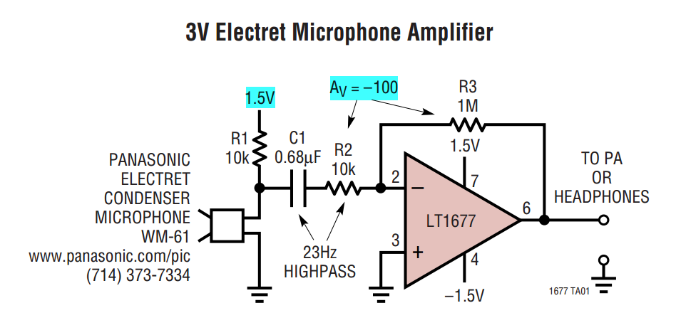
I had used myRIO 1900 to measure the power of the microphone, which varies from 0 to 5V (biased to 2, 5V).
I used one of the analog input ports completed only connector MXP or B to read the value.
A few reasons, I changed the microphone with amplifier and when measured using oscilloscope and other hardware DAQ, supply range of + 5V and - 5V.
As the MXP is unable to read the voltage-ve, I realized that I need to change the connection to the MSP connector C.
It is mentioned in the dataheet of myRIO we can measure up to differential Channels analog input +/-10 V.
Although there are some reference materials available, I do not understand completely how to read the single ended output using differential input.
Should I use no matter what op-amp or comes directly from their phone?
Can someone kindly explain to me the differences and some references on how to connect!
Although I tried to read through this white paper, I felt completely lost

http://www.NI.com/white-paper/3344/en/
Exit ended unique direct and/or the amplifier has 2 pins: GND and Vout
Entered different a 3-pin: A +, A - and ALWAYS
I had attached the screenshot of the form OP amp for your reference
I think that you just connect your Vout to the + ve differential termination, MASS to Terminal - ve. (Briefly) An asymmetric measure is between the channel of GOT it and STILL while a differential measurement is between the + ve and ve - terminal. One measurement unit completed is referenced to GND is where you are measuring the tension of.
-
How to control the mouse cursor using EEG signals
Hello world
I am doing a project of cursor control using EEG signals. The idea is to find a way to all signals in a specific period of time in order to find the signal Ridge. Then, the highlight will be a parameter to control the position of a cursor.
Can someone tell me the function that allows you to control the mouse cursor?
I also found an old topic asking about it (http://forums.ni.com/t5/LabVIEW/Moving-Mouse-using-Labview/td-p/1285842) and I run an example of this link ( smercurio_fc) program. My cursor is stuck in the upper left corner of the screen, I can't control it again. Can you tell me how to run this program and to use the windows API?
Thank you in advance.
Sorry, but I can't do it for you.
As I advised, you should take the free online tutorials. You clearly lacks the basic concepts of LabVIEW, as data flow.
Things more: in your real applicaton does not use DAQ Assistant, screw Express are generally not optimal for data acquisition. It is safer and better use good DAQmx live. What is the equipment you use? Sampling rate, etc.?
Why do you need to read data files? For testing? I thought that you will acquire data active, right? In your VI generate you some signals and write in a data file. Is this also for testing?
There are several constructs in your VI which simply don't make sense.
So again, I really suggest to go through online Core1-2 teaching material, which is accessible if you are a student, or if you have shared services provider license... It will really help.
-
Can I have the user enter a variable that will be used to Signal Express?
We seek to use the Signal Express to collect data of analog sensors and load cells. We would like the user to be able to enter a variable that the program Express of Signal can act on. Is it possible within Signal Express?
Hello
When you select 'Change destination', it will fill with all stage settings that are supported for the given control used. Not all the steps or step settings are able to be adjusted when the operator mode. That is why you were only able to bind controls to step DAQmx Acquire and filter (they are only available to bind in your configuration steps settings). The forumla node is not able to reference an entry of order of the operator interface. You must manually configure the formula tab of configuration step for that particular step.
I would recommend if you want that more customized the user interface and approach programming using an application development environment. Signal Express is ideal for acquisition of signals and perform analysis and basic treatment, but if you want more functionality LabVIEW would be a better option.
-
Im trying to fill the network so my ps2 connections can use the signal wireless to my laptop running vista Basic. When I click to bridge, I get a message saying that I need at least 2 internet connections. is this in any way about this?
Hi Jer9009,
Welcome to the Microsoft answers site.
· Could you give the exact error code or error number you get?
To connect multiple computers, install a network adapter in each and run a network CAT5 cabling to connect each one to a hub (and thus the other.) The computer that will serve as a transition will have a standard network card for wired and a wireless network adapter that will connect to the wireless (WAP) access point or gateway on the second network.
A network bridge is software or hardware that connects two networks or more so that they can communicate. You can create only a single bridge network on a computer, but a bridge can handle any number of network connections.
For more information, see the link: create a network bridge:http://windows.microsoft.com/en-US/windows-vista/Create-a-network-bridge
Add a connection to a network bridge: http://windows.microsoft.com/en-us/windows-vista/Add-a-connection-to-a-network-bridge
Swathi B - Microsoft technical support.
Visit our Microsoft answers feedback Forum and let us know what you think. -
Can I use five differential signals analog usb 6008?
Hello!
I have the USB-6008 housing with one and two potentiometers temperature sensor (and one meter and digital input is also beign used).
I've only got analog +-left slot but I still need to connect the voltage and current signals of a diet. Is it possible to have both connected somehow to the last + slot?
If it is not possible what harware would you recommend instead of the 6008?
6211 next best step up that gets you more AI.
Alternately, you could just put a 2nd 6008 in the system... certainly cheaper than a 621 x.
-
create the differential signal of 6289
Is is possible to create a sine wave of differential on the output of the 6289? And how can I do this.
I created a differential DC 1V AO0 positive and negatives 1V AO1. Then measured on a differential input ADC signal, which is my DUT.
Now, I'm cutting the CMRR and wanr to use the DAQ6289 because I don't want to add another piece of equipment for the test plan.
Any ideas would be appreciated.
Please take a look at this example to see how to generate out of phase sine waves:
http://zone.NI.com/DevZone/CDA/EPD/p/ID/5001
Have a great day!
Daniel G.
National Instruments
-
measures 16 differential signals
Greetings from the Argentina!, I use an NI USB-6218 box for measure 16 analog floating aboutthose, in differential mode. I have a practical problem, to avoid erratic results, I have to use 2 resistors of polarization to THE GND for each signal, which means that I need 32 resistance!, we chose this ADQ unit because we need a system compact adq but use all this if resistances not practical at all. You have a more simple solution?, is there any accessory sources which includes resistors to GND?
Thank you and excuse my English...
a bit of these will keep it nice and tidy

-
Hello world
I have a very simple problem that gives me a lot of trouble. I'm trying to run an engine on the analog output of a device of acquisition data NI USB-6211. I wrote a simple test code using the express VI and DAQ VI signal to control the motor. While the output graph displays the waveform that I need to control the stepper motor, the motor does not move. When I activate the program I can hear the motor buzzing, very faintly, that tells me that the program works and the engine is triggering correctly but there is not enough power for the engine to recharge the batteries. Given that my motor needs + / 3, 2V to trigger the so-called DAQ outputs hardware up to +/-10V (and) I don't think that the voltage is the problem. The only thing I can think is that the DAQ hardware is not really this output voltage, but I don't know of anyway to check.
If anyone has any ideas on how to solve my problem, it would be a great help.
I also downloaded my VI for reference.
Well, you check the voltage with a voltmeter.
Have you looked at the current requirements? You think there is not enough power and power is equal to the time of current tension. That said the spec 6211 is the maximum current output?
-
How to generate 3 Wick using digital signals
Hello
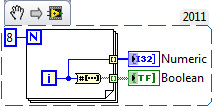
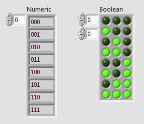
I am in the course of generations bit 3 digital using 9403 digital module and cRIO 9014.I signal must generate all combinations from 000 to 111.la so I have to give the Boolean constant either true or false 9403.I output module'm not gettimg how incrase step value of 000 001 and so on... Should I use the shift register?
I know how to use the registry to offset for integer value bt I don't hv any idea on the Boolean value.
in the hope of solution...
Here is a small example that uses the number to array of Boolean function. The digital indicator has its display of the binary value (%b) formatting.
-
I can read two-channel USB-6008 using THE Signal Express?
Hello world!!
Is possible to read the two analog inputs at the same time?
Example: Using Signal Express, I need to read the (channel 0) analog input and analog input (channel 1) at the same time.
I try this but, the signal on purpose gives me an error message saying that I can't read several channels at the same time using the USB-6008.
Is this true?
Thank you
Ivo João
André,
Grato definition of pela.
SUA ajuda muito util faith.
SDS,
Ivo João
-
How do you take into account a differential signal with daqmx?
I created a channel using 2 separate power sources. However, these sources of tension are two differentials through other channels on the DAQ card. Is there a way to put my physical as something like channels ' premium w / channel xxx "?
No, the differential pairs on DAQ cards are wired. Usually 0-8, 1-9, etc., but that depends on the map. Read the manual of your specific device.
-
generation of carrier multi using vector signal generators OR
Dear all,
I have a client who asked me about the capacity of the vector signal generators OR to generate signals porters multi, and if yes, what will be the minimum displacement between adjacent channels? There already buy a complete RF PXI system of NEITHER and I need to support as soon as possible
also, if I can work on the 2.7 GHz or 6.6 GHz to test GSM and CDMA2000 1 X RTT units?
can someone help me in this please
I'm in a hurry!
Mohammed,
Since VSGs of NOR are all software based, you can generate practically any signal you want, as long as it is within the bandwidth and dynamic range of the instrument. The SMU-5672 generator has a bandwidth 20 MHz, and the SMU-5673 real-time has 100 MHz of bandwidth of generation. You can create your MULTIPORTEUSE waveform in software and set the way you want.
Each platform is able to test GSM and CDMA2k. I would recommend the platform 6.6 GHz for test times improved if it is for the production. Implementation of the Protocol can be a challenge, however. If you have a great opportunity cell phone, you should get in touch with your field sales engineer OR to see if EITHER can provide any help.
-
Can I use differential ground with PXI-6704?
The answer is no.
I spent most of the day on the phone with engineers of NOR. The PXI-6704 manual provides conflicting information. Indeed, the PXI-6704 that she "can connect to a load that has a floating ground" operator, but it should also be mentioned that the load will no longer a floating ground, because the planes on the ground of the device are connected to the signal ground of the computer, which is connected to the Earth System. I don't know why the verbiage on floating to the ground is included because there is no way to isolate the load with this device.
Our team regained the PXI devices OR. We have worked with the Application engineer spoke to R & D of clarification in the manual.
-
How to use a signal of true/false dynamics with a business structure?
Hey everybody-
Is it possible to enter a case structure dynamic data of true/false? We try to generate a waveform and want our structure case to run when the wave exceeds a certain threshold value and freeze execution when it drops below the threshold (If false). However, we want the case structure to run continuous - i.e. If the structure of the deal for the 'real' case running while the waveform is above the threshold, we next want to deal for 'false' structure to run when the wave goes below the threshold, and so on until we stop our program.
Any suggestions would be much appreciated!
Rachel
Remove the loop around your DAQ Assistant vi express (I hate express screws). There is already a big loop around all of the code in the lower part. As has been pointed out by Ravens Fan, don't assign continuous acquisition. Set a finite number of acquisitions. Then the rest of the code can run and the loop can travel again.
Get rid of the stop sign at the top. When the code is finished, Labview will stop on its own.
You have two stop buttons. Only one is necessary. Look at my example posted a few messages back. A STOP with local variables.
Shrink your block diagram. It takes more than one monitor space. It is difficult to read when you have to scroll all over the place.
Maybe you are looking for
-
I get a message on my watch "Device locked" Unlock iPhone to start using Apple Watch "so I have the odd from my iPhone, now I can't pair it again.
-
Can I recover files after a permanent removal?
QUESTION: I need to recover my Rhapsody music library that seems to be permanently deleted. PROBLEM: The user ignorance/stupidity. I tried to make room on my hard drive and I seemed to have 2 copies of Rhapsody. Oops. I believe it should be possible
-
Hello, reset a couple of computers for my friend we have Windows 7 and I reset than a fine. But the other has Vista x 64. I'm looking for a Windows ISO file for this. But I don't want a factory of ISO recovery because that will be a lot of bloat ware
-
Impossible to install Windows 10 keep getting error 08009000F - 0 X 90002
Can not install windows 10 am getting error 08009000F - 0 X 90002
-
Parameters of system tray icons keep the reset after reboot
Hello My system tray icon settings are lost whenever I restart my laptop. I tried to reset all settings, I tried to install the experimental fix Windows6. 1 KB979155-x 64.msu nothing works. I also tried the following registry settings that now I have