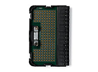
measures 16 differential signals
Greetings from the Argentina!, I use an NI USB-6218 box for measure 16 analog floating aboutthose, in differential mode. I have a practical problem, to avoid erratic results, I have to use 2 resistors of polarization to THE GND for each signal, which means that I need 32 resistance!, we chose this ADQ unit because we need a system compact adq but use all this if resistances not practical at all. You have a more simple solution?, is there any accessory sources which includes resistors to GND?
Thank you and excuse my English...
a bit of these will keep it nice and tidy
Tags: NI Hardware
Similar Questions
-
create the differential signal of 6289
Is is possible to create a sine wave of differential on the output of the 6289? And how can I do this.
I created a differential DC 1V AO0 positive and negatives 1V AO1. Then measured on a differential input ADC signal, which is my DUT.
Now, I'm cutting the CMRR and wanr to use the DAQ6289 because I don't want to add another piece of equipment for the test plan.
Any ideas would be appreciated.
Please take a look at this example to see how to generate out of phase sine waves:
http://zone.NI.com/DevZone/CDA/EPD/p/ID/5001
Have a great day!
Daniel G.
National Instruments
-
NIDAQmxBase uses differential signals?
I recently updated the NIDAQmx Base to the plus version and. But now I'm a horrible corruption of my signals. I checked with a scope and the signals are correct, but it sounds horrible crosstalk between channels. The only thing I can think is that the Council does not truly differential switching beyond the first 8 channels.
I use a card of 64 channels so there are 32 differential channels, I'm only using 16 channels beginning. I use ' Dev1 / ai0:7, Dev1 / ai16:23 "for the specification of my channel. The equipment works as the default "Datalogger" shows the correct data. But I'm guessing that the data recorder was built with an earlier version of the basis of NIDAQmx. This seems to happen when you use more than the first 8 channels. This VI allows to work with the previous version of NIDAQmx base.
Is this a known issue?
Here's the code to initialize the jury NOR-6033

Mac OS X 10.4.11 PPC / LV 8.5.1 / NIDAQmx Base 3.2.0 / VISA 4.4.0
Hi Scott-
I agree that relocation is the most appropriate next step. I tried here with a very similar setup and I could get the correct number of samples during my reading, and accurate data looked. Please let us know your results once the reinstallation completed. Thank you-
Ed
-
Measurement of differential tension for voltage range 0-20 V
I'm trying to understand the best way to measure the internal tensions in a pile of electrolyser containing 10 cells. Voltage range is 0 - 20V, with each measure 0 - 2V voltage differential. I know that each module on a NOR-DAQ (6218, 6210, 6009, etc.) can not see voltages greater than 10V. If I use the AISense or the second Chamber of the ground to the high tension of the first 5 cells (~ 10V), I will damage the Board or which will allow me to reach the upper limit of 20V of the system. In addition, I need to be able to measure the voltages at the same time.
If there is a piece like hardware or the Commission on this topic, please let me know. I write on the multifunction DAQ card because it is the material that I am familiar(-ish) with and that's what we have at home right now.
Hi sbrawn,
I recommend reading the high voltage and DevZone isolation measures.
If you are looking for a DAQ hardware that has a range of over 10 V voltage, I recommend searching the catalog of products here.
-
Repeated values in the measure (FPGA, cRio) signals
Hello
I'm seeing repeated in my measurements values and trying to determine the cause
I read a single analog channel from a module NI 9201. In order to eliminate the noise, I averaged several samples by using the ms and RMS measures VI (shown in "FPGA Code.png")
An example of repeated values appear in the "comparison of Signals.png' for both the original signal and mean
The sampling frequency of the NI 9201 module for a single channel is 500 kech. / s, which I also checked by measuring the sampling frequency (the code for this is also reflected in "FPGA Code.png")
On the target of cRIO RT I record these values in a loop timed 500us using 1 MHz of the cRio clock
For the ms and RMS measures VI, I tried several options, for example:
-500 US measurement time, sample rate 500 kech. / s
-450 US measurement time, sample rate 450 kech. / s
-400 US measurement time, sample rate 400 kech. / s
-US 300 measurement time, sample rate 300 kech. / sEach of them give measurements with repeat values to varying degrees, for both original and average signals
Any suggestions?
-
control valves to match a level in a supply tank (measured by differential pressure)
Hello world
I'm trying to regulate the level in a supply tank by opening or closing the tap of the tank of pure solvent above it.
To check the level, I have a differential pressure transmitter connected to the computer.
So when then the level is below a certain value, I would open the valve at the top with a pure solvent, and when the level exceeds this value, I want to turn off the tap (the level will go down because the system is running and do a permeate.
The valve and the DP transmitter are connected to the computer via USB. Valve: Omega-3-PSV, signal of 0... 20mA
I tried different ways, but it does not work.
I am a beginner with labview...
Thank you very much for your help
See you soon
Florian
A screenshop, of the part of my program I was talking about!
I hope this will help other users!
-
Measurement of respiratory signals by Pulse Oximeter
heHi, it comes to Madhusudhanan Natarajan Anjalai Ammal Manguin Engg College, Kovilvenni. I would like to ask a few questions related to the DAQ products. In fact, we will update the Oximeter research in sleep, surveillance system. To do this, they gave certain requirements. * To interface a Pulse Oximeter (sensor) to the above, said including hardware DAQ. * The Oximeter is used as a sensor and the analog signals respiratory entrants that must be converted into a form of (digital) analogous to the means of acquiring data. Further process will be using NI LabView. Is there any Interface of system Acquisition of specific data for the above? In addition, to monitor respiratory signals. How to display the above? (Normal and abnormal breathing) Please give me the above specifications.
Kind regards
Madhu.
Madhu,
What exact Oximeter do you use?
You can specify is your Pulse Oximeter output analog or digital signals. Some useful information are what frequencies it exports, what tension? What kind of resolutions did you?
Danny Funk
Application engineer
-
Can I use five differential signals analog usb 6008?
Hello!
I have the USB-6008 housing with one and two potentiometers temperature sensor (and one meter and digital input is also beign used).
I've only got analog +-left slot but I still need to connect the voltage and current signals of a diet. Is it possible to have both connected somehow to the last + slot?
If it is not possible what harware would you recommend instead of the 6008?
6211 next best step up that gets you more AI.
Alternately, you could just put a 2nd 6008 in the system... certainly cheaper than a 621 x.
-
How do you take into account a differential signal with daqmx?
I created a channel using 2 separate power sources. However, these sources of tension are two differentials through other channels on the DAQ card. Is there a way to put my physical as something like channels ' premium w / channel xxx "?
No, the differential pairs on DAQ cards are wired. Usually 0-8, 1-9, etc., but that depends on the map. Read the manual of your specific device.
-
Have we not measures of differentiation of discrete elements / request executing MRP
Hello
We have a point to Make (Finished Good). For the same article, we created MDS & MRP but when we supply and demand to release, we have only good requisition/None/work order as Option AS, nothing associated with discrete IMPLEMENTATION. appreciate your response where he could went wrong.
in the preference we choose discrete as job class as well.
Thanks in advance
Wanga
Wanga,
Work means quiet work.
I hope this helps.
Kind regards
N
-
How to measure differential analog signals
I read the hand signals and measure single-ended and differential, but I still don't know if a method is appropriate for my applications. Basically, I connect a BNC to one of the analog channels. The NLC has the real signal in a single thread (internal male) and land in the other thread (external shielding). I connect different components to different analog inputs so that they cannot share the same field (or the negative terminal). What is the best way to acquire this kind of data. It seems incremental settings on Panel (BNC-2090) different records between, say, ai1 and ai9. I don't want that because I want to record the difference between the two wires that are connected to the ai1.
Who said that a differential signal is connected to two different BNC? You need to look at the manual? The diagram in figure 2-2 is quite clear on the connections on the way in which the shield is connected in differential mode.
-
Balanced circuit differential measurement
I remember back to Labview 5 national had a great discussion tutorial white paper or knowledge base on how to understand the values of resistance when you perform a measurement of differential circuit. I have a PXI-6230. I can't find that anywhere now. Can someone point me to a discussion of the decent webpage on the calculation of the resisitors to differential measures?
Thank you... Clint
Hello
Please visit this link under the title "floating (nonreferenced) sources of measure."
Wiring and considerations of noise for analog signals
concerning
-
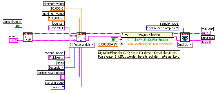
signal level for pulse width measurement
Hello
I am able the pulse width with the meter M6251 (CI pulse width)
I understand that the digital input works on the TTL levels (0, low 8V 2, 4V high).
Can you say exactly in which the level of signal pulse width is measured?
Thank you
Ralf
In fact, the transition from low to high (or vice versa) is located in between 0.8V and 2.2V. It is not specced exactly where it will be (although you'd be able to get a better idea, if you have an analog source, you can slowly increase until you see line status change).
This is why the fast rise time are important to accurately measure the digital signals.
Best regards
-
How can I measure the voltage of a signal?
Well!
I'm trying to read the voltage of a signal using acquisition data PCI-6229 card.i am giving the signal as an input to the DAQ card and try to read the voltage level. The range of my signal is 4.8 ~ 5.5 VDC but the results are not accurate, such as measured with DMM. My code is as follows:
1.i m using DAQmx create channel to create an analog input channel
2. then a sample clock with finite samples, sampels by channel and set the rate of iteratively
3. then I start the task
4. analog playback 1 DBL AK1 N sample d
Pressure readings I am differs widely that the actual.e.g a signal measured with DMM is 5v but when applied to the DAQ hardware and measured gives 6v.also I have to define minimum values and maximum in VI... If I put 4 to 5 maximum and minimum to measure a 5vDC signal it gives good result. , but if I change the maximum setting to 6v then it gives me results.also bad behavior is different for different signals for example when I measure a 6.5 VDC to signal that it shows me the voltage as 7.3V...
Photo of my code of VI is attached... Please answer... or give me another code that works fine at the voltage of a signal reading.
-
Align the two signals and measure the Phase Shift
Hello
I do an experiment in which I use the NI USB-6221 DAQ card. The jury is able to make 250 k samples/second. I want to measure two voltages in a circuit and find the phase shift between them at frequencies between 1 and 10000. First I ouputted a wave sinusoidal frequency variable through the Commission and applied to a test circuit. Then I used the Board to measure the two tensions consecutively (thus reducing the maximum sampling frequency at 125 k). I used the signals align VI and measured the two phases and then calculates the phase shift (VI attached in Phase 1). It worked well for the test circuit I built in which the phase shift went way logarithmique.20 degrees ~84.5 degrees and then stabilized. At frequencies above 5 000 Hz phase shift must have remained constant, but it varies more or less 1 degree. When the phase shift is 84.5 degrees, present a degree of variability is not particularly explicit. When I asked my program on the circuit that I really wanted to measure, the phase shift went from-. 5 degrees up to about 1.2 degrees. The change in the values of phase shift at high frequencies (> 3000) was environ.2 degrees. Given the small phase shift, this variation is unacceptable. Now I tried to use a sequence to each blood individually (increase the maximum sampling frequency to 250 k) and then align the two signals and measure the phase of each shift. When I use align it and re - sample Express VI to realign the two signals, I get the message "error 20333 analysis: cannot align two waveforms with dt even if their samples are not clocked in phase." Is it possible to align two signals I describe here? I enclose the new VI as Phase 2
Matthew,
I think I have an idea for at least part of the problem.
I took your program data and deleted stuff DAQ. I have converted the Signal on the chart control and looked then what was going on with the signal analysis.
The output of the Waveforms.vi line has two waveforms, like the entry. However, arrays of Y in the two waveforms are empty! It does not generate an error. After some head scratching, reading the help files and try things out, that's what I think is happening: the time t0 two input signals are 1,031 seconds apart. Since the wavefoms contains 1,000 seconds of data, there is no overlap and may not align them.
I changed the t0 on two waveforms are the same, and it lines up. The number of items in the tables is reduced by one. Then I increased the t0 of 0.1 seconds on the first element. The output had both greater than the entry by dt t0 t0 and the size of the arrays was 224998. Reversing the t0 two elements shifts the phase in the opposite direction.
What that tells me, is that you can not reliably align two waveforms which do not overlap.
I suggest that you go to 2-channel data acquisition and that it accept the reduced sample rate. You won't get the resolution you want, but you should be able to tell if something important happens.
You may be able to improve the equivalent resolution by taking multiple steps with a slight phase shift. This is similar to the way that old oscilloscopes of sampling (analog) worked. Take a series of measures with the signal you are currently using. The make enough average to minimize changes due to noise. Then pass the phase of the signal of excitement to an amount that is smaller than the resolution of phase of sampling rate and repeat the measurements. Recall that I calculated that for a 5 kHz signal sampled at 125kHz, you get a sample every 14.4 degrees. If shift you the phase of 1 degree (to the point/mathematical simulation), you get a different set of samples for excitement. They are always separated by 14.4 degrees. Take another series of measures. Transfer phase another degree and repeat. As long as your sampling clocks are stable enough so that frequency does not drift significantly (and it shouldn't with your equipment), you should be able to get near resolution of what you need. The trade-off is that you need to perform more measurements and may need to keep track of the phase shifts between the various measures.
Lynn
Maybe you are looking for
-
El Capitan on a Macbook Pro for mid-2012?
In other words - my OS upgrade needs badly. Slowdowns of Safari and page gel side, I start to have problems of compatibility. I stuck with the Lion of the mountains (OS X 10.8.5) for a while now, and as much as I love him, I decided that I have to up
-
This copy of Windows is not genuine after updating Windows 10 and return to Windows 7 Ultimate
When I've updated to windows 10 using the windows icon free 10 in the corner, it didn't appeal to me, so I used the button restore to go back to windows 7. After he turned back, a saying watermark "Windows 7 Build 7601 this copy of windows is not gen
-
what I do when im missing any .dll?
says im lack vcomp100.dll and don't know what to do.
-
BlackBerry Smartphones trying to connect with the desktop software for my blackberry
Hey, M trying to connect with the desktop software for my blackberry torch 9800 and it asks password for the connection. I am using same unlock password I use for my bb but for desktop sofware it shows incorrect... pls help!
-
Before that I think begins with my post, here is the information about this: HP Pavilion dm4-1165dx www.PCMag.com/Article2/0, 2817,2371216, 00.asp #fbid = xXc-6Rw02ZI There it is. There is also a link to see more information. My computer got this pro