Nonlinear worthy of the equations of the diode
Hello
I want to make an adjustment not length of the features of diodes.
The function that I need to set up is could be written as Y = f (X, Y).
This means that the data is both the goal of adjustment and a part of the equation.
Is this possible with the vi made nonlinear of levenberg-Marquardt?
Best regards
Baptist
OK, I understand.
I ' l try tomorrow morning.
Best regards
Baptist
Tags: NI Software
Similar Questions
-
Read a resistance of the diode by vs NI USB multimeter
Hello
I read a resistance of the diode at some entrances to supply voltage
and I found that
to 0.2 V
the value of resistance by NI USB-6212: 200 ohms
the value of resistance of meter: 2 kohm
0.5 v
the value of resistance by NI USB-6212: 500 ohm
the value of resistance of the multimeter: 5 kohm.
Could you please let me know why the values are different by 10 times?
Thank you.
No - we can't measure the resistance in this way.
To measure resistance, you normally spend a current known and then measure the voltage. A DMM will be repeated by generating a little known current and measuring the internal tension. If you provide an external voltage thus, DMM internal resistance measurement will not work.
For the LabVIEW - The USB-6212 can measure the tension. If you want to measure resistance, while the unit is plugged, you need to know/measure current (for example through a shunt resistance) and the tension and then do R = V / I for the resistance. I don't know what the argument of type 6212 if you try to perform a measure of 'resistance', as it is not a source of internal current.
Oh, I thought that this all seemed familiar - here's a similar thread: https://forums.ni.com/t5/LabVIEW/daqmx-resistance-measurement-6251/td-p/3267084
-
"Not worthy of the mechs found" what does mean
macOS: 10.11.5 (El Capitan)
Mail: Version 9.3 (3124)
Three e-mail accounts
iCloud
SKY (my ISP in the United Kingdom)
Nearly host (Reseller Hosting UK)
Earlier this year nearly HOST made me change my SMTP authentication to look like

When we look at another problem of Mail, I noticed the following messages that appear every few minutes in the syslog.
There is a configuration issue with my system?
I can't ignore the syslog messages?
Example of syslog messages
17 Jul 19:18:53 mini Mail [5562]: no worthy mechs found
17 Jul 19:21:01 mini sandboxd [184] ([5562]): Mail (5562) deny com.apple.cache_delete mach-search
17 Jul 19:23:32 mini sandboxd [184] ([5562]): Mail (5562) deny com.apple.cache_delete mach-search
17 Jul 19:23:34 mini sandboxd [184] ([5562]): Mail (5562) deny com.apple.cache_delete mach-search
17 Jul 19:23:53 mini Mail [5562]: no worthy mechs found
17 Jul 19:28:53 mini Mail [5562]: no worthy mechs found
17 Jul 19:28:53 mini Mail [5562]: no worthy mechs found
17 Jul 19:33:53 mini Mail [5562]: no worthy mechs found
17 Jul 19:38:53 mini Mail [5562]: no worthy mechs found
Jul 17 19:43:43 mini Notes [8906]: {'status': '400', 'plans': 'Carrier', 'field' ': 'https://mail.google.com/""}
17 Jul 19:43:53 mini Mail [5562]: no worthy mechs found
17 Jul 19:48:53 mini Mail [5562]: no worthy mechs found
17 Jul 19:53:53 mini Mail [5562]: no worthy mechs found
17 Jul 19:58:53 mini Mail [5562]: no worthy mechs found
17 Jul 20:03:53 mini Mail [5562]: no worthy mechs found
Jul 17 20:13:43 mini Notes [8906]: {'status': '400', 'plans': 'Carrier', 'field' ': 'https://mail.google.com/""}
17 Jul 20:19:52 mini Mail [18155]: CFNetwork SSLHandshake failed (-9807)
Jul 17 20:19:53 mini Notes [8906]: {'status': '400', 'plans': 'Carrier', 'field' ': 'https://mail.google.com/""}
17 July 20:27:20 mini Mail [60503]: not worthy mechs found
17 July 20:30:27 mini Mail [60503]: not worthy mechs found
17 Jul 20:35:27 mini Mail [60503]: no worthy mechs found
17 Jul 20:38:06 mini Mail [60503]: no worthy mechs found
17 Jul 20:38:40 mini Mail [60612]: no worthy mechs found
I can't ignore the syslog messages?
If Mail works, Yes.
-
HP ENVY 17-k252ur: pilots not worthy of the HP ENVY 17-k252ur
Upgrade Windows 7 x 64 system. Wireless and network driver download. Message - the drivers are not installed properly. Network cards do not appear. Internet does not work. What should do? Where to take the normal driver? The rest of the drivers has not even tried to install.
Неlp me, please!
Solved!
-
BlackBerry smartphones how long is the diode flashes when we receive a new message?
I feel that sometimes my blackberry light no longer blinks...
Sometimes it does not blink and I have new messages...
Why?
Concerning
Hi and welcome to the forums!
You might be interested in BB alerts. This program will allow you to
extend the alert indicators on your BB. See more information
on the link below. There is a trial period.
Thank you
Bifocals
-
CTRL/0 gets "worthy on the screen", but that it reverses?
I use CS3, but I think it is the same in other versions.
View > Fit on the screen (or Ctrl + zero) works very well. But how you go back to the previous state? CTRL + Z does not do
Window > arrange > new window, set it to adjust the screen and then close when you are finished with it. If you do a lot, do an action of it.
-
transistor for my diode-transistor vi equation
This is a diode and transistor vi. You can change transistor/diode under the graph. in the block diagram of the diode you will see that it uses an equation for the current. I put an equation and create the schema for the transistor also so I can see the curve in the front panel, but I can't seem to find what equation I put! does anyone know what equation works?
-
Import the SPICE model for transistor BJT BFP720F in Multisim
Hello
I'm trying to get the SPICE model for the BFP720F transistor provided by Infineon to work in Multisim.
I have attached the template as provided by the manufacturer.
If I import it as-is, I get error messages "invalid node identifier '<4>'" (I have translated that German, it might not be exactly this message in the English version).
So I tried to replace all the "<4>" with "4", which seems to help, but now the error is "adjusted temperature setting"VJC (PC)"negative" and "incorrect use of the parameters of the model. Now I don't really know what to do with it.
Is the template provided in the wrong format? I somehow can it in the right so I am able to use it?
Because I need for my project semester in College, any help would be much appreciated.
Thanks in advance!
Hi NikoNR,
When writing a detailed description of what I did exactly with the Wizard component, the component again to create in Multisim from scratch, I found that there are different SPICE models provided in the package for use with AWR MWO. They have a different file extension, but are normal text SPICE inside files.
It turns out that they actually work with Multisim. The difference is small, there is only one temperature (TNOM) setting that is absent in these models, distinct from the "general" I first tried to use. It seems that Multisim had a problem with this setting, leading to the error I encountered.
Anyway, the problem is solved now. Thanks for your help

Good day
(The now much happier) EE-student
----
Edit: I have attached the SPICE model, that I ended up using, in case someone at - he never met a similar problem. The only change I did this, is to replace '<4>' with '4' in the part of the diode (single occurrence here). I had to zip to download with his original extention (.mdl).
-
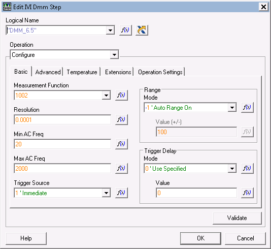
Appropriate use of the specific functions of IVI Driver
Hello
I have to call niDMM driver specific functions, for example the diode test function and source of current value. I am able to do using IVI step types. I just input function and the ID attribute of the niDMM header files. I would use the IVI drivers, but I need the specific functions of the device in some applications. I tested it and it works well, but is it the right way to do it? What is the recommended approach?
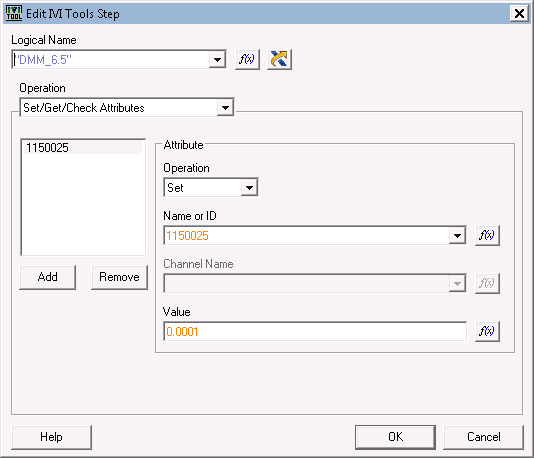
My IVI not look like this when usig own functions and attributes: I don't like typing in numbers, but I've not found a way to use the header file definitions (see below).
Diode test ID is defined by nidmm.h:
#define NIDMM_VAL_FUNC_SPECIFIC_EXT_BASE IVIDMM_VAL_FUNC_SPECIFIC_EXT_BASE
#define NIDMM_VAL_DIODE (NIDMM_VAL_FUNC_SPECIFIC_EXT_BASE-2L)
defined by IviDmm.h
#define IVIDMM_VAL_FUNC_SPECIFIC_EXT_BASE (1000L)
Current source attribute ID is defined in nidmm.h:
#define NIDMM_ATTR_BASE IVI_SPECIFIC_PUBLIC_ATTR_BASE
#define NIDMM_ATTR_CURRENT_SOURCE (NIDMM_ATTR_BASE-25L) / * ViReal64 * /.
ini.h:
/*****************************************************************************/
#define IVI_ATTR_BASE 1000000
#define IVI_ENGINE_PRIVATE_ATTR_BASE (IVI_ATTR_BASE + 00000) / * base for private motor IVI attributes * /.
#define IVI_ENGINE_PUBLIC_ATTR_BASE (IVI_ATTR_BASE + 50000) / * base for the public attributes of the IVI engine * /.
#define IVI_SPECIFIC_PUBLIC_ATTR_BASE (IVI_ATTR_BASE + 150000) / * base for specific drivers public attributes * /.I prefer to use a code module and call the NIDMM functions in there. You can use the type rather than the identification number definitions.
-
Control the time times of high and low of trains of pulses in C++
Dear team of support of National Instruments,
Here's what I have so far:
I was able to generate the number of pulses (a pulse = a rising edge and front descending one) that the user has indicated via the GUI I created in Visual C++ 2008.
I use DAQmx 8.6.
I use the DigitalSingleChanWriter (hopefully, that's what it's called).
I use for the synchronization of the sample, on request. I tried to use all other types of calendar but I always get a DAQException run the error that says I can use only OnDemand calendar.
OK, so here's the problem:
I have a USB-6008-6009 card connected to an oscilloscope. I know that the connection is correct, otherwise nothing would appear. However, if I send say... 6 impulses, the delay between the first rising edge and the first falling edge is dramatically different and then the second and the third. If I return my samples, I get an assortment of new and totally random times. So finally, my question is "Is there a way to control the time of a great time and a bit of time?"
I use a Compaq 2003 lap top, what is worthy of the rubbish heap. I'm not to blame on this right away as problems that will not solve the problem at hand. Although I understand if it's actually the problem for random times, but I would still have no way to control the time themselves.
I hope that I don't have drug it too long, but I decided that distribute information on would be better then just a few tid bits.
Thank you for support, that you can offer,
Daniel
OK, so I just returned from the lab, and this is what I got:
I was able to control the time at the time of the high and low by using the "WriteSingleSamplePort" of the DigitalSingleChanWriter method.
I put it in a loop that repeated many times that the user wanted impulses.
At the beginning of the loop, I used a delay function that I wrote and delayed for a time given and then a pulse with a value of 255 and then delayed again and a pulse with a value of 0. And then restarted the loop.
In the end, it works.
Of course, I have another question. I kept reducing the amount of time between two pulses (1 s, .5s, .2us and so on). However, once I have diminished the time of secondes.01 or a millisecond, the pulses on the arrested oscilliscope becomes smaller. It seems that past 1 millisecond Board USB-6008/6009 is unable to deal with the exigencies of the moment. Or else the computer trash part on that I cannot deal with the exigencies of the moment. But I believe that the Council is not at fault because it was designed for this exact sort of thing, could you tell me if there is no limitation to the Commission which prevent production of pulses in or within a period of 1 millisecond. Thank you very much.
Thanks for all the help,
Daniel
P.S. I'll stop you buggin with big messages that I promise you.
P.P.S. If someone wants to see my source code for their own project, I'd be more than willing to share. Please email me or leave a message here.
-
How to protect the inductive tension peaks DAQ modules
I just ordered the USB DAQ 9221 module. He reads voltages up to 60 volts. My loads are inductive. I have been using diodes to avoid the negative peaks. I used a scope on one of the inductive loads with a diode. I have a recorder-560 volts. Led TV type is better? If yes how can I specify a part? I don't want to blow the DAQ module.
Thank you
Philippe
Philip,
It depends on. What is the source of your signal? What is the range of voltage and frequency of the desired signal? How it is coupled to the inductive loads? How fast are transients? The amount of energy they contain? What kind of grounding circuits you have?
The diodes are often good protectors. TVS diodes are usually specified and evaluated for transients, then the conventional diodes are usually assessed BOF functions of rectification. Some systems may require several protection devices chosen to complement each other. I have seen systems with discharge gas, MOV, diodes and crowbars tubes.
Lynn
-
I'm using a 1N4148 as a temperature sensor in a circuit of the thermostat (reverse engineering). I want to manually to set the temperature of ONLY a component of the circuit, either in the simulation is running, or default between simulation runs. The remaining components must remain at "nominal temperature.
I hope that the diode model will reduce approximately 2.3mV Vf / degree that I change the temperature. I tried the model change for the part, but there was no field to allow me to enter (for example) T_ABS)
Just, T_ABS is the template parameter to change. If you are using a version older than 11.0.0 Multisim, then you won't see this parameter in the model of most of the components of diode parameters table.
I wrapped a 1n4148 in a subcircuit so that you have access to plain text to the model, in which you can specify T_ABS in the .model statement.
-
9234 sensor back to resistance of the chassis
My question is about the NI 9234 module and terminal return (HAVE) resistance to the chassis. On the side of the module, the diagram shows a 50 Ohm resistor to the chassis. However, when measured using a multimeter, the resistance is much higher (order 500 kohm.) I hope someone might be able to explain this discrepancy. My only thought is that, based on the data sheet, there are current limiting diodes present between performance and 50 Ohm resistance that may have an impact on the measurement. I don't understand how it would be possible, however. Any help is appreciated.
Page 11 of the Manual:
http://www.NI.com/PDF/manuals/374238c.PDF
Watch back to back diodes in series with the 50 ohm. They are probably affecting your measure if your DMM does not exceed the voltage of conduction of them (don't know what the specs are on the diodes).
-AK2DM
-
How to hide indicators based on the values of the case?
I'm trying to show some of the indicators only if necessary - the derivative graphic when you test a resistance and the semi-log graph extracted to test a diode. I'm not too sure that I extracted the characteristic part of the diode with precision. (The few cases of structure is completely turned off to the right, everything else works.)
Thank you!
Here is an example:
the function of visibility is a simple bool
-
E/s and the issue of Communication for the sbRIO-9601
Hello
Our company is looking to use the sbRIO-9601 in an OEM application and I had two technical questions on the Board of Directors.
(1) are the functions VISA support? I saw there an RS232 port, I want to just make sure I can read/write easily out of it using prebuilt VI rather than do all the level low and starting from scratch.
(2) we will be reading and writing of simple commands to a device coupled via the RS232 interface and based on the response, illuminating an LED controlled by the Board of Directors. I have not selected any led and hoped that neither could provide some clarification on the limits of the power provided in the sbRIO-9601 user guide. We will use the 3.3V output... I should put a resistor in line current limiting or I can put the diode directly between the output pin and the digital ground? Us can drive more than 15 LEDs, however, we will never more than 3 see on at any given time. I saw in the 3.3V section i/o of the documentation that the current max tested per channel is 3mA... but bus total is 330mA. Is there a limit to how much we can provide each channel as long as we remain under the 330mA all together?
Thank you
Hi leachdor,
(1) VISA functions are supported for the RS232 port on the sbRIO, so do not do any level low programming for them.
(2) the maximum that we specify channel 3 is my. You can combine several channels in parallel to increase this output up to 330 mA for the total bus. Since you're only driving 15 LEDs and there are 110 channels of output, you should be able to combine some led.

Maybe you are looking for
-
How to remove search 10 iMessage iOS image history
How does one remove the iOS 10 iMessage image search history?
-
Mail cannot connect to Hotmail account. Why?
Before I was on vacation last week, my hotmail account has been working find on my icon of mail on my macbook pro and iPad. Since the return from vacation, I can not connect to my hotmail on these products account two apple. My iPhone 6 works find.
-
Is it possible to determine how much time is left on the Bluetooth headset?
-
Re: I lost the Flash Card function keys
Ive lost the flash cards used for the drop-down list at the top of the screen. Tried several different things, including updating the drivers from the Web site.At the moment, some of the function keys work ok, IE works brightness, lock - but the wire
-
error code 0 x 080070643 error code__0x800710D9
I have to uninstal windows Defender to download Microsoft security essentials? or service pack 3 for windows xp