Order of the blocks in LabVIEW
Hi all
I am a beginner in LabVIEW. I what is the order of execution of code in block diagram in LabVIEW. It is left to right or from right to left? or y at - it a preference for order as a priority higher than for loops or something like that?
Be a c programmer I think this way. Is it good to compare and understand Labview as well or is it a completely different architecture? Please correct my way to understand things if I'm going in the wrong direction as a beginner. I enclose an example of block diagram, perhaps you can explain with her
LabVIEW does not from left to right, up and down, forward/reverse or any other physical form on the block diagram. LabVIEW is a DATA flow programming language, and it is the movement of data that determines the order of execution. There is a section using LabVIEW called 'data flow programming model' that you should read. In the picture you posted, you will notice screw connected with their error in / mistake the son. These connections are often used to enforce the order of execution. Also, because of its Western heritage, entries are typically placed on the left side of a VI and exits on the left, then you will generally see VI placed from left to right but it's just for readability. If there is no data connection screws separated on the block diagram, they will be run in parallel.
Tags: NI Hardware
Similar Questions
-
The blocks integral labview 7.1 where is in labview 2010
Hi I have to integrate signals sampled. In labview 7.1 is well checked blocks for it. But where is the equivalent in labview 2010? I can't find.
It's my VI, I now
-
2 orders of façade with a control on the block diagram
Hi all
Is it possible to use 2 controls on the Panel before which order the same control on the block diagram?
In order to have a sort of parallel control.
Thank you in advance.
-
Hello!
I noticed that the continuous measurement and a project in LabVIEW 2012 Logging using chains instead of enums and orders from the queue. I wonder if there is a good reason for it?
Kind regards
Anguel
First, string vs enum debate is probably the version of LabVIEW vim vs emacs. There are good arguments on both sides, and I doubt that there is always a "winner".
A brief summary of our reasoning for the current state of the project examples:
- We used enums for the state machine because it is self-contained. A state machine will never tell himself to enter a State, he does not know. Knowing (as the programmer) all possible States with the help of an enum allows you to enlist the compiler in order to help us avoid mistakes to change the time (because you can't quite out an enum and LabVIEW can be said if you are not covering all cases to a structure of the case, etc..).
Enums provide greater protection and rigidity by ensuring all withdrew at the time of publishing. This is often the 'default' recommendation that we do.
- We used strings for messages in queue manager because the producer of message and the message handler could be independent processes that are reused or traded. Channels avoid the need for the compiler to be able to connect the orders and push this responsibility to the programmer. This allows you to develop some sub-components independently as long as you agree to a series of channel commands that you can manage - you need not to share a file 'messages.ctl' or 'states.ctl '. It is conceivable a loop of message management a message it does not, how you can decide to either silently ignore it or will trigger an error (as we do in the model). The strings make it also easier if you want to swap the queues of LabVIEW outside by a TCP implementation for network vacilitate or intra-Processuse communication where the other end may or may not be written in LabVIEW.
Channels to provide more flexibility (that is, you can add new commands to an existing via plugins system, you can pass parameters as part of the string, etc.) at the expense of pushing her potential errors at run time and to put more responsibility on the programmer.
- The actor's gifts frame a 3rd option - using classes such as messages. For me, it combines many of the advantages of these two enumerations (strictly typed, change errors) and strings (flexible and scalable), but with the disadvantage of being somewhat less transparent (you understand OO, be comfortable to navigate through a multitude of screws, legacy of understanding, etc.).
I don't know there are other reasons, others to the breast OR had or seen as we validated models and examples of projects in-house, but here are my reasons. We know that we can not design for each situation there - our goal is to get useful models against new users to make them aware of what well thought LabVIEW programs are similar to experienced users know their applications better and I hope they do not hesitate to change what we provide or create their own designs, when they feel it's necessary. (On a side note, please share what you come up with - a community of experts sharing models would be really useful to us all LabVIEW users).
Best regards
Simon
- We used enums for the state machine because it is self-contained. A state machine will never tell himself to enter a State, he does not know. Knowing (as the programmer) all possible States with the help of an enum allows you to enlist the compiler in order to help us avoid mistakes to change the time (because you can't quite out an enum and LabVIEW can be said if you are not covering all cases to a structure of the case, etc..).
-
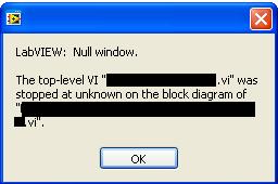
LabVIEW: Null window... stopped to stranger on the block diagram
Hello
I have a pretty important program that has been written in Labview 6.0. Recently, we have upgraded to Labview 9.0 and this program has been exported to an executable file with the new version.
When you run the executable file, I sometimes have the following error as seemingly random places. I was not able to crash when not to use the executable file. LabVIEW: Window zero. The first level VI ".vi" stopped to stranger on the block diagram of ".vi".
I apologize for having empty on the names of vi, but I can't give names of vi, say what is the software or code. I can tell it uses NI USB-6212 IO cards, interfaces with the instruments of Rhode and Swartz and uses a lot of file i/o.
I was hoping someone could give me a hint on how to debug such a mistake. I noticed that when this error occurs, the memory usage almost doubles.
Thank you
James
-
In LabVIEW 2010, I have a Def Type control i.e. a Cluster with several other controls within the Cluster. Apparently, the references to the controls in the block diagram are based on the order that the controls have been added to the Type definition command. The side effect of this is that if a control is removed from the command of Type definition, many of the done Variable reference in the block diagram or now either broken, or worse still, refer to wrong control in the Type definition. These problems are quite difficult to find and fix.
Comment: If you create a control of Type definition and make a Cluster. Now add any controls to the Cluster in an order, let's say A, B, C, D. Their types does not matter. Now use the Type definition in one or more controls on the front panel. In the block mark references to controls inside the Type Def would control on FP. Now return to the Type definition and remove the command B of the definition of Type. Now, lots of errors appear. Broken links. But worse still, you see old references to B that now refer to C and old references to C are now referring to the old references to D and D are removed altogether, etc.. This side effect is much more errors, broken links and misreferences than expected otherwise.
How add and remove controls anywhere in a Cluster in a Type definition, at will, without creating a whole bunch of errors in program, broken links and misreferences for controls in the Type definition that have not changed?
-
Problem of sync Tungsten E2 to the exchange of data of the order of the day
Hi guys,.
I am a pretty old used PALM devices, I have a Tungsten E2 that starting yesterday now not able to sync my PC more with any pf. I tried with Win 7, Win 8 using the Desktop 6.2 via Bluetooth using the HotSync Manager.
When I try to sync - upward, HotSync manager activity seems to be ok, the computer ask me the password I type and then the synchronization process starts, number of clicks green confirms the good performance of sync files syetm but when synchronization try to drive the agenda, he's missing, I mean that he doesn, t go more.
In my opinion, it seems that some data in your handheld pointer has changed and so that data from the agenda of the handheld to the PC is blocked. Unfortunately, I can't check with cable USB WIN 7 and 8 do not work with USB.
No idea how to fix this without losing my data?
Thanks in advance
Maurizio1960
Hello and welcome to the HP support community!
PalmOS devices have been able to sync via a USB cable for Vista64, Win7 and now Win8 for quite a while now. We have a post sticky implemented in the top few positions listed in this section:
The data of the order of the day is updated on the computer in Palm Desktop? Run the auditor of the Palm Desktop on Tools/Options/tools database to see if something needs to be repaired, then set the conduit Hotsync next to the order of the day on "Desktop replaces the handheld computer."
As usual, we recommend that you install NVBackup on an SD card before risking the loss of personal data. It can be copied to the card, the card inserted in your Palm and a full backup made and saved in the card. NVBackup can be found at www.freewarepalm.com.
Another suggestion would be to install DBFixit of Pimlicosoftware.com. It is designed to fix data errors, some free, others require pay a registration fee that goes to a sanctuary for gorillas.
WyreNut
-
Problem creating entries, exits and text in the block of Script Scilab
I recently installed the Labview with Scilab gateway. I'm under Labview 11.0 and Scilab 5.3.3. Files example executed correctly, but when I try to set entries or exits, there is no option to add ports. The block ignores also any text I type in or copy to it. I tried this on a white vi.
-
Change to error in the export file in the order of the elements in the array of construction
Hello world
Some time ago I wrote a vi file that performs the following operations:
As a first step, it initializes a camera and chooses a region of interest (ROI). Data on the return on investment will be eliminated.
Then he raster scan engine stage in x and y axis, in bidirectional mode (meaning that x alternating between sweeping left to right and from right to left as is inreased).
For each point of the analysis, the spectrum is collected, which is then integrated into lambda to give an idea of the total intensity.
Then the intensity is plotted, as well as the spectrum at each point.
The final results are exported to a text file.
The problem:
If I reverse the order of the son in the 'build' table prior to exporting the file, place the Total Count (intensity) wire instead of thread of the spectrum, the export file fails. By "fails", I mean it's the .txt file contains characters that resemble Chinese!
Why is this?
I enclose my .vi, as well as two screenshots that show the problem.
Hooovahh wrote:
Such a small change, should not have such a strange result. I advise to use some debugging tools like highlight the enforcement tools, probe and breakpoint to see what data is when it runs.
The Source is in 2011. I see an opportunity and a potential work around certain things to try.
- take the following steps
- Select each stacked sequence right click and "convert flat sequence.
- Select each flat sequence and delete the sequence
It could simply fix it by itself you want to turn auto-growth on surrounding structures
2 allows to observe the data in the table build
- For all wires that are sgl heading construction table insert a dbl and a copy of Allways
What I suspect LabVIEW is incorrectly re-use of buffers for the inhabitants of sequence
-
When I change the setting by LabVIEW on my device, I see change on the monitor of the device?
When I change the setting by LabVIEW on my device, I see change on the monitor of the device?
This question should be addressed to the manufacturer of the device. From your previous posts, I guess you use GPIB or serial. If the unit has received the order, the manufacturer should be able to tell if no indicators on the device to update when the order is received. Based on my experience, however, the device indicators will most likely update on receipt of an order successfully.
-
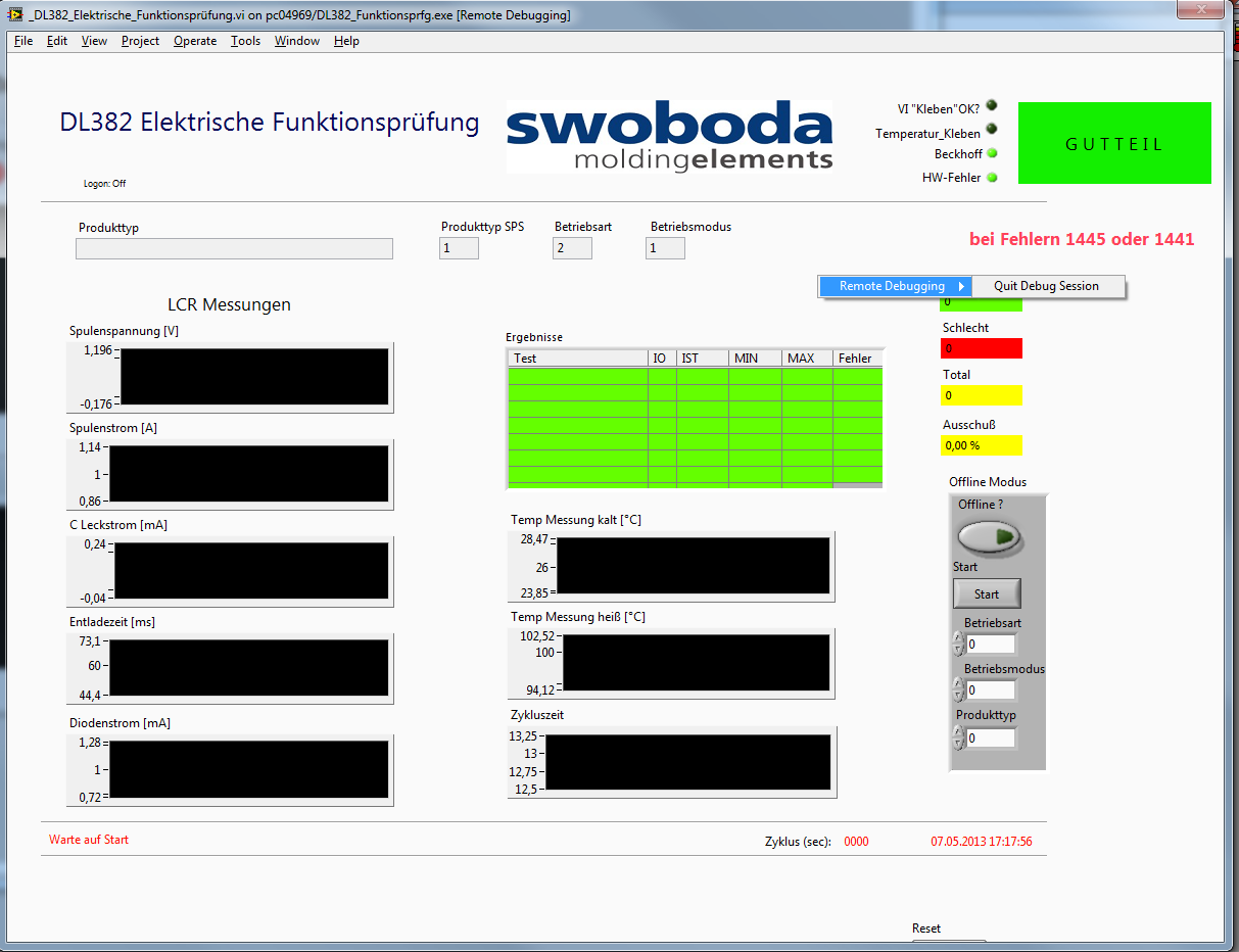
Remote debugging active but no access to the block diagram
I have an executable running on a target that I want to debug. I enabled debugging in the build properties, I enabled debugging in vi properties. I can connect from the development computer to the exe.
But the option to switch to the block diagram is simply not there (see photo). I know I am a first not who has this problem but I couldn't find an answer.
Without being able to see the block diagram, a 'debug function' is totally useless!
If anyone has an idea it would be greatly appreciated. Thank you
Hi peter,.
It is a known problem and a request for Corrective Action (130070 CARS) was created and reported to the Department R & D. looking at through the notes in the CAR, he must fix it in LabVIEW 2012.
Workaround solution: Debugging applications with menus on bar
-
order of the shutter with APT driver
Hello
I'm quite new to Labview. I want to remote control a SH1 shutter with controller of tsc001 within a Labview VI.
I have seen that we can use activex objects to insert a driver APT in a Labview VI (thorlabs drivers for control of the movement, see http://www.thorlabs.com/images/TabImages/GuideToLabVIEWandAPT.pdf, and http://www.thorlabs.com/tutorials/APTProgramming.cfm). Unfortunately, there are a lot of activex objects (APT Chopper / laser / motor / tec controls) but not the order of the shutter I need.
can someone help me please? Thank you very much
Damiano
Thorlabs gave me the answer, it's here if anyone should face the same problems: to communicate with a solenoid tsc001 control shutter use the activex MG17motor, instead of APTPZMotor. Then everything works perfectly.
D
-
Hi guys,.
I'm sure this has been posted in advice, but my search does not show good results.
I noticed in some messages that people could "join code" as an image. I've tried ctrl + c after have selected them
in the block diagram view, and then ctrl + v in the insertion code section. Is it thus you are supposed to
Do it? I uses a version of LabView 2012 assessment, would be - which is why it does not work?
Thank you
William
Select your code. Then go into editing-> create extract selection VI. This will create a png file that you can publish. Better yet, you can drag this excerpt on a VI and the code will automatically appear. It is a great tool.
-
What is the best way to keep the block diagram / cleaning of façade?
Hello
I'm relatively new to Labview so I'm not able to say if I'm overloading my programs or make my too crowded block diagram. I was wondering if there was some ways to tell if I can simplify my programming just by looking (perhaps only experience contributes to these things)?
I enclose my VI here. Currently, she is able to monitor the voltage and current of two engines. On the screen, you can see an indicator with the voltage and current values and there are cards that can display signals of different engines with a menu drop-down.
The façade is pretty clean, in my opinion of novice, but the block schema seems messy to me, just at the first glance. I foresee a problem occurring in the future however. In the future, I will have the VI to monitor 50 engines globally. All of the programming will be the same as the one I have now, but it will have 50 indicators and unfortunately 50 times just about everything. I would like to avoid this, but I don't know how I did.
I use a USB-6009. I use its four differential inputs to monitor the voltage and current of the two engines. In the future, I will get more units DAQ (25 in total because 2 motors can be monitored for each data acquisition). The new Renault will help will help with more resource space, but I think things complicate with the added option of 24 more Assistants of data acquisition (as used in my code).
Thanks for any help you might be able to provide!
Usually, it is above all the experience that will teach you the best methods for making your code to do pretty. I don't know anyone who is proud of his first application of claws. There are some resources out there to help with best practices, as that group on ni.com, but you will learn most of your own development.
Your façade is superb. FPs in general really are to you. You can do it as ugly or pretty as you want. When you have a few controls in duplicate and the Group of indicators, you should use clusters and berries to simplify. You can use a bit of cleanup in this regard, but not much. In addition, I personally hate read red text unless it is a warning any.
Your block diagram could use a little cleaning in a sense of modularity. You have a lot of repeated code, which you might consolidate in to a Subvi, which is used in multiple locations, or in a loop For. A general rule is to keep your block diagram within a single monitor. You should not scroll. Your application is quite simple, so it is difficult to BUMBLE

Here are a few details on your block diagram:
- Click with the right button on your devices on the block diagram and uncheck the "display as icon". You are welcome.
- Operations on each waveform "(x*2-4)" / 16 in double ": create a Subvi and/or run the waveforms through a loop."
- You do a lot of 2-element arrays and then indexing. Just replace the ones that have a Select node based on digital.
- All your code runs every time, including the knots of your property at the bottom, which is not necessary. As you learn LabVIEW architectures, you will learn how to get around this with the initialization and the output of code, but for now, you should put a case around those structure for only when the engine numbers change.
- I don't know how you're timing your main loop, but you should put a delay in there because you don't need the DAQmx node shoot as fast as your CPU will allow.
There are videos of intro free that you can watch to learn what OR think in terms of coding and teach you some of the basic features and such. Here's a three-hour course, and here's a six-hour course.
-
Creation of Data Type when the script crashes LabVIEW
When you use the script (LV2010) if I call the Create method of Data Type (available appeal node when a reference to the BD is cable), if I have all but 1 up to the wiring on 'style' terminal, LabVIEW, it blocks. LabVIEW then restarts with an error message saying that "the last time that you have run LabVIEW internal error or accident took place in lvmain.cpp, line 1756. If I have wiring 1 However, it creates a constant fine.
I see in the context-sensitive help that it always creates a control at the start, but it seems that I can't get it to create a constant. So, okay, I decided to go around, create the constant, take the new object refnum he returned and there to change the constant in one control... but I can't get this work. Can someone point me in the right direction? Here is the code and the screenshot; This is a quick drop plugin.
It is intended to run on a cluster that is perceived as an icon if you want to test, you need to create that.
I presented the 'style' value, 0 if if you don't want to plant LabVIEW, set it up to 1.

No time for an in-depth exploration now. Create from Datatype killed my LV10. What I was able to do after creating a constant of cluster, the consultation as an icon and select it. (1) with the scripts, create a new VI and stick that the constant to figure (2) mount the pasted objected to the ClusterConstant and the change of control.
I think I know where you're going, should be interesting.
Maybe you are looking for
-
Advice on setting up multiple data sources with the health without double counting application.
Someone has any advice on putting in place several sources of data with the application of health... and how to ensure that you are not double count data. I use an iPhone OS on 9.3.1 (my first iphone never). I use map my walk for specific tours. Garm
-
My account has been hacked and I don't want to return
I had my acct email hacked about 4 months ago. I would like my old email address, I can use accts I / e paypal.
-
Chiedo sorry, my / United Nations if o per UN No (dopo quanto richiestomi inviato avervi) potete essere Così cortesi da darmi una risposta?
-
graphics driver intel my computer stopped working 6 times
graphics driver intel my computer stopped working 6 times now it kept on views lose help please recovered what should I do?
-
Guys, received this message on my WLC. Is there a list of customer codes of exclusion that I can visualize with any guide to what I should do next? 'XX', which has been associated with AP 'XX', '0' client interface is excluded. The reason code is ' 2