Oscillator and analog input (NI 9205) in parallel?
I have a module of analog inputs NI 9205. I want to check the read values are ok and that this purchase is fast enough (because I have some values altogether making strides in 1ms and I don't know if this fits the material real signal).
That's why I put an oscilloscope in parallel with an analog input and my source of voltage (low impedance). But then the read values are not correct (practically 0). I changed the impedance of the oscilloscope to 50 ohms to 1mW, but it's always the same. The values on the oscilloscope are correct.
Is it possible to have an oscilloscope in parallel with an analog input?
I'm not the best expert in electricity...
Thanks for your reply.
In fact, it worked. I measured voltage wrong because all the reasons for the BNC connection to the oscilloscope are connected. I keep this in mind...
Tags: NI Hardware
Similar Questions
-
6009 outputs digital and analog input synchronization
Hello
I work in a program NI 6009. I want to leds by car with outputs digital NI 6009. For example, leads first will be on until what 200 micro seconds then second led will be on up to 200 micro seconds, and then first of all led will be on up to 200 micro seconds. I'll take led with photodedector signals and connect analog output photodedector input NI 6009. I want to synchronize the outputs digital and analog input and separate the first and second led signals the analog input for NI 6009 channel. How can you do with NI 6009? Please ADV
You can not do with the USB-6009 case. Its outputs digital are software with a maximum speed of slightly more than 100 samples per second. The outputs can produce 200 microsecond pulses and cannot be synchronized with the analog input.
You need a device with outputs digital hardware timed or counters that can produce a pulse outputs.
You can synchronize a bit digital output and analog input recording signal on an additional channel to HAVE. Will allow you to see the photodetector and LED the drive with the same schedule and such resolution as described by the sampling rate I. The maximum sampling frequency of AI on the USB-6009 case is 48 kHz that is shared by all channels. If you have two lights to led and photodetector two signals maximum sampling rate would be 48 kHz/4 = 6 kHz which is barely fast enough for your 200 US signals. For more than 4 channels, it won't be fast enough.
I suggest a simple oscillator circuit building and use it to clock a flip flop. This will give you alternating signals to drive the LEDs. You can use a line to reset the flip flop to give you control without the need for high speed.
Lynn
-
Can I send several 24V signals to an analog input of 9205 module?
I have a few 24V power of signals I want to open a session. I can send them to an analog input of 9205 module? I know that the module is a +/-10V, then the signals would be clip around 10V (which is fine for what I need). However I don't know if the surge protection is adequate. The manual States the 9205 module can take up to 30 v, but on one page it says "a channel only.
Can I connect 6 channels that could have 24V on them at the 9205 module, or it will damage the module?
Hi David,
He is Alexander M with National Instruments. I wouldn't recommend exceed the nominal range for the analog input. Built in +/-30V power surge protection is, well, protection in the case where the outdated input voltage +/-10V. Seized several times near surge protection power can damage the device. Depending on what your design considerations are, you can consider buying a new module that can handle the voltage, or with the help of a style of transistor voltage regulator to lower your logical voltage from 24V to 5V or 10V.
Kind regards
Alexander M
-
My computer recognizes my cRIO-9002 but not the analog input NI 9205
Hello
I work with a unit 9002 cRIO and a NI 9205-analog inputs. When I check if my computer recognizes cRIO in Measurement & Automation Explorer, everything is OK, I have the cRIO with all its software and ports.
But when I am using the wizard DAQ in LabVIEW, I click on "data acquisition-> entries-> voltage->...» "and he said:"no supported device found ".
I searched through the forum, I installed all the new versions of the software and drivers, and I tried with real-time or labView with nothing.
Do you know where is the problem?
Thank you!
Hi xavgu
You won't be able to use the DAQ Assistant to acquire the data of your cRIO. Try to do is like trying to flyfish with a bottle opener, which is totally different things.
To get data in the cRIO you must first program the FPGA to read data in the module and then transmit data to the real time controller, which can either logg data or send it in turn via TCP/IP to you Windows host. Unfortunately the 9002 cannot manage Mode Scan, which would have made it easier for you.
Please take a look at these links:
Getting Started with CompactRIO and LabVIEW
Getting Started With LabVIEW FPGA 8.x
Best regards
David
NISW
-
Digital and analog inputs simultaneously - NI USB-6009 and NI USB-6212 - ANSI C
Hello
I'm reading at all times and at the same time analog and digital inputs. Digital and analog samples must be sampled at the same clock and acquisition should be started (triggered?) at the same time (I don't want, after some time, analog reception more digital samples - the opposite is also true).
I found an example (in C source code) "National Instruments\NI-DAQ\Examples\DAQmx ANSI C\Synchronization\Multi-Function\ContAI-Read dig Chan" and tried to run with two USB cards: NI USB-6009 and NI USB-6212. Unfortunately, the two results by mistake, as described below:
DAQmx error: the requested value is not supported for this property value.
Property: DAQmx_SampTimingType
You asked: DAQmx_Val_SampClk
You can select: DAQmx_Val_OnDemandTask name: _unnamedTask<1>
State code:-200077
End of the program, press the Enter key to exit-Is it possible sync analog and digital acquisition in the paintings?
-If so, how?
Thank you
Hello tcbusatta,
Two of these modules, USB = 6008 and USB-6212, support only timed software inputs and digital outputs. This means that you cannot define material timing (like finished sampling or continuous) for these modules. Digital lines can be retrieved or written once to each call DAQmx read.
This means that you will not be able to get any type of synchronization tight between the analogue and digital channels. You will need a Board such as the NI USB-6341 in order to synchronize the AI and DI closely.
-
9174 triggered output pulses and analog input synchronization
Hello
I have a cDAQ 9174 with a 9215 analog and a 9401 module. I wonder if this configuration is suitable for my use: a trigger digital extern is sent to the system to trigger a task of analog input, trigger a generation of pulses, with another counter, count of trigger events. Using two counters on 9401, it seems I have no left Terminal at the entrance of my trigger signal. The trigger DAQmx vi does not show counters entries in the list of signals; and if I select a PFI line, an error that says that the line is already in use..., I missed a few obvious solution? I have change my 9401 to a 9402 did?
Thanks for any help,
Vincent
Hi Vincent,.
So, looks like you need a single line to use as input to trigger events and another line to use for a generation of pulse output. This should indeed be possible, since the 9401 has 8 lines that are configurable nibble (i.e. lines 0:3 could be configured as inputs, while the 4:7 lines could be taken out, or vice versa).
However, a big caveat with the 9401 is that the lines must be reserved before each task is started. This is a limitation of the direction of the line is implemented in hardware and is common as customers when something they using the 9401. Explicitly reserving your tasks before starting must correct the behavior if that is indeed what you see.
Best regards
-
I am acquiring several channels of analog voltage input at the same time, I need to send an output analog two seconds after the start of the entry.
I'm running an experience with accelerometers on a query table.
I start the trigger and the table remains still for two seconds, which allows a reference level for all sensors.
Then the output signal of the VI removes the break in the motor controller.
The speed measured by the encoder is sent to one of the input channels.In this way, our accel and speed data are synchronized.
After it acquired the analog input data out put must be reset to zero.
MULTI.vi I've updated the link above works of VI, I used a property node to solve the problem.
-
Questions about the synchronization between output and analog input
Hi all
I now have a simple task which head a signal voltage (from PXI ao0) on a circuit and then your comments a voltage at the terminals of a component, for example, that one of the resistors in the circuit, through ai0 on PXI. So in this case, the synchronization between analog input and analog output must be made to avoid error of phase shift.
I tried to build my VI by learning this example: https://decibel.ni.com/content/docs/DOC-3882
However I have a few questions.
1. I noticed that there is a merged error fed the "start task" sub VI for the analog output. What is the point of fusion to mistake?
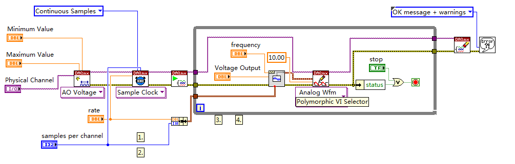
2. I enclose my VI (also shown below) for the output voltage. I put my writing of DAQmx Subvi in the while loop so that I can change the voltage while the VI is running.
However, in the example, the author has been reading outside of the loop and before even the start task. What difference will it make?
3. I have also attached my synchronized VI. I always put the wavegeneration and the DAQmxwrite in the loop. A bulging guard error saying about samples is not available and needs to a higher sampling rate or a longer wait time. What causes this?
I appreciate that these problems can be solved. Thanks to you all.
(1) first you need start the task of acquiring, he'll wait for trigger here. And then you start the build task that provides this trigger. If acquisition could trigger and never start.
(3) you must first write something in the buffer (writing DAQmx), then only you can generate it (Daqmx Start).
Check Cont Gen tension Wfm - Int Clk - no Regeneration.vi in the help-> examples for example.
-
Switch between outputs, digital and analog input
Forgive me, I'm sure that there is a simple answer to my problem, but being relatively new to LabView, I do not know how to proceed.
With the help of producer/consumer achitecture I am trying to accomplish the following:
Producer
- Relay nearby
- Read the voltage
Consumer
- Compare the voltage to the expected value and append the true/false value in a table.
It will be run 8 times then wait for input from the user through the dialog box run then 8 times.
My question/problem is how I set up so that the digital analog in and out are timed correctly and get a sample of AI after each relay is closed?
Material used is the cDAQ, (2) NI9481 & NI9221 (1)
Attached, is the vi that I came with this day and a diagram to illustrate the intended application.
Any help is greatly appreciated.
-
How to write constantly to analog output and read from analog inputs
Hi all -
I had a question about writing continuously to analog output reading simultaneously an analog input.
It's my first time to post a message to the community, so please let me know if I made mistakes.
I use Labview 2011 with a NEITHER-DAQ USB 6215.
I'm looking to generate a waveform and write it continuously in an analog output. It is then connected to an entry on the acquisition of data, where I am trying to sample the analog signal. (I realize, there is a system of trivial, but I'm hoping to build on it once I have run).
The task of reading from the analog input works fine, as I tested it in several other cases. I have a problem writing to the analog output.
For this task, I tried to follow the "Gen Cont Wfm Clck Int' VI to generate the wave form and start the task. I then try to write to the output of the analog timed loop. However, it does not seem to transmit a signal and doesn't give me any errors.
I have attached the VI but also a screenshot.
Please let me know if anyone has any ideas. I would really appreciate the help!
Thank you
Peter Borgstrom
We will review your tasks one at a time. First of all, the task of generation/Analog output Waveform. Generate you a waveform (I'm unsure of your VI if it is a fixed waveform or not) and send it to a defined output function to produce a waveform continuously, using N-channel and samples of N (where you set not these previously). You should not put this inside has timed loop, as the DAQ hardware has its own clock - if you simply put it in a while loop (with a stop to break out of the loop), the loop will call the function for the first points of N, wait until all N have been taken out, then call it again to another N points (up to what you press Stop).
Now, suppose that you have the output connected to a load voltage (say a decent resistance). You can wire the input terminals of your A/D converter through the same load and set up a similar analog input loop, running in parallel (i.e. in its own independent of the OD loop, while loop). You pourriez start together (with, say, a merged error since the initialization code line loops HAVE and AO become lines of error in "loops of sampling" described above), but you might want to delay loop (a little) the AI so that the OD has a chance to set the voltage before the bed.
I hope this helps.
BS
-
iMac with Thunderbolt - how to get the old analog inputs
I hang up my old Mac Pro in 2005. I used it to record video cameras and mainly music best of my plate rotating and stereo system - vinyl and CD disks via s-video and RCA cables and Firewire for Mac Pro.
The iMac 27 "new is primary Thunderbolt and I can't find a Thunderbolt conversion box so I can enter my analog input RCA and S-video signals. No indication on the Thunderbolt converters 'both ways' I can't exit analog in the iMAC, then the iMac as well?
They certainly run Final Cut Pro X on the iMAC, then how people get their old media and music in the machine?
I'm about to talk to the local Apple store, but the chances of finding someone who knows what they are talking about with the iMac, Thunderbolt and analog input is going to be a stretch.
Al Donn
You can probably use a converter DV firewire as a Canopus ADVC 110 http://www.bhphotovideo.com/bnh/controller/home?O= & sku = 349146 & gclid = CLSF0_qUnswC FQ8vaQod9VkFFw & is = REG & ap = y & m = Y & c3api = 187... and then an adapter firewire-crush.
-
You can synchronize digital input with an analog input on a 6034e?
Is there a way to synchronize the digital input and analog input on a 6043e?
I tried the test application "SyncAI_ReadDigChan", but it fails during the humor tick Verify():
"The requested value is not supported for this property value.
Property: NationalInstruments.DAQmx.Timing.SampleTimingType
You asked: NationalInstruments.DAQmx.SampleTimingType.SampleClock
"You can select: NationalInstruments.DAQmx.SampleTimingType.OnDemand.
I'm currently collecting analog input data for the duration of a digital input pulse.
Thanks for any help.
Joe
No, you can't.
The problem with E-Series cards, is that they have just static DIOs, so you cannot have their clock.
You would need a M-series card for that where you have correlated DIOs.
-
Need to read a 30, 1.5 a analog input using a NOR-9205
Problem: I need to read two analog inputs with good resolution using a C-Series card. The two beaches of signal are 0-30 V @ 1.5 and 0-5 V (not sure of the current). I need to be able to read the signal 5V with a precision of mV (or 16-bit resolution).
I looked at the module-9221, which works very well with the 30V, signal, but does not have enough resolution for the 5V signal. The 9221 is 12 bits on the beach of 60V.
I looked at the NOR-9205, which works very well with the 5V signal, but it cannot process the higher V 60 signal.
If a voltage divider circuit comes to mind, but has anyone found a good solution to this (other than to get both modules)?
Well, the current should not question. The entrance of the analog device (ideally) should draw no current and everything running on the source will cross the UUT.
A 4:1 voltage divider should evolve the signal to 9205 AI as long as you do not violate the absolute maximum voltage between a pin of the device and the Earth.
-
Analog input and output using 5640r
Hello world
I'm Christine, I'm implementing OFDM on fpga using 5640r.
The code that I have, which is good in the simulation using labview and also using 'nor 5640r treatment only' but I want to implement in "analog input and exit vi" so that I can send and receive on the same card 5640r
After so much attention in this regard, I am still unable to find the issue, then the soultion to this question. something that I am able to understand that maybe there would be some questions (ADC and DAC) clocks the clock setting
I have attatched that vi. Please take a look at
Concerning
Aqib
College of aeronautical engineering
Risalpur
Sorry
-
Several analog inputs seem to change any of the other (details DAQ: 2120 BNC and 6062E)
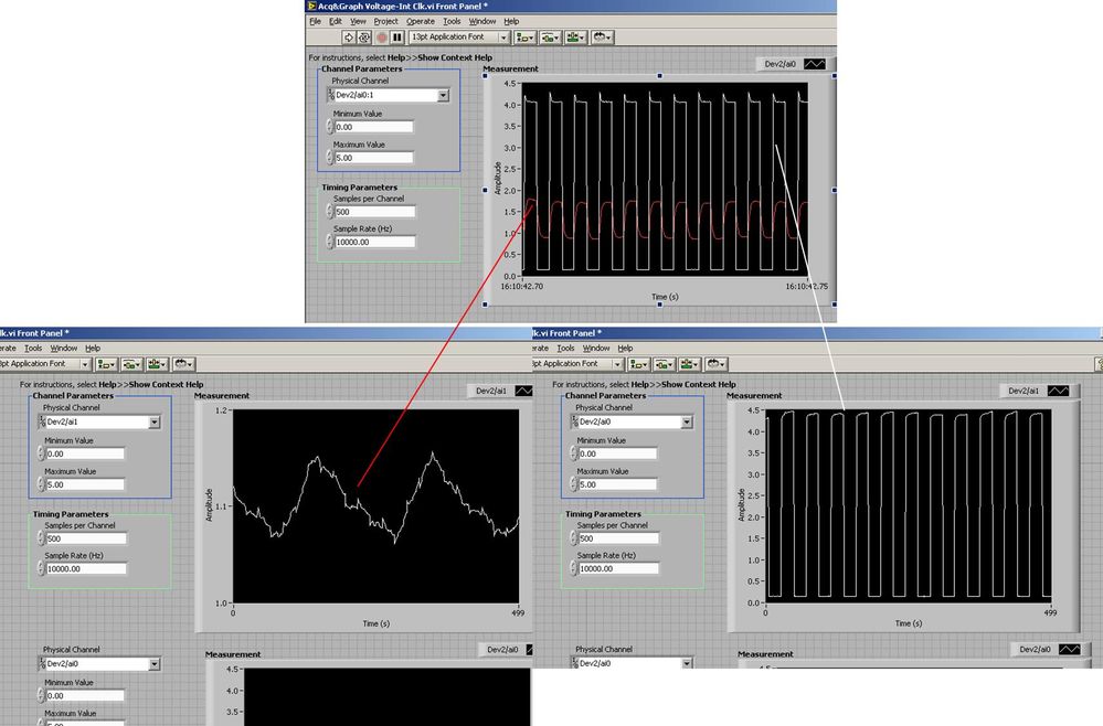
I use the BNC 2120 DAQ board connected to the data acquisition card 6062E to record two analog inputs. An entry is connected to ai0 and the other at ai1. Example vi: "Acq & graph int clk tension" has been used to measure the two entries with the value read NChan NSamp vi (channels being dev2 / ai0:1). The output is the top graph in the image. However, this seemed a bit strange to me that one of them should be modulating with a different frequency. When I record both entered individually (two in low pictures) they are indeed different since the entries shown in the top graph.

Why this would be the case, and how can I overcome this to measure the real signals?
Thank you!
The E series card takes the samples as soon as possible. Thus, for example,.
If you have 16 analog input channels but you only read of
channel 0 and 1, the map will show the channels 0 and 1 right
After and then wait 14 'ticks '. What's that little run-in
the origin of the afterglow.
I think you can get the card to wait a certain
number of ticks with a property node. I have attached a screenshot. You
can find the property node in the palette of functions >
Measurement of e/s > NOR-DAQmx > node Timing. Expand it
Property node so there's two entrances. The properties are in
Left click on the node and going more > converted >
Its properties delay units and sampling clock delay and delay that
you want.If the phase is important so the above is not the best
the option because it causes a delay in phase. So, if you need true simultaneous
sampling, then you will need different hardware. The S series is everything
simultaneous sampling.Or, rather than the Delay property and delay units, try the Rate property
find more > converted > rate.If this is not
work either, you can move the second signal source to, say, AI8 and
Connect everyone to the ground. Readings for these, but just do not take into account
the data. In this way the ADC will sag to the ground at the time where that can happen
the second string in the way so that you should not see this frequency
ghosting on the other channel.
Maybe you are looking for
-
Equium L20-198: Motorola ROKR as modem GPRS for laptop?
Hi, can someone help me.I have paired my Motorola ROKR E1 with my Equium L20-198 with a Bluetooth dongle and now I would like to use the GPRS service for internet connection.I can do this, or what I need to use a modem connection? Also how can I prev
-
HP G4-1303AU: lack of drivers - no Internet connection
I have the notebook above but I can't connect to the Internet. In Device Manager, it shows the yellow triangles with a '! ' for: -ethernet controller -network controller -PCI device -SM Bus controller Where can I find the drivers for them? I tried se
-
Please go go www.osocabins.com it comes to my site and several people with me are unable to enter, anyone know why?
-
selection of the right Startup Repair boots me back to the screen to select reboot
recently installed new graphics - no problem. has had to unplug my dvd player because the sata power cable is not reached. I bought a 4 pin sata converter plug in. Since then, I could not get into windows. But first, the computer would send signals t
-
failure to communicate with the image drum?
My m175nw is only 2 weeks... Everything worked great until I did the Firmware update. Now, I get the following error and I think I printed only one (1) page since I bought this thing 10.0004 power error10.1004 supply memory error There is a failure