oscilloscope...
Hello
I use the generate an example of digital pulses finished vi to the ttl to generate from my card NI PCI-6601 impulses. I want to see the pulse output on an oscilloscope, how can I do this?
How can I connect a graphical indicator to show the pulse?
I have attached the vi that I use:
Missed the fact that it was only one meter.
You can always use a scope to connect to the output of the counter.
Tags: NI Software
Similar Questions
-
How to create a continuous Oscilloscope XY?
Hello
I create a continuous Oscilloscope XY on 2013 LabWindows/CVI.
I did find a solution with the Stripchart library because I want to implement the axis X-Y year, then I tried with a graphic.
The solution works, but I must now deal with important treatment when my points buffer is full and I do memory operations on this!
For indication I view the 10,000 values by curve and I have over 50 curves.
Anyone know a solution to implement a continuous oscilloscope XY?
And is there a way to optimize my time processing problem?
Thank you for your help.
Charles
-
half-wave rectified filter circuit/oscilloscope measurement
Hello everyone, I hope I can get help on this fundamental issue, I'll have. University online, with which I will not help me, so I hope that I can quickly get assistance here.
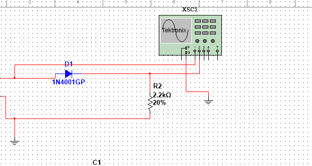
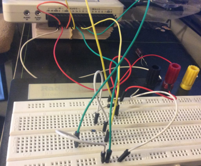
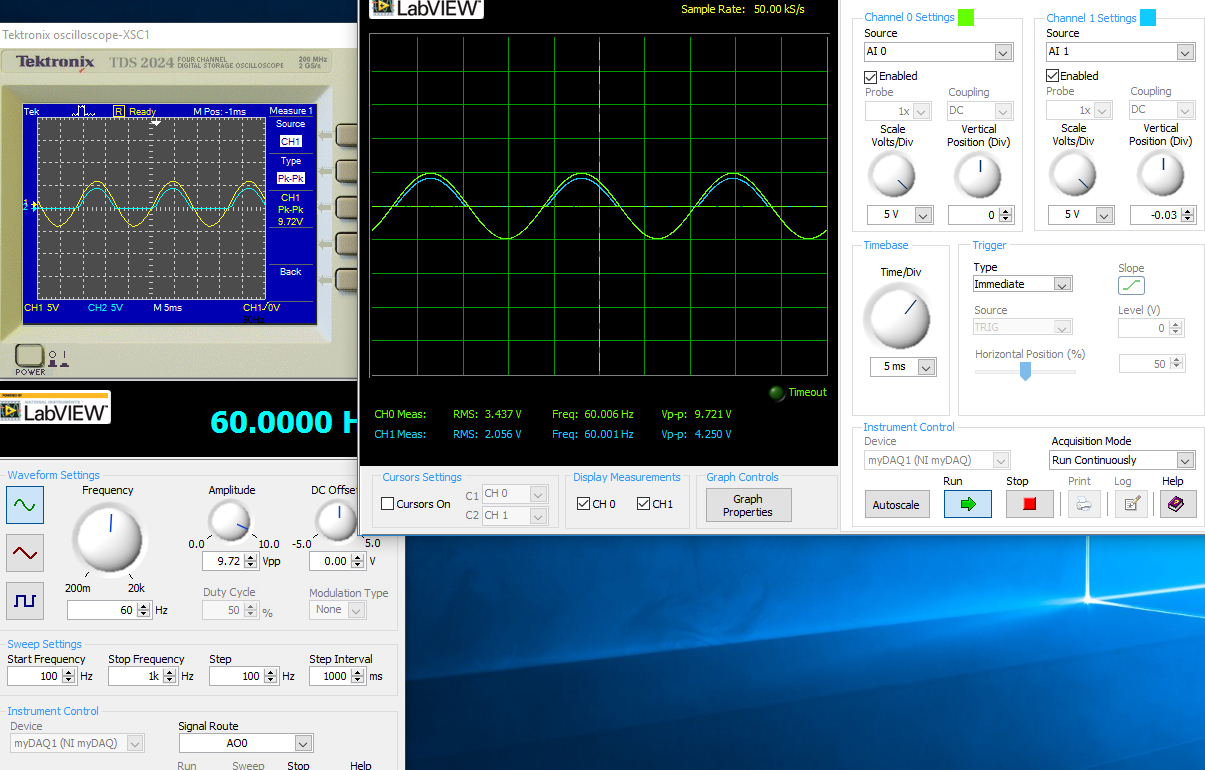
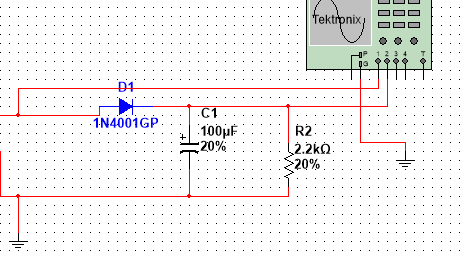
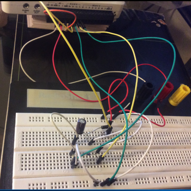
I have the myDAQ NOR, I have to build half rectified filter circuit with a resistance 2.2kOhm, I also use the multi-sim to confirm the measures of waveform. Everything goes well on Labview multisims Tektronix Oscilloscope compared to before I connect a capacitor 100uF my comparison heres:
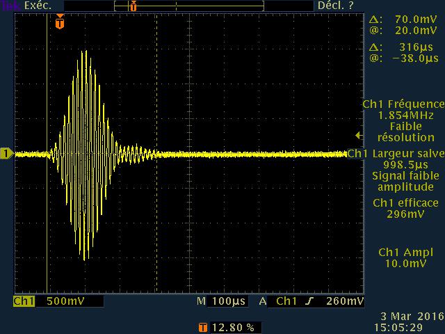
The model is just the Diode with a series resistance 2.2kOhm, I'm not sure if the analog inputs to the LabView Oscilloscope are configured correctly this is the air I get:
This satifies my simple comparison on the Multisim circuit, since I came here for a few hours to play with probes analog input, I know that something is wrong out of these measures, I get.
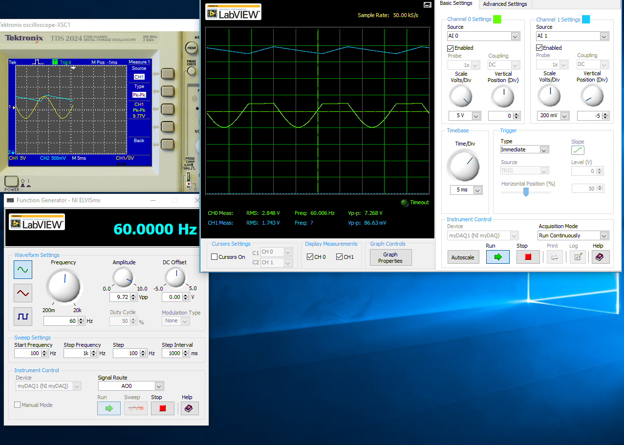
With a capacitor 100uF in parallel:
I think the question is how I inputs analog and STILL plugged, I'm not sure that this is where I would really like some help or any type of assistance. Once I get this set up right, I'll be able to take measures for the frequency, load DC, P - P Ripple voltage ripple and then move to a full-wave rectified circuit. I just started a course and received the myDAQ.
Henrik_Volkers wrote:
Compare it with the current specification of output of your myDAQ

Here is a link to the specification: http://www.ni.com/pdf/manuals/373061f.pdf
Henrik hit it on the head. The myDAQ can, at most, out 2mA with analog output. So, with a 2.2kOhm charge, which puts you in 4.4V without the diode. The led will also require an amount of current. According to my estimates, subject of 1mA (your pic is ~2.5V, divide by the 2.2kOhm to get ~ 1mA). You will see only that on the positive side of the sine wave as the diode blocks all the negative side.
The lesson here is to make sure that your outputs have enough power to do what you want. You can go to get a simple op-amp from digikey and use a follower of tension for editing the current upward. You will probably need another power supply or two (+ 12V and - 12V) to power op-amp.
-
virtual oscilloscope + trigger?
Hi, I have a problem, I do virtual oscilloscope with NI USB-6008 card, one has everythin but I had one problem, I can't do trriger to my oscilloscope, I wish I had a pick on the rise or down trigger, I take my cue to the generator. Can someone help me?
...
Useful starting point:
LabVIEW or CVI > help > find examples... and look for "triggering".
Continuous analog acquisition with digital startup is what you are looking for, are you not?
Best,
Matyas
-
Persistence digitizer/oscilloscope waveform
Normal
021
fake
fake
fakePT - BR
X NONE
X NONEMicrosoftInternetExplorer4
/ * Style definitions * /.
table. MsoNormalTable
{mso-style-name: "Table normal";}
MSO-knew-rowband-size: 0;
MSO-knew-colband-size: 0;
MSO-style - noshow:yes;
MSO-style-priority: 99;
MSO-style - qformat:yes;
"mso-style-parent:" ";" "
MSO-padding-alt: 0 cm 0 cm 5.4pt 5.4pt;
MSO-para-margin-top: 0 cm;
MSO-para-margin-right: 0 cm;
MSO-para-margin-bottom: 10.0pt;
MSO-para-margin-left: 0 cm;
line-height: 115%;
MSO-pagination: widow-orphan;
font-size: 11.0pt;
font family: 'Calibri', 'sans-serif ';
MSO-ascii-font-family: Calibri;
MSO-ascii-theme-make: minor-latin;
MSO-hansi-font-family: Calibri;
MSO-hansi-theme-make: minor-latin;
mso-fareast-language: EN-US ;}Is it possible to have the scanners NOR
show waveforms with persistence as benchtop Agilent and Tektronix
Oscilloscopes? I understand ZTec modular oscilloscopes have this function. I have
guess, it can be progemmed using LabVIEW, but is there one out of the way of the plateau of
do?Thank you.
It is currently not a single property or a function that implements persistence for NOR-SCOPE. Your interest for this feature was placed along R & D for future consideration.
You're right that you can set this feature in LabVIEW. I consider using a graph of intensity. The value of x is your time, the value of is the extent of your blood and you browse your waveform, you must create the z values to show the persistence of the wave. Maj reqisters can be used to track the intensity of the previous iteration.
-Jennifer O.
Product Support Engineer - scanners-high speed
-
MAX does not allow me to rename the tektronix oscilloscope
Hi, I'm trying to set up my TDS 2014 C Tektronix oscilloscope, but I have a few questions:
(1) I can't rename the Max machine (I have installed TekVisa). Here is what I get (see the file attached jpg). So, what happens here?
(2) my scope is connected via USB and MAX sees, but all examples are for serial communication and I see no VI to the USB, but when you download the instrument driver, it said USB-compatible. What should I do to get the examples running for USB?
Thanks in advance...
First of all, there is no reason Tek-visa application must be installed. You just need to NI-VISA, especially if you plan on using LabVIEW, secondly, how weak is slow? Seconds, minutes? What command do you send to MAX? Third, your scope is a USBTMC device and is listed as such. There is no specific to USB example since one is not necessary. The same code works for the GPIB, series, or USB. Ignore you the control of parameters series.
-
Error time-out random - 1073807339 using pilots of series Oscilloscope Tektronix TDS 200 1000 2000
I am trying to make measurements of waveform of an oscilloscope Tektronix 1052 B using LabVIEW. My program is intended to be run for hours at a time, and it works perfectly as expected for the first few hours. However, I noticed that after a few hours, there are apparently random of chances that a VISA to read or write the block function will produce the error - 1073807339. After that happens once, all read or write functions also produce this same error for a while. This happens even using subVIs new driver provided by OR (http://sine.ni.com/apps/utf8/niid_web_display.download_page?p_id_guid=047216EC20B66FABE0440003BA7CCD... Meanwhile if I stop the program, I can still bring up the oscilloscope in MAX and read and write commands him. The error seems to occur within a VI. I already read this page here: http://digital.ni.com/public.nsf/allkb/874B379E24C0A0D686256FCF007A6EA0?OpenDocument, but none of the solutions helped. I know that this is not a matter of actual timeout because I tried increasing the timeout of 30 seconds, but the error always occurs immediately as soon as the function of reading or writing block is called.
I would like to know why this is happening and what can be done to remedy this. The Subvi in question is provided. This VI is called at various points in the program do acquire a waveform. The inititialize and narrow subVIs are called outside the Subvi.
Then check your powersettings. Windows may unexpectedly turn off usb power
-
PIN IEEE488 Oscilloscope Gould 1602
Hello
I have an old digital oscilloscope of Gould 1602. At the rear, there are socket IEEE488 and RS423 taken as well. I would use the IEEE488 one.
My only problem is that I have never seen such decision-making GPIB far and I do not know the PIN. It has 48 pins and I don't know what to do.
I've attached a picture to this topic.
I have aklready tried to find any souliton on the internet but I could not.
I want to tell you thanks for any help.
Looking at this photo, my guess is that the man who bought this scope originally it did not buy with either IEEE488 or the RS423. Other hardware parts plugs on the two white connectors when these options were purchased.
-
acquire data from the oscilloscope DPO2024
I am trying to acquire data from the oscilloscope DPO2024 using labview. I am able to do, but my vi file only works for channel 1. Other than channel 1, it does not work and instead, it changes the adjustment of the oscilloscope as well. Find the vi files attached.
Any help is very appreciated.
You must connect the channel in the waveform of reading. It is default to channel 1 if thread continues.
-
Help with oscilloscope Agilent 54810 A data recording
I use an Agilent 54810 A oscilloscope with GPIB interface, I can't save the voltage (y-axis) and data(x axis) of the time together. I can only record time data.
could you please help, I would like to save the data to a text file.
I don't know why you say that you are only able to save the time data. What you save is the data. If you want to use scripture to measure file, create a waveform based on data type of Y and x increment that you receive from the wave function of reading. You simply use the wave function build for it (inside the loop).
With a constant True not wired to the GOLD from inside everything in fact point of termination of the loop makes no sense. Might as well not have while loop. With a single iteration, I understand not also the purpose of the exit of the auto-index in a 2D array.
-
Hello
I used Tetronix TDS210 oscilloscope to the data of the Squire. But I need to change the oscilloscope LeCroy Wavejet 324 now. The program is not even read the signal now. What are the things I need to change?
Thank you
Quite frankly, I suggest a complete rewrite. You use stacked sequence structures, GPIB functions instead of VISA, a large number of locals, the hidden wires and structures, in a first stage. You should know that the command set varies from one provider to another and often from instrument to instrument. If you had used the instrument to the extent of tek driver, you could perhaps have an easier time to replace common functions. As it is, if you want to use the existing code, you need to replace each of your Scriptures GPIB hardcoded with writing appropriate for the LeCroy.
As a side note, this is the kind of situation where IVI drivers would have made a big difference. If the IVI drivers exist for the two instruments, and if you used class drivers, you would have not had to change anything.
-
Hey Hey everyone
I was looking for an example for two-channel oscilloscope virtual using e/s all-in-one of the 14 bits of NI DAQ USB 6009. I tried to research for example BOF time division or s/div for 1 second, 5 seconds, 10 seconds. but was shocked to find that there is no reference for it. The range of oscilloscoper virtual
Minimum - 10 micro s / div maximum -10milli second div but there is no example for 1 second / div or 5 seconds / div... If anyone can guide me. I'm new to labview environment.
This is the oscilloscope two sample obtained from google search. is there material limitations. ?
I'm working on continuous 4-channel data acquisition data acquisition using niusb 6009
The sampling frequency is sufficient for any desired s/div. The sample rate is 12 ksamples / s per channel, so if that meets the Nyquist criteria for the input signal, you can capture it. The number of samples has no effect on that with the exception of the amount of the signal you acquire. Your chart is not stable, if you do not trigger the acquisition. Even as real significance, therefore your emulation seems actually successful.
-
Hello
I'm doing the acquisition and processing of an oscilloscope, signal
and I would like to know if I could have the photo goes on the oscilloscope on labview
"without going through the graph of the function" the exact image on my oscillocope: see local closed.
-
How to subtract one signal on the other, with the help of an oscilloscope?
I have two chaotic oscillators, which I am trying to sync. There is an oscilloscope, which channels are related to each oscillator. I need remove the signal from the oscillator-B, the oscillator signal - A, using the oscilloscope, so that I can find how much is the error between them. A - B would work very well, but there is only A + b. is it possible to do, without having to add additional circuit elements? If this isn't the case, that I would add, subtract one signal from another?
Edit: I use the classic Multisim 13.0 oscilloscope.
Hello.
You can invert the signal B-
the standard scope 2 ch a reversal for Channel B - there are 4 small buttons on the bottom of the chB instead of only 3 for chA.
Best regards
Michael
-
Oscilloscope (tds420a vi) missing
Hi all
I use tektronix oscilloscope tds420A. And I also to download drivers for this oscilloscope but when I try to open it in instrument drivers showing a few missing vi. I have attached screenshot of this.please help me to find the solution to this problem.
Thank you
Do not attach the owners file formats. It seems that there is a problem with the mnu pointing functions in tktdsxxx.llb file. Remedy must go to tools > advanced > change a Palette set. You can search for the pallets with the missing items and make an insertion > screw select the screws in the llb and then delete the icons with the question mark.
Maybe you are looking for
-
Portege 7200 multiple problems
Hello It is my last ditch attempt to try and get some sort of difficulty for my Portege 7200. I will try to explain as best as I can, so this is. I had a system dual boot (Linux & Win98), did not want Linux HD so formatted and reinstalled Win98. Ever
-
map of webOS 3.0.4 battery problem
Management of cards and stacks of map has changed/broken with the update. It seems that you are no longer able to re - order of batteries, desempilement or cards from the stack. The ability to manage the batteries of the card was a great more for the
-
How can I send several pictures by e-mail in bulk at the time?
I try to send a file of 100 + photos and not having to add to email one at a time, which has been taking me about 30 seconds per photo. tried to drag the folder in the email and that did not work. Please if I can do it could you please send me an em
-
I'm trying to install Microsoft Sidewinder Precision Pro on a Vista platform
MS sidewinder controller sw 3.0 Windows Vista Home edition
-
Compile the LabVIEW code in DLL?
Is it possible to create a DLL using only LabVIEW? Such that the DLL can be installed on a non-labview system and used by other languages such as C? -L'application would be low-level for use by other platforms as LabVIEW for the development of hardwa