virtual oscilloscope + trigger?
Hi, I have a problem, I do virtual oscilloscope with NI USB-6008 card, one has everythin but I had one problem, I can't do trriger to my oscilloscope, I wish I had a pick on the rise or down trigger, I take my cue to the generator. Can someone help me?
...
Useful starting point:
LabVIEW or CVI > help > find examples... and look for "triggering".
Continuous analog acquisition with digital startup is what you are looking for, are you not?
Best,
Matyas
Tags: NI Products
Similar Questions
-
Generate data with 6722 and reading back with 6221 - it visualization with a virtual oscilloscope
Hello
I generate an analog signal with the 6722 and want to read with the 6221. The results shall be included in the virtual oscilloscope. My problem is that I don't know where to put the signal-chart and that I really need to use type. The second problem is that I have no idea how do I choose a time scale and where and how to define. Finally, I have that image that I get on the real oscilloscope with data generated by 6722 on the virtual oscilloscope with the 6221. Initially, the oscilloscope should have no (mode of operation only) trigger as the 6221 has only a digital triggering.
For the moment, I have a loop that generates the signal using a sequence. Now, the question is where to put the signal-chart and what settings should I use for reading back information (1 sample, continuous, etc.).
Thank you
Verena
Hi db2nc,
Here is a link for an example of our community. It shows you an example with which you can generate a signal on output and gain on a different entry.
I think that's what you want to archieve.
Loopback synchronized analog output of analog input
concerning
Michael
-
Virtual oscilloscope; Slow Data Acquisition (limit of 5 Hz)
Hello.. I tried for a some time now schedule a virtual oscilloscope using the software or Labview and materials acquisition of data USB-6009.
This has been my best attempt to date: http://www.andthenbam.com/FievelScope.vi
I seem to only be able to measure frequencies up to 5 Hz, then the frequencies of signals begin to repeat themselves. I am aware that this device is capable of a MUCH faster speed. I'd appreciate it if someone could take a look at my VI and recommend a solution.
Acquisition mode: 1 sample (on request)
Buffer: 100 samples
I failed to raise other modes of acquisition work. Help, please!
Here I explain my problem:
http://www.YouTube.com/watch?v=k8oI9mL8ZD4
Ty
Your problem is that you are setup to do one sample on request. This means that you count on the loop to set your frequency of acquisition. You probably really want to continuous samples with a rate that is much higher, depending on what you are trying to capture.
Looks like you're trying to sample every 100ms. It is 10 Hz. Therefore Nyquist function, 5 Hz is the highest frequency that you can enjoy. Anything more than that will alias down in the 0-5 Hz range.
-
Virtual oscilloscope; Setting frequency of data acquisition
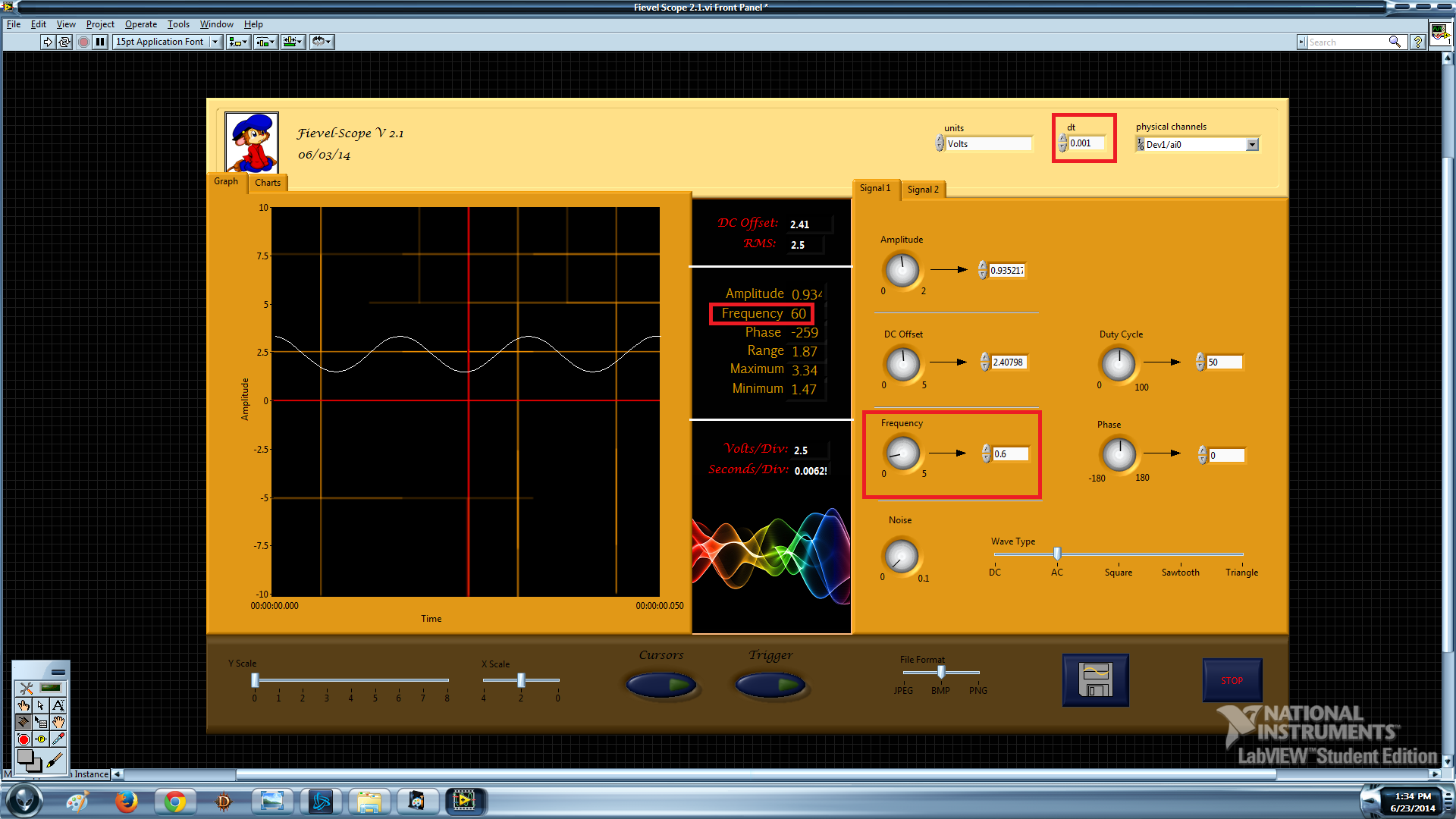
Hello world! I tried to program an oscilloscope using the Labview software and acquisition of data USB-6009. It will be very soon, but I can't seem to set the rate of acquisition of data at the correct speed. Let me show you what I mean:
waveform dt: 0.1
Frequency: precise
Limit: 5 Hz
Explanation: "[0.1 dt] is 10 Hz. Therefore Nyquist function, 5 Hz is the highest frequency that you can enjoy. Anything more than that will alias down in the 0-5 Hz range. "- Crossrulz
waveform dt: 0.001
Frequency: x 100
Limit: 500 Hz
Explanation:? The frequency seems to be dividing by dt at some point.
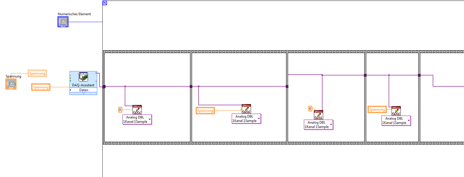
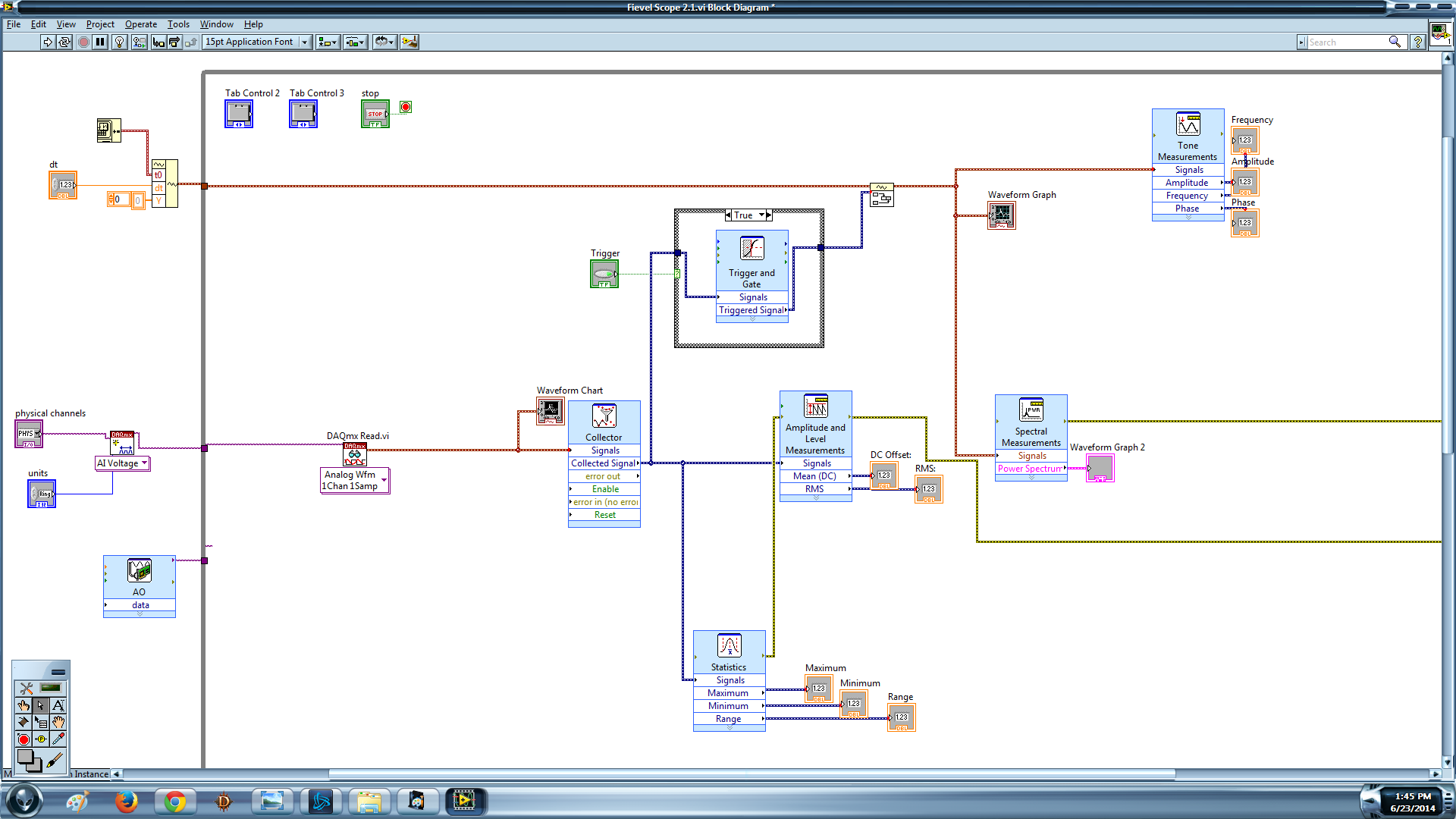
I like for this oscilloscope simultaneously read faster than 5 Hz and be precise. Here's my block diagram if someone would be willing to take a look:
Create the channel-> read-> buffer / collector-> Trigger-> Append--> measures/graphic
A last word: the dt that I am changing is on an empty wave form which I enclose with my signal to input in the upper left corner.
You run the examples that come with LabVIEW? STOP using the 1 sample DAQmx Read. Right-click on it, and change the type. The other mistake would come if you have changed the similar to the task. Delete this part because you don't use it.
-
Virtual devices trigger a prompt to activate windows.
Whenever I have activate a virtual virtual device as virtual wifi, HDD or DVD virtual Windows asking me to activate windows in 3 days... How can I stop this. my new month keys only one couple asked me to register with windows already 4 times. And only the material that changed are peripheral virtual without real physical hardware. already a key had invalidated by this phenomenon and had to buy a new one.
I use windows 7 64-bit ultimate. my previous windows was windows 7 64 bit home edition. upgrades hardware only it was a hd internal tv tuner and more ram...anyway to stop this before I have to buy another key?Thank you in advance,JeffHi Jeff,
I appreciate the efforts that you put to publish the query on this forum.
I suggest that you post the application on Microsoft TechNet forum because we have experts working on these issues. You can check the link to post the same query on TechNet:
http://social.technet.Microsoft.com/forums/en-us/home?Forum=w7itprovirt
Please do not hesitate to contact us if you have other questions related to Windows.
-
How to trigger the camera and light pulsed with PCIe-1427
Hello
We recently bought an acquisition card NI PCIe-1024 and the NI Vision Builder.
I am new to imaging applications and need support to get started.
Application:
We have a camera viewing a scene which is illuminated by a pulsed light source (e.g., a strobe).
We want to use the PCIe-1427 as the master for the outbreak of the camera and strobe light.
The first trigger (Ch 0) transmitting signals TTL to camera to 30 Hz (30 fps).
The second trigger (Ch 1) send bursts of pulses to the strobe light to e.g. 10 kHz. This trigger must only send impulses all other images, so that we can save alternating light and dark images in order to perform background subtraction.
I tried to set up the channels of the trigger and create virtual channels in the measurement and Applications Explorer, but apparently this is not possible.
Since it is an application critical time, I'd appreciate an example vi that sets up the channels two trigger and download managers in the camera to get started on this application. Thank you.
Software of NEITHER: LabVIEW version 10
Materials: Device for the Acquisition of Image (IMAQ) PCIe-1427 driver Version: NOR-IMAQ 4.4 OS: Windows 7
Thank you, Justin.
I'll copy this request to the machine Vision Group as you suggested. I looked at the link sent you me and made progress (limited). I can see on an oscilloscope trigger signals, and the camera acquires images. However, I only managed to do work for pulse trains continuous, not a shots or bursts of pulses.
No need to answer that. Thanks for your help.
Peter
-
Alarm for the latency of disk esxi-home
I would like to set a new alarm to monitor all esx host disk latency in our vCenter.
We found the settings, to set up this point for a virtual machine.
[vCenter alarm-> add new detector for a virtual machine-> trigger Type: disc Total VM Max (ms) latency]
So we need the same alarm, but for the esx host. But I can't find the right trigger type neighter events on the right (for which we can configure an alarm).
The problem is that sometimes the Raid Controller battery is defective and then we notice everything by checking the performance of the disks-esx table:

We need an alarm for exactly this measure: drive higher (ms) latency.
I also searched for setting up an alarm in the store of data according to, but without success.
Maybe someone has an idea how to set up such an alarm.
Hello!
There isn't any support in Client vSphere or vCenter. You can use esxtop to know but there is a lot of work to get a sort of wake-up call.
A VMware product for this is vCenter operations, but it might be too depending on your environment.
There is many products from 3rd party who will do that for you. vKernel VoP (formerly called vFoglight and I think that Veeam One will do this for you.)
-Martin
-
Strange in form of images as links
For simplicity, let's say I'm trying to recreate the American plan from here: https://www.politicalpagesdirectory.com/states
I have a bunch of photos with an alpha channel that would make a 'map '. They would be next to each other and each of them would be a clickable link. This means, that some of the alpha channel of a photo ecaple visible chart of another. I want a user can click on any part of the image and not the invisible (alpha channel) but. Is it possible in muse weird shaped links photo like that?
The short answer is no, not to my knowledge. As you can tell, you can use PNGs with transparencies, but problems of cliquabilite where transparency overlaps another area.
Now this Muse supports SVG, you could try to import SVG assets that are the exact form of the 'State' of any desired illustration; rather than to the place with transparency. However, I am very skeptical as to how this works.
I suggest the following:
-Adobe edge animate. Muse supports direct import of the oam of the canvas and this task is easier to lively edge and if you're not already familiar with it, defo need to spend a little time to get used to it - really worth. In short, to place items on the timeline, click action and use tags onhover and onclick with your code 'action '. Interesting to look at the Commons of edges to simplify your task. See the thread: Re: work with mouseover/no active definition and forms of polygon areas (imported forms)?
-If you insist to do that in Muse, don't forget you can make virtually any trigger transparent polygon by stacking square-shaped transparent of different sizes and orientations and then grouping them and then giving it associates hyper link. Bit painstacking works, but it will work.
-If you're feeling brave / want really stuck in: svg - how area be irregular in shape not rectangle? - stack overflow
Hope this helps
-
Trigger oscilloscope return value
Hello
I'm under Labview 8.2.1 to control the Wavesurfer oscilloscope optionx/IP 64xs. The drivers are downloaded from OR http://sine.ni.com/apps/utf8/niid_web_display.model_page?p_model_id=14665.
The oscilloscope acquires burst signals, and I need to use average (~ 10) to reduce the noise. The signals are controlled to change immediately after the previous data is read and stored. But the 'Reading Signle Waveform.vi' program can only wait for 1 mono RELAX and stop, that I found is because the subroutine "Initiate.vi" will write the code of the buffer ' * CLS; ARM; "to the oscilloscope. So I'm not able to do an average on the oscilloscope now.
I wonder how can I put it to auto trigger aftering reading of the form of wave, or alternative methods to achieve an average.
Thank you very much...
Hi Qlong,
Alan and LeCroy Support here... The pilot has a function for this: "configure the Acquisition continues." This VI allows to configure the SHUTDOWN, AUTO and NORM triggering modes. Use Insider for the single release.
Best regards
Alan
-
Hey Hey everyone
I was looking for an example for two-channel oscilloscope virtual using e/s all-in-one of the 14 bits of NI DAQ USB 6009. I tried to research for example BOF time division or s/div for 1 second, 5 seconds, 10 seconds. but was shocked to find that there is no reference for it. The range of oscilloscoper virtual
Minimum - 10 micro s / div maximum -10milli second div but there is no example for 1 second / div or 5 seconds / div... If anyone can guide me. I'm new to labview environment.
This is the oscilloscope two sample obtained from google search. is there material limitations. ?
I'm working on continuous 4-channel data acquisition data acquisition using niusb 6009
The sampling frequency is sufficient for any desired s/div. The sample rate is 12 ksamples / s per channel, so if that meets the Nyquist criteria for the input signal, you can capture it. The number of samples has no effect on that with the exception of the amount of the signal you acquire. Your chart is not stable, if you do not trigger the acquisition. Even as real significance, therefore your emulation seems actually successful.
-
5154 PXI trigger on the external input
I use a PXI-5154 and want to change my previous program to trigger the external source. I'm feeding the external source from source to V 2.5 and it seems to trigger fine. However when data acquisition the vertical range of the oscilloscope will 5 V which is too high as to my request I acquire in the millivolts range. I tried to show the vertical range of the channel I acquisition, but although I put it as the active channel I get the following error:
Error 1074118616 has occurred to the property node (arg 1) in PD_measurements_v11_test.vi
Get a base attribute value channel failed because the channels interviewed have different values. Please specify a channel when you query a string based attribute.
I enclose you a printsceen of the relevant part of the code.
Kind regards
Karavellas
Dear Tunde
I managed to make the changes you suggested and the works of the example. I'll look in my code and see what the problem is. I'll get back to you if it has been fixed in my code or not.
-
Problem of generation of Sync trigger in several synchronization USRP RIO 2943R problem
Generation problem shutter Sync in several synchronization USRP RIO 2943R problem.
Previous SR you may already know I'm stacked in USRP RIO multiple synchronization problem, especially in the mode based on the signal. Now I can cut down, the problem is mainly due to the outbreak of sync signals generation.
First of all, I read the article and the discussion in the following two links:
http://forums.NI.com/T5/USRP-software-radio/how-to-synchronize-multiple-USRP-Rio-294x-devices/TD-p/3...
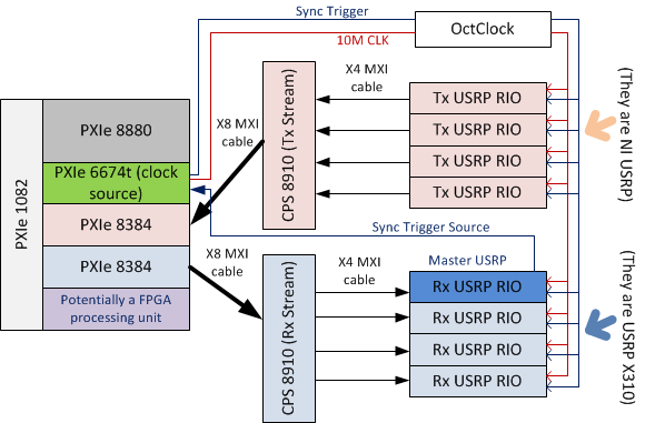
http://zone.NI.com/reference/en-XX/help/373380D-01/usrphelp/synchronization/and I did my connection of the material according to the suggestions in the second link. My system schematic is shown in the following image:
I checked OctColck and SMU 6674 T connections. They are all connected correctly and the cable are fine. I use the niUsrpRio200_XcvrSyncPps.lvbitx.
According to the description of documents and discussion forum, the USRP RIO 1st in the list of devices are considered to be the USRP Master. Then, the FPGA to master USRP RIO released "trigger of sync" signal through the 'PPS Trigger Out' SMA port in RIO USRP box.
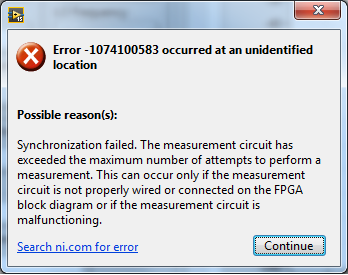
Based on the my analysis of the system, the first impression I have is the USRP Master does not export the 'sync trigger' correctly. The host VI reports the error like this:I was trying to measure the "synchronization trigger" using oscilloscope, but I found that it is impossible, because the host VI can not yet run, so there is that no signal can be seen from port 'PPS Trigger OUT.
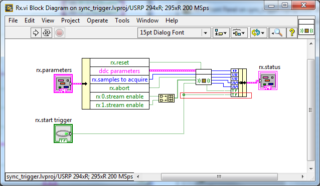
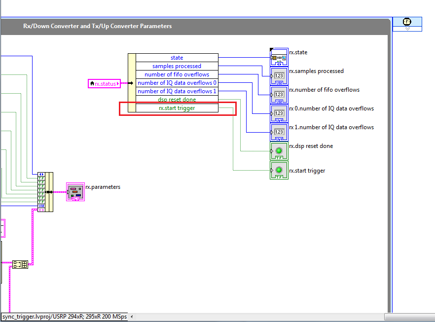
So I think that if I can watch this signal "sync trigger" in home VI by importing this signal from FPGA to host VI. I did some changes on the FPGA VI as shown in the following image to watch this signal of façade of the host VI. but not so successful. the rx.start tragger relaxation and tx.start do not appear on the host vi read/write control function.
-
How to read from the beginning to reference trigger?
Hello!
I develop a system a little on a NI DAQmx 6025 and want to know how can I get data from an early relaxation of reference.
I use "AcqVoltageSamples_IntClkDigStartAndRef.2008" to control the unit in c#
If I set up the Starttrigger only, I can trigger... (the measure is to start by climbing aboard PFI0)
---------------------------------------------------------------------------------------------------------------------------------------------------------------------------------------------------------------------------
myTask.AIChannels.CreateVoltageChannel (physicalChannelComboBox.Text,"", (AITerminalConfiguration)(-1), rangeMin, rangeMax, AIVoltageUnits.Volts ");
myTask.Timing.ConfigureSampleClock ("", sampleRate, SampleClockActiveEdge.Rising, SampleQuantityMode.FiniteSamples, 1000);
myTask.Triggers.StartTrigger.ConfigureDigitalEdgeTrigger ("/ PFI0/Dev1", DigitalEdgeStartTriggerEdge.Rising);
Reader = new AnalogMultiChannelReader (myTask.Stream);
...
drive. SynchronizeCallbacks = true;
drive. BeginReadWaveform (-1, New AsyncCallback (myCallback), null);
... MyCallback...
data = reader. EndReadWaveform (ar);
---------------------------------------------------------------------------------------------------------------------------------------------------------------------------------------------------------------------------
Now, I want to stop my measurement by the trigger of the reference, so I set up the Referencetrigger on the same source (PFI0)
myTask.Triggers.ReferenceTrigger.ConfigureDigitalEdgeTrigger ("/ PFI0/Dev1", DigitalEdgeReferenceTriggerEdge.Falling, 10);
(This line is after the configuration StartTrigger)
If I start the task and give the triggersignal, the measurement starts. But now the measure must stop if I start PFI0 again!
I don't know what I have to do to become a measure from the beginning to trigger Stop... I mean PFI0 PFI0 rising Edge edge
Thanks for the support!
Suchen für alle die noch immer nach einer Antwort, ich habs jetz!
For all who are looking for this answer, I get it now!
--------------------------------------------------------------------------------------------------------------------------------------------------------------------------------------------------------------------------------------------------
myTask = new Task ("aiTask"); Create a new task
Initialize local Variables
Double sampleRate = Convert.ToDouble (rateNumeric.Value);
Double rangeMin = Convert.ToDouble (minimumValueNumeric.Value);
rangeMax double = Convert.ToDouble (maximumValueNumeric.Value);
Create a virtual channel
myTask.AIChannels.CreateVoltageChannel (physicalChannelComboBox.Text, "", (AITerminalConfiguration)(-1),
rangeMin, rangeMax, AIVoltageUnits.Volts);
Set up sync Specs
myTask.Timing.ConfigureSampleClock ("", sampleRate, SampleClockActiveEdge.Rising, SampleQuantityMode.FiniteSamples, 1000);
Configure start and reference triggers
myTask.Triggers.StartTrigger.ConfigureDigitalEdgeTrigger ("/ PFI0/Dev1", DigitalEdgeStartTriggerEdge.Rising);
myTask.Triggers.ReferenceTrigger.ConfigureDigitalEdgeTrigger ("/ PFI0/Dev1", DigitalEdgeReferenceTriggerEdge.Rising, 100);Check the task
myTask.Control (TaskAction.Verify);
Create the object reader
Reader = new AnalogMultiChannelReader (myTask.Stream);
Start the task, and set the playback position
myTask.Start ();
myTask.Stream.ReadRelativeTo = ReadRelativeTo.CurrentReadPosition;AnalogWaveform
[temp]; {while(!myTask.IsDone)}
Temp = reader. ReadWaveform (60000);
}myTask.Dispose ();
--------------------------------------------------------------------------------------------------------------------------------------------------------------------------------------------------------------------------------------------------
Mit dieser Lösung kann man von mension zu messen mension.
With this resolve you can measure from edge to edge.
-
Get the double trigger using CreatePulseChannelTime on a single machine
I use DAQmx in c# to monitor a TTL (wide 3ms) signal, wait a while and then send a pulse on the line of meter output (wide 1ms). I put it to be redeclenchables so that for each input pulse, I get an output pulse after the waiting period. It works like a charm on a single machine.
On the other hand, I get two pulse output. If I change the value of my delay, the two impulses are delayed by levels, and their interval is exactly the width of the input pulse. Looks on the scope of the trigger occurs on both fronts and, even if I asked only the Levant.
As a hack, I extends the duration of the pulse to 3ms output, so that he survived the trigger pulse. This solved the problem, but is not sustainable in the long term because it limits the rate, I can do this operation.
Everyone knows this behavior, or have clues? My understanding is that the task will not retrigger until he sees another front, and that the falling edge will not retrigger it.
Oh - we exchanged the PCI-6052E card by a new one, but the problem remains. This problem will NOT occur on a machine we built 6 months ago.
Here is the code:
_triggerTask.COChannels.CreatePulseChannelTime (_cameraCounterLine, string. Void, COPulseTimeUnits.Seconds, COPulseIdleState.Low, 0, _delaySecs, triggerLengthSec);
_triggerTask.triggers.StartTrigger.ConfigureDigitalEdgeTrigger (triggerLine,
DigitalEdgeStartTriggerEdge.Rising);
_triggerTask.triggers.StartTrigger.Retriggerable = true;
generate 1 pulse
_triggerTask.timing.ConfigureImplicit (SampleQuantityMode.FiniteSamples, 1); _triggerTask.Control (TaskAction.Verify);
_triggerTask.start ();
Thank you-
John Duddy
We just thought to it - the Heisenberg uncertainty principle applied to the classical mechanics. The problem disappeared when we disconnected the oscilloscope. Without the connected frame, we had to deduce the problem disappeared (not), but I am convinced. It was the same scope, we used the last time, too.
It's a good lesson - when occur contradictions, check your premises.
-
Different frequencies of signalexpress with oscilloscope
Hello
I'm new to the signal processing. I am facing some difficulties to measure the signal of a sensor of acoustic emission for my project. I use the PXI-6115 module with 1042 q and terminal block is TB2708. I used AI0 and AI1 for main signal and trigger respectively. I acquired the signal of 6115 in SignalExpress (v3.0) and convert to linear spectrum (Hanning window) and conversion of RMS with RMS on average 200. Same parameters are used in the oscilloscope (LeCroy LC564DL) too. I plugged the two signals of oscilloscope as well as for comparison. I saved data from the spectrum of SignalExpress and oscilloscope and plotted. You can see the graph as an attachment. It's totally different. Why is it so?
And one more thing, that is if I disconnect my connector NI DAQ system, spectrum in oscilloscope changed in amplitude at a certain frequency and vice versa.
Thank you in advance.
Myo
My apologies for the late reply. I've been sick for a few days.
I generated an amplitude 1V (2V peak-to-peak), 100 kHz, 10MS/s 20ksample sine wave to help to create an analog Signal. I treated it with the power spectrum using 200 linear medium with RMS algorithm. Value at 100 kHz - 3dB, as expected and as it should.
However, at a given time in the process, forced SignalExpress my frequency of 100 kHz to 50 kHz (probably due to a shift of frequency and the number of points). This would result in what you see. Check your project to see if this has happened to you. If so, you would get - 350dB to 100 kHz (essentially a pure signal noise floor) and - 3 dB to 50 kHz.


Maybe you are looking for
-
17 Firefox menus/menu options do not work
Tools-> Add-ons menu does not work (not the shortcut Ctrl-Shift-A or add-ons button in the Tools-Options-general tab). Similarly, the help-'Report Feedback' option has no effect. Ditto for "Help-Troubleshooting. Other options in the menu Tools-downlo
-
toolbar bookmarks gone and does not
I have used OSX 10.4.11 and Firefox 3.6.12. My bookmarks bar and time zone the module has disappeared, I couldn't add bookmarks on my toolbar so downloaded Firefox 3.6.13 and my reapeared module time zone but my bookmarks toolbar is empty and I can't
-
Satellite L300D shutsdown unexpectedly
Hello When I use my laptop it stopped suddenly, without warning or an error message.I reinstalled the laptop 2 times and I returned to revoverypoints for 5 times but nothing works.Is this a virus or is my phone broken?
-
How to change display from vertical to horizontal?
I dropped a folder on my keyboard and display to vertical. How can I get that back to horizontal?
-
Hi all. In the last two months, my mouse pointer has become "jerky" that I have pass through or up and down the screen. I described as moving as if I had Parkinson's, or as he was moving on the surface of the moon.It is a Laser Mouse 6000 USB MS wire